EP0340810A2 - Profilé permettant la fixation à des parois - Google Patents
Profilé permettant la fixation à des parois Download PDFInfo
- Publication number
- EP0340810A2 EP0340810A2 EP89111724A EP89111724A EP0340810A2 EP 0340810 A2 EP0340810 A2 EP 0340810A2 EP 89111724 A EP89111724 A EP 89111724A EP 89111724 A EP89111724 A EP 89111724A EP 0340810 A2 EP0340810 A2 EP 0340810A2
- Authority
- EP
- European Patent Office
- Prior art keywords
- profile
- wall
- rib
- section
- plaster
- Prior art date
- Legal status (The legal status is an assumption and is not a legal conclusion. Google has not performed a legal analysis and makes no representation as to the accuracy of the status listed.)
- Withdrawn
Links
Images
Classifications
-
- E—FIXED CONSTRUCTIONS
- E04—BUILDING
- E04F—FINISHING WORK ON BUILDINGS, e.g. STAIRS, FLOORS
- E04F19/00—Other details of constructional parts for finishing work on buildings
- E04F19/02—Borders; Finishing strips, e.g. beadings; Light coves
- E04F19/04—Borders; Finishing strips, e.g. beadings; Light coves for use between floor or ceiling and wall, e.g. skirtings
- E04F19/0436—Borders; Finishing strips, e.g. beadings; Light coves for use between floor or ceiling and wall, e.g. skirtings between ceiling and wall
-
- E—FIXED CONSTRUCTIONS
- E04—BUILDING
- E04B—GENERAL BUILDING CONSTRUCTIONS; WALLS, e.g. PARTITIONS; ROOFS; FLOORS; CEILINGS; INSULATION OR OTHER PROTECTION OF BUILDINGS
- E04B9/00—Ceilings; Construction of ceilings, e.g. false ceilings; Ceiling construction with regard to insulation
- E04B9/30—Ceilings; Construction of ceilings, e.g. false ceilings; Ceiling construction with regard to insulation characterised by edge details of the ceiling; e.g. securing to an adjacent wall
Definitions
- the invention relates to a wall connection profile, which is used to form a shadow gap. Instead or in addition, the profile can also form a lighting channel.
- the profile also has the features of the preamble of claim 1.
- the present invention is intended to form a shadow gap and / or a lighting channel in the context of a wall connection profile in a substantially simpler manner.
- this can therefore be achieved in the context of a profile made of sheet metal, light metal or plastic and thus in a cheap manner.
- FIG. 1 A profile which has become known on the German market through sales is shown in FIG. It is chamfered at three points at right angles, so that it has the shape of a W in cross section.
- One of the outer legs 1 is attached to a wall, projecting upwards.
- the other the outer leg 3 carries the cladding plate or the plaster base.
- a plasterboard 5 has an area of lesser thickness on its longitudinal edge lying on the leg 3.
- the leg 3 should be the same color as the ceiling paint or plaster.
- the different color design means some effort. It is more important, however, that the plaster does not adhere to the lower surface of the leg 3. Any plaster applied peels off again. Following the shadow gap, there is an unsightly edge in the region of the leg 3 and at its transition to the cladding panel, as well as a crack between the leg 3 and the plasterboard panel 5.
- FIG. 6 there is a continuous plane below from leg 3 to plasterboard 5, but only in the position shown.
- the edges of the gypsum plasterboard 5 to be thought of at the front and back in the drawing lie somewhat higher on the corresponding legs 3, so that there are irregularities here.
- the panel can practically not be attached to the leg 3 from below. Screws could not be sunk sufficiently deep, so that unsightly places would again arise at screwing points.
- the profile can be equipped with a contact section, which points downwards in the position of use and, when the wall plaster layer is applied, is used to apply a pull-up batten or the like.
- a profile according to the present invention which forms a shadow gap, can also be designed so that the formation of cracks in the plaster is largely avoided, namely in that a resiliently movable profile is formed, which leaves a corner space and it the wall leg as well as the horizontal profile section to be arranged on the ceiling or below the ceiling allows to move against one another in any direction.
- a clean, ie smoothly bordered shadow gap can be easily formed on the outer edge of a wooden ceiling.
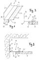
- the wall connection profile 10 shown in FIGS. 1 to 3 has a leg to be attached to a wall, the "wall leg” 12 and a profile part 14 arranged at right angles thereto. Both meet in a profile edge 16.
- the figures show the position of use of the profile on a wall.
- the profile is made from sheet metal (FIG. 3)
- the rib 18 is formed by folds.
- the profile is made of plastic or light metal ( Figure 2), it is solid.
- the wall leg 12 is fastened to a wall 19 with the help of drywall screws.
- the profile part 14 is either screwed to the ceiling (profiles according to Figure 4 or 5) or, in the case of suspended ceilings, arranged lower ( Figures 2 and 3).
- the profile part 14 has a receiving section 21 for screwing on the edges of the cladding panels, boards or plaster supports.
- the free edges of the profile can each have a flange 22 and 23 to stiffen it when made from sheet metal (FIG. 3).
- the edges can have the shape of stiffening ribs 22 'and 23'.
- the flanges or stiffening ribs point away from the wall (22, 22 ') or upwards (23, 23').
- the profile can be painted in the case of sheet metal in the area of the shadow gap and rib 18, in the case of plastic it can be colored as a whole. Painting or coloring can have any, preferably dark color.
- FIG. 2 shows the use of the profile for attaching a suspended ceiling made of plasterboard 25 using a profile made of plastic.
- the left edge of a plasterboard 25 lies in a receiving space 20 below the receiving section 21 and is screwed to the receiving section 21 from below with the help of quick-assembly screws 27.
- the screw heads can be screwed so deep into the plate that openings that are easy to fill remain underneath the heads.
- suspension devices which carry intersecting profiles (the above-mentioned basic and supporting profiles) for holding the parts of the plates which are located further inwards (towards the center of the room). Since the plates are fastened to the wall by the profile 10, the suspension devices closest to the wall need only be arranged at a distance of approximately 1 m to 1.20 m.
- the gypsum plasterboard has a section of reduced thickness on its left edge, which is created by a recess 28 on one side. This recess is swept down so that the entire width of the edge rests against the profile part at the top. The free space formed by the recess 28 is filled.
- the rib 18 ' has a height which is slightly larger than the thickness of the plasterboard to be used in its main area. When filling, there is a clean finish on the lower edge of the rib 18 '.
- FIG. 3 shows the use of the profile 10 for holding boards 30 of a wooden cladding. These boards are tongue and groove, and the quick-assembly screws are screwed into the tongues and covered by the edge below the groove of the next board.
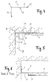
- Figure 4 shows a profile that differs from that shown in Figure 1 only in that the wall leg, here 33, points downward. As a result, this profile can be attached directly to a ceiling.
- a lighting channel can be provided instead of the shadow gap 24.
- the rib 18 or 18 ' has a greater height and the profile part between the profile edge 16 and this rib has a greater width, so that lighting fixtures can be accommodated in the lighting channel and covered by the rib 18 or 18' sufficiently far down.
- the profile as a whole is not colored black but preferably white or beige.
- FIG. 5 shows a profile which differs from the profile according to FIG. 4 in that an additional rib is provided which has a somewhat greater height than the first rib 18 and is referred to here as the “contact section” 35.
- the shadow gap 37 is formed here by the space between the two ribs.
- the distance between the contact section 35 and the wall leg 33 (corresponding approximately to the width of an intermediate section 36 of the profile) is equal to the thickness of a plaster layer 39 to be brought onto the wall.
- the contact section 35 projects further downward as the rib 18.
- the cleaner therefore has the option of placing the upper side of a pull-off bar against the lower piece of the contact section 35 and thus, from a defined starting position, smoothing down the plaster.
- a wallpaper to be glued to the plaster can extend up into the shadow gap 37.
- an upwardly projecting wall arm 12 can be provided instead of the wall arm 33 projecting downwards (as in FIGS. 2 and 3).
- an illumination channel can be provided instead of the shadow gap 37, for which purpose the lengths of the rib 18 and the contact section 35 and the width of the intermediate section 34 must be correspondingly differently dimensioned.
- the profile according to FIG. 5 can be modified such that the wall leg is omitted.
- the profile ends in a horizontal spacing section 36. Otherwise, this profile fulfills the same function as that according to FIG. 5, but it can be produced at a lower cost.
- This profile has no flanges or stiffening ribs on its extreme edges.
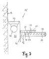
- FIG. 7 shows a wall connection profile through which both a lighting channel 40 and a shadow gap 42 can be formed.
- This profile in turn has a wall leg 12. From its profile part 14 ', however, the section 44 adjacent to the wall runs at a greater height than the receiving section 21.
- a vertical rib 46 is provided, but which has a substantially greater height than the ribs shown above 18 and 18 ′.
- the rib 46 is intended to represent a screen for a lighting fixture 48 which is to be fastened to the profile section 44.
- a strip 50 is fastened to the receiving section 21 with the aid of fast building screws 27.
- Boards 30 for wooden cladding with grooves and tongues are fastened to the strip 50 by the known insertion of right-angled clamps 54 out of the grooves into the strip 50.
- the boards 30 initially protrude more or less far against the rib 46, as shown in dashed lines in FIG. Then the boards with the help of a Circular saw cut in the plane 56, so that there is a shadow gap between the plane 56 and the rib 46. For clean cutting of the board ends, and that at a constant distance from the rib 46, this serves as a contact edge for the circular saw.
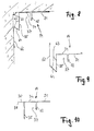
- FIG. 8 shows a profile which is intended to perform the same task as the profile according to FIG. 5 and is also to be attached directly under a ceiling.
- the profile of Figure 8 takes this into account in that the contact section, here 35 ', is not designed as a rib as in Figure 5, but is formed in that two profile sections produced by bending release the corner between the wall and ceiling.
- the profile has a transition section 63, which includes a vertical, flat section, which forms the contact section 35 'and a connecting section 64. This runs from the lower edge of the contact section against the wall and there passes through a further bend in a wall leg 66 .
- the connecting section runs obliquely upwards against the wall.
- the profile has a receiving portion 21, a rib 18 and a space between this rib and the contact portion 35 ', which forms a shadow gap 37.
- the distance between the contact section 35 'and the wall leg 66 is in turn equal to the thickness of a plaster layer to be brought onto the wall, and the contact section protrudes further downwards than the rib 18 so that the cleaner can apply his scraper, as in connection with the third embodiment ( Figure 5) has been described.
- Perforations of sufficient size and number can be provided in the connecting section 64 so that the fresh plaster can be pushed through a little and thus the plaster layer holds firmly on the connecting section.
- Figure 9 shows an embodiment of a profile with the same functions as that of Figure 8, but intended for a suspended ceiling.
- a perpendicularly upwardly extending wall limb 68 attaches to the connecting section 64, which extends obliquely upward against the wall.
- the explanations for the fifth embodiment apply (FIG. 8).
- the intermediate section 34 can also be perforated here, as a result of which the space between the concrete ceiling and the suspended ceiling can be ventilated.
- All profiles shown can be made of light metal, bent from sheet metal or extruded from plastic.
- the wall legs 12, 33, 66 and 68 and the receiving portion 21 of the profiles can be provided with perforations of sufficient number and size so that the profiles can be fastened to the wall and ceiling by mortar alone.
- plaster supports can be screwed on or any other cladding panels.
Landscapes
- Engineering & Computer Science (AREA)
- Architecture (AREA)
- Civil Engineering (AREA)
- Structural Engineering (AREA)
- Physics & Mathematics (AREA)
- Electromagnetism (AREA)
- Finishing Walls (AREA)
- Arrangement Of Elements, Cooling, Sealing, Or The Like Of Lighting Devices (AREA)
Priority Applications (1)
| Application Number | Priority Date | Filing Date | Title |
|---|---|---|---|
| EP19890111724 EP0340810A3 (fr) | 1984-03-10 | 1985-03-02 | Profilé permettant la fixation à des parois |
Applications Claiming Priority (5)
| Application Number | Priority Date | Filing Date | Title |
|---|---|---|---|
| DE3408818 | 1984-03-10 | ||
| DE3408818 | 1984-03-10 | ||
| DE19843417973 DE3417973A1 (de) | 1984-03-10 | 1984-05-15 | Wandanschlussprofil |
| DE3417973 | 1984-05-15 | ||
| EP19890111724 EP0340810A3 (fr) | 1984-03-10 | 1985-03-02 | Profilé permettant la fixation à des parois |
Related Parent Applications (2)
| Application Number | Title | Priority Date | Filing Date |
|---|---|---|---|
| EP85102373.9 Division | 1985-03-02 | ||
| EP85102373A Division EP0154913B1 (fr) | 1984-03-10 | 1985-03-02 | Profilé permettant la fixation à des parois |
Publications (2)
| Publication Number | Publication Date |
|---|---|
| EP0340810A2 true EP0340810A2 (fr) | 1989-11-08 |
| EP0340810A3 EP0340810A3 (fr) | 1992-04-22 |
Family
ID=27191783
Family Applications (1)
| Application Number | Title | Priority Date | Filing Date |
|---|---|---|---|
| EP19890111724 Withdrawn EP0340810A3 (fr) | 1984-03-10 | 1985-03-02 | Profilé permettant la fixation à des parois |
Country Status (1)
| Country | Link |
|---|---|
| EP (1) | EP0340810A3 (fr) |
Cited By (5)
| Publication number | Priority date | Publication date | Assignee | Title |
|---|---|---|---|---|
| EP1132541A3 (fr) * | 2000-03-08 | 2001-11-21 | Stefan Thermann | Profilé de raccordement pour revêtement de plafond |
| EP3026197A1 (fr) * | 2014-11-27 | 2016-06-01 | Roman Zahner | Baguette a profiler |
| AU2018287680B2 (en) * | 2017-06-21 | 2020-04-30 | Dominic Wai Ming Orr | Air-tight cleanroom ceiling: trim device, mounting frame and suspended ceiling system |
| CN114412048A (zh) * | 2022-01-30 | 2022-04-29 | 中建八局装饰工程有限公司 | 一种三面环绕多跌级灯槽装饰结构安装工艺 |
| CN114687507A (zh) * | 2022-03-02 | 2022-07-01 | 黄其红 | 一种古法榫卯式蜂窝吊顶 |
Family Cites Families (4)
| Publication number | Priority date | Publication date | Assignee | Title |
|---|---|---|---|---|
| US1676582A (en) * | 1927-05-05 | 1928-07-10 | Donald R Stuart | Corner piece for buildings |
| DE1708006A1 (de) * | 1966-12-14 | 1971-04-22 | Bergstroem Nils Emil Lennart | Dachgesims |
| DE1904723A1 (de) * | 1969-01-31 | 1970-09-03 | Novopress Gmbh | Einscheiben-Spindelpresse |
| DE8327849U1 (de) * | 1983-09-28 | 1984-01-12 | GERU-PACK GmbH, 3549 Wolfhagen | Sockelprofil fuer waermeschutzsysteme an gebaeudewaenden |
-
1985
- 1985-03-02 EP EP19890111724 patent/EP0340810A3/fr not_active Withdrawn
Cited By (7)
| Publication number | Priority date | Publication date | Assignee | Title |
|---|---|---|---|---|
| EP1132541A3 (fr) * | 2000-03-08 | 2001-11-21 | Stefan Thermann | Profilé de raccordement pour revêtement de plafond |
| EP3026197A1 (fr) * | 2014-11-27 | 2016-06-01 | Roman Zahner | Baguette a profiler |
| AU2018287680B2 (en) * | 2017-06-21 | 2020-04-30 | Dominic Wai Ming Orr | Air-tight cleanroom ceiling: trim device, mounting frame and suspended ceiling system |
| CN114412048A (zh) * | 2022-01-30 | 2022-04-29 | 中建八局装饰工程有限公司 | 一种三面环绕多跌级灯槽装饰结构安装工艺 |
| CN114412048B (zh) * | 2022-01-30 | 2024-01-30 | 中建八局装饰工程有限公司 | 一种三面环绕多跌级灯槽装饰结构安装工艺 |
| CN114687507A (zh) * | 2022-03-02 | 2022-07-01 | 黄其红 | 一种古法榫卯式蜂窝吊顶 |
| CN114687507B (zh) * | 2022-03-02 | 2024-02-06 | 黄其红 | 一种古法榫卯式蜂窝吊顶 |
Also Published As
| Publication number | Publication date |
|---|---|
| EP0340810A3 (fr) | 1992-04-22 |
Similar Documents
| Publication | Publication Date | Title |
|---|---|---|
| DE1658864A1 (de) | Dehnungsfugenabdeckung | |
| DE2355314A1 (de) | Verkleidungsaufbau zum anbringen von tafeln | |
| DE2837429A1 (de) | Vorrichtung und verfahren zum aufbau einer fliesenwand | |
| DE2534160A1 (de) | Schalung zum betonieren | |
| DE2853092A1 (de) | An einer wand mit einem halter befestigbare fussleiste | |
| EP0340810A2 (fr) | Profilé permettant la fixation à des parois | |
| DE3419457A1 (de) | Wandbekleidung | |
| EP3293323A1 (fr) | Système de montage pour plinthe à plancher ou profil de plinthe | |
| DE3202833C2 (de) | Verkleidung für eine in einer Wandöffnung befestigte Zarge einer Haus- oder Zimmertür oder dergleichen | |
| DE29807808U1 (de) | Unterkonstruktion zur Halterung von Fassadenelementen | |
| DE68904505T2 (de) | Unterstuetzung fuer gipskartonplatten und dachdaemmung. | |
| DE4239051A1 (de) | Gebäudewandverkleidung | |
| EP0154913A2 (fr) | Profilé permettant la fixation à des parois | |
| DE2120445A1 (de) | Vorrichtung zum Befestigen von Zwischentrennwänden in Bauwerken | |
| DE19804166C2 (de) | Fassadenbekleidung mit Fassadenplatten | |
| DE3207413C2 (de) | Industriell vorgefertigtes Wandelement | |
| DE3417973A1 (de) | Wandanschlussprofil | |
| DE19625315A1 (de) | Wandsystem | |
| DE19754179C1 (de) | Schiene zum Anschließen einer Platte an eine mit einem Putz zu versehende und zur Platte senkrecht stehende Wand sowie Wandverkleidung für einen Raum mit derartiger Schiene | |
| DE8414798U1 (de) | Wandanschlussprofil | |
| DE1459901B2 (de) | Gebaeude, das eine front mit loggien aufweist | |
| DE2311259A1 (de) | Plattenfoermiger bauteil fuer bedeckung von mauern, geruesten, gelaendern und aehnlichem | |
| DE69932742T2 (de) | Abschlussvorrichtung zur Überbrückung einer Fuge oder einer Ecke zwischen zwei Trockenbauplatten | |
| DE3517727A1 (de) | Putztraegerplatte fuer eine hinterlueftbare aussenwandverkleidung | |
| DE1659779A1 (de) | U-profilaehnliche Leiste aus erhaertbarem Material und deren Verwendung beim ErfassenAbsetzen und Begrenzen von Wandverkleidungsplatten an Bauwerken |
Legal Events
| Date | Code | Title | Description |
|---|---|---|---|
| PUAI | Public reference made under article 153(3) epc to a published international application that has entered the european phase |
Free format text: ORIGINAL CODE: 0009012 |
|
| AC | Divisional application: reference to earlier application |
Ref document number: 154913 Country of ref document: EP |
|
| AK | Designated contracting states |
Kind code of ref document: A2 Designated state(s): AT BE CH DE FR GB IT LI NL SE |
|
| PUAL | Search report despatched |
Free format text: ORIGINAL CODE: 0009013 |
|
| AK | Designated contracting states |
Kind code of ref document: A3 Designated state(s): AT BE CH DE FR GB IT LI NL SE |
|
| STAA | Information on the status of an ep patent application or granted ep patent |
Free format text: STATUS: THE APPLICATION IS DEEMED TO BE WITHDRAWN |
|
| 18D | Application deemed to be withdrawn |
Effective date: 19921023 |