EP0340824B1 - Abzugsvorrichtung für die Stoffbahn an einer Webmaschine - Google Patents
Abzugsvorrichtung für die Stoffbahn an einer Webmaschine Download PDFInfo
- Publication number
- EP0340824B1 EP0340824B1 EP19890200948 EP89200948A EP0340824B1 EP 0340824 B1 EP0340824 B1 EP 0340824B1 EP 19890200948 EP19890200948 EP 19890200948 EP 89200948 A EP89200948 A EP 89200948A EP 0340824 B1 EP0340824 B1 EP 0340824B1
- Authority
- EP
- European Patent Office
- Prior art keywords
- lever
- cloth
- drive roller
- roller
- guide
- Prior art date
- Legal status (The legal status is an assumption and is not a legal conclusion. Google has not performed a legal analysis and makes no representation as to the accuracy of the status listed.)
- Expired
Links
- 239000004744 fabric Substances 0.000 title claims description 61
- 238000009941 weaving Methods 0.000 title claims description 25
- 238000006073 displacement reaction Methods 0.000 claims description 6
- 230000005540 biological transmission Effects 0.000 description 3
- 238000005452 bending Methods 0.000 description 2
- 238000010276 construction Methods 0.000 description 2
- 238000010586 diagram Methods 0.000 description 2
- 230000000694 effects Effects 0.000 description 2
- 238000000034 method Methods 0.000 description 2
- 238000010009 beating Methods 0.000 description 1
- 230000001105 regulatory effect Effects 0.000 description 1
- 230000033764 rhythmic process Effects 0.000 description 1
Images




Classifications
-
- D—TEXTILES; PAPER
- D03—WEAVING
- D03D—WOVEN FABRICS; METHODS OF WEAVING; LOOMS
- D03D49/00—Details or constructional features not specially adapted for looms of a particular type
- D03D49/04—Control of the tension in warp or cloth
- D03D49/20—Take-up motions; Cloth beams
Definitions
- This invention concerns a device for taking up the cloth on weaving machines, more particularly a cloth take-up device for taking up the cloth under tension.
- Conventional devices for taking up the cloth under tension from the fell line consist of a drive roller mounted at a fixed place, past which the cloth is led, and a pressure roller which by means of springs operates on the drive roller and the cloth. In such devices, the pressure between the pressure roller and the drive roller can never be greater than the spring pressure.
- the present invention has as its aim a device by means of which the pressure between the pressure rollers and the drive roller can be in any desired relation to the force in the cloth.
- the pressure can even be significantly greater than on known devices, without requiring a construction that takes lots of space.
- the device has a mechanism by means of which it is possible to adjust the relation between, on the one hand, the pressure between the drive roller and the support rollers, and on the other hand the cloth tension, either manually or automatically, as a function of the weaving parameters and/or measured values.
- the invention also has as its aim a device which optimally prevents the cloth from slipping, such that the evenness of the cloth is assured, both in the normal weaving process and in circumstances in which the warp threads are relaxed and/or in which the tension at the cloth roll end disappears.
- the device also enables a large tension force to be exerted on smooth cloths, without the risk of damaging the cloths.
- the device according to the invention also enables great stiffness in bend of the whole structure to be obtained while taking a minimum amount of space in the machine, so that the pressure exerted on the cloth is the same over the whole weaving width, so avoiding creases or deformations.
- the invention relates to device for taking up the cloth on weaving machines, comprising a drive roller for the cloth and a pressure roller which co-operates with the drive roller, the pressure roller being pivotably mounted on the frame of the weaving machine, characterized in that said pressure roller is mounted at one end of a lever; that the lever at its end opposite to the end carrying the pressure roller is provided with a guide mounted to said lever; that the guide is located such that during use of the weaving machine the cloth is bent over the guide and is led to the drive roller; and that the pressure roller exerts a force on the drive roller due to the tension force in the cloth acting on the guide.
- the drive roller preferably rests freely between two support rollers on the one hand and the above mentioned pressure roller on the other hand.
- Fig. 1 shows a weaving machine which uses a device 1 according to the invention for taking up the cloth 2 under tension.
- the device 1 has as its aim to keep the cloth 2 taut between said device and the fell line 3 and to keep taut the warp threads and to take up the cloth efficiently towards the cloth beam 5.
- the shed 6, the heddles 7, the sley 8 and the warp beam 9 are also shown schematically.
- the device 1 essentially consists of a drive roller 10 round which the cloth 2 is led, and a lever 12 mounted on the frame 11 of the weaving machine, on one end of which is a pressure roller 13 which operates on the drive roller 10, and on the other end of which is a guide 14 past which the cloth 2 is led to the drive roller 10.
- the drive roller 10 is driven by means of a drive 15, which together with the drive 16 of the sley 8 and the drive 17 of the cloth beam 5 is controlled by the control unit 18 of the weaving machine.
- the drive 15 consists of a drive motor 19 and a toothed belt 20, such that there is perfect synchronization between the drive roller 10 and the motor 19.
- the drive 17 preferably comprises a controlled motor 21 and a transmission 21 consisting of an ordinary belt 22, such that slippage can occur between the cloth beam 5 and the motor 21 if a certain torque is exceeded.
- the drive roller 10 lies freely, without any other pivot mounting, between at least two support rollers 23 and 24 on the one hand and the above-mentioned pressure roller 13 on the other.
- the latter has a dressing 25 in rubber or suchlike.
- the cloth 2 is preferably led directly from the above-mentioned guide 14 onto the drive roller 10, i.e. without the cloth being bent round the pressure roller 13. Down-cloth of the drive roller 10 there is a guide 26, situated free of the drive roller 10, so that the cloth 2 is led directly from the drive roller 10 to said guide 26.
- the guide 14 has as much frictional resistance as possible, and consists preferably of a spreader bar. As will be seen from the description of the operation below, it is necessary for the guide 14 to offer optimum resistance to the cloth.
- the angle of contact between the cloth 2 and the guide 14 should preferably be at least 90 degrees.
- pressure springs 27 also act on the end of the lever 12 on which the pressure roller 13 is mounted. During the normal weaving process, the pressure springs 27 provide a supplementary pressure to the pressure already supplied by the lever 12.
- FIG. 3 A more detailed embodiment is shown in figs. 3 and 4.
- the special feature here is that the support roller 24 is mounted on a pivoting part 28 which swivels on an axis 29 attached solidly to the frame 11.
- the pivoting part 28 of course has a suitable locking mechanism 30, for example a tensioned component which can operate on the fixed axis 29, in order to hold the pivoting part 28 in the raised position during normal operation of the weaving machine.
- the fixed support 31 ensures that the drive roller 10 is supported when the pivoting part 28 is swivelled away.
- the pressure roller 13 together with the guide 14, the support rollers 23 and 24 and the guide 26 are supported over the whole weaving width by sections, 32 to 35 respectively, in order to prevent bending and uneven distribution of forces.
- the pressure roller 13 and the supporting roller 24 are held in their seats in the sections 32 and 34 by means of detachable support sections 36, such that they also remain supported when the drive roller 10 is removed.
- An adjusting screw 37 which serves as a stop for the section 32 can be provided, such that during replacement of the drive roller 10 the pivoting part 28 can be locked in the most suitable position.
- the pressure roller 13 and possibly also the support rollers 23 and 24 may or may not be driven.
- fig. 5 shows the guide 14 in the form of a spreader bar.
- the ends have screw-shaped projections 41 which keep the cloth 2 spread out.
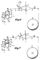
- Figs. 6 and 7 illustrate how the forces in the cloth 2 operate on the lever 12.
- the sley 8 is beating up to the fell line 3.
- the fell line 3 is displaced forwards over a distance D.
- the cloth 2 between the fell line 3 and the drive roller 10 relaxes as a result and slides more easily over the frictional guide 14 and is carried along by the drive roller 10.
- Fb there is a high tension
- Fig. 8 shows the equilibrium of forces for the embodiment according to fig. 3. From this figure it can be seen that if a maximum pressure Fd is required, the distance A must be chosen as great as possible and the distances B and C as small as possible. Clearly, when choosing the distances A, B and C, a compromise must be made between, on the one hand, the desired effect regarding the amount of pressure between the pressure roller 13 and the drive roller 10, and on the other the construction possibilities.
- Fig. 9 shows a variant of the device. Since in this case the support roller 24 is situated above, and the support roller 23 and the pressure roller 13 underneath, the above-mentioned support 31 is not necessary.
- the embodiment shown in fig. 9 is more intended for heavy cloths.
- the tension Fa falls to practically zero, and the pressure roller 13 is only held against the drive roller 10 by the pressure springs 27.
- the tension in such a heavy cloth is normally very high, so it is not necessary for the lever 12 to supply a multiplication of force any more.
- the pivot 42 can also be located nearer to the guide 14 than the pressure roller 13.
- the guide 14, the drive roller 10 and the support roller 24 are preferably arranged so that the plane 43 traversed by the long axes of the support roller 24 and the drive roller 10 is parallel to the plane 44 of the cloth 2 between the guide 14 and the drive roller 10. In this way optimum pressure is achieved between the pressure roller 24 and the drive roller 10.
- Fig. 10 shows a particular embodiment in which the device has a mechanism 45 by means of which the lever 12 can be moved radially with respect to its axis of rotation.
- the mechanism 45 consists of a shaft 47 driven by a motor 46, with on the shaft 47 an excentric pin 48 which is mounted fixed to this shaft 47, on which the lever 12 is swivel-mounted by means of a bearing 49.
- the motor 46 and the shaft 47 are coupled to each other by means of a worm 50 and wormwheel 51.
- the lever 12 can be moved in the X and Y directions.
- the guide 14 can be made to carry out a displacement V such that the cloth 2 is tensioned to a greater or less extent.
- a displacement V such that the cloth 2 is tensioned to a greater or less extent.
- the motor 46 is preferably coupled to a control unit 52 which in turn receives signals from a number of detectors, such as a detector 53 in order to measure the position of the fell line 3 and a detector 54 to measure the tension in the cloth, so that the displacement of the excentric pin 48 can be automatically regulated in order to avoid starting marks.
- the control unit 18 can also make adjustments according to certain weaving parameters such as the start/stop signals and the type of cloth.
- the motor 46 can also turn with a particular rhythm, in order to obtain special effects in the cloth.
- Figs. 12 and 13 show yet another embodiment in which the above-mentioned lever 12 has a mechanism 55 which not only enables the guide 14 to be moved, but also enables the transmission ratio of the lever 12 to be altered at the same time.
- the mechanism 55 consists of a shaft 47 attached to the weaving machine frame, with on it an excentric pin 48 which is movable round the shaft, around which pin 48 the lever 12 can pivot by means of a bearing 49, and a motor 56 which in this case does not drive the shaft 47 but rather the excentric pin 48, such that any desired angular displacement can be set between the pin 48 and the lever 12.
- the motor 56 can for instance be mounted on the lever 12, while pin 48 is driven by means of a wormwheel 57 and a worm 58.
- Fig. 14 shows the lever according to fig. 12 for a different position of the excentric pin 48.
- the mechanical advantage of the lever with respect to its pivot 42 is different for the positions shown in figs. 12 and 14 respectively.
- the transmission ratio can be set to a maximum.
- the mechanism for rotating the pin 48 with respect to the lever 12 can of course be of any desired type. Setting can also be done manually.
Landscapes
- Engineering & Computer Science (AREA)
- Textile Engineering (AREA)
- Looms (AREA)
Claims (17)
Applications Claiming Priority (2)
| Application Number | Priority Date | Filing Date | Title |
|---|---|---|---|
| BE8800495 | 1988-05-03 | ||
| BE8800495A BE1001913A3 (nl) | 1988-05-03 | 1988-05-03 | Inrichting voor het afvoeren van het weefsel bij weefmachines. |
Publications (2)
| Publication Number | Publication Date |
|---|---|
| EP0340824A1 EP0340824A1 (de) | 1989-11-08 |
| EP0340824B1 true EP0340824B1 (de) | 1992-08-12 |
Family
ID=3883391
Family Applications (1)
| Application Number | Title | Priority Date | Filing Date |
|---|---|---|---|
| EP19890200948 Expired EP0340824B1 (de) | 1988-05-03 | 1989-04-14 | Abzugsvorrichtung für die Stoffbahn an einer Webmaschine |
Country Status (3)
| Country | Link |
|---|---|
| EP (1) | EP0340824B1 (de) |
| BE (1) | BE1001913A3 (de) |
| DE (1) | DE68902418T2 (de) |
Families Citing this family (3)
| Publication number | Priority date | Publication date | Assignee | Title |
|---|---|---|---|---|
| JP4089823B2 (ja) * | 2003-06-19 | 2008-05-28 | 津田駒工業株式会社 | 織機のプレスロール装置 |
| CN113249856B (zh) * | 2021-07-08 | 2021-09-10 | 南通云翔机械制造有限责任公司 | 一种具有亲肤面料的有机织物织造设备 |
| CN115948845B (zh) * | 2023-02-08 | 2023-12-08 | 深圳市华利佳达实业有限公司 | 一种织带机的织带导向施压收卷机构 |
Family Cites Families (4)
| Publication number | Priority date | Publication date | Assignee | Title |
|---|---|---|---|---|
| NL6905194A (de) * | 1969-04-02 | 1970-10-06 | ||
| CH632543A5 (de) * | 1978-12-05 | 1982-10-15 | Sulzer Ag | Abzugsvorrichtung fuer die stoffbahn an einer textilmaschine. |
| DE3664648D1 (en) * | 1985-12-06 | 1989-08-31 | Sulzer Ag | Draw-off device for the cloth in a textile machine |
| BE904266A (nl) * | 1986-02-24 | 1986-08-25 | Picanol Nv | Doekopwikkelinrichting voor weefmachines. |
-
1988
- 1988-05-03 BE BE8800495A patent/BE1001913A3/nl not_active IP Right Cessation
-
1989
- 1989-04-14 DE DE1989602418 patent/DE68902418T2/de not_active Expired - Lifetime
- 1989-04-14 EP EP19890200948 patent/EP0340824B1/de not_active Expired
Also Published As
| Publication number | Publication date |
|---|---|
| BE1001913A3 (nl) | 1990-04-10 |
| DE68902418D1 (de) | 1992-09-17 |
| DE68902418T2 (de) | 1992-12-03 |
| EP0340824A1 (de) | 1989-11-08 |
Similar Documents
| Publication | Publication Date | Title |
|---|---|---|
| JP5085661B2 (ja) | 機械織機のバックレスト | |
| EP0421665B1 (de) | Vorrichtung zum Abziehen von Strickwaren | |
| US3308854A (en) | Loom for weaving | |
| EP0340824A1 (de) | Abzugsvorrichtung für die Stoffbahn an einer Webmaschine | |
| US4098136A (en) | Tension roller in the drive mechanism between a weaving machine and a dobby | |
| GB2028386A (en) | Weaving loom | |
| US4125131A (en) | Fixed driving connection between a guide roller and delivery roller of a loom | |
| US4403630A (en) | Apparatus for tensioning the warp thread sheet of a loom | |
| EP0129386A2 (de) | Webmaschine | |
| US5099890A (en) | Warp tensioning apparatus for producing a seersucker fabric | |
| US3900051A (en) | Apparatus and method for supplying pile warp threads in a loom for weaving terry cloth | |
| KR102133635B1 (ko) | 좌석용 위치 조절장치 | |
| US4224967A (en) | Warp tension control mechanism for loom | |
| US4781222A (en) | Fabric winding device for weaving looms | |
| US4274449A (en) | Band guide for shuttleless looms | |
| US3707996A (en) | Take-up device having a tension-derived compacting means | |
| US3860044A (en) | Warp tension control mechanism | |
| JP4249036B2 (ja) | 織機の送出装置 | |
| CS202050B2 (en) | Weft takeoff and length metering apparatus for weaving looms with programmed weft selector | |
| US6098670A (en) | Apparatus for tensioning warp threads for a weaving machine and a weaving machine with an apparatus of this kind | |
| EP1065305A2 (de) | Spannvorrichtung für den Grundkettfadenablauf in Frottierwebmaschinen mit bewegbarem Tuch | |
| US4058143A (en) | Constant tension regulator of positively unwound flexible material, particularly warp threads in weaving machines | |
| US4722369A (en) | Take-up device for the cloth beam of a textile machine | |
| US3903930A (en) | Weft selector for shuttleless weaving machine | |
| CN219079754U (zh) | 一种可调节式整经机 |
Legal Events
| Date | Code | Title | Description |
|---|---|---|---|
| PUAI | Public reference made under article 153(3) epc to a published international application that has entered the european phase |
Free format text: ORIGINAL CODE: 0009012 |
|
| AK | Designated contracting states |
Kind code of ref document: A1 Designated state(s): CH DE FR IT LI |
|
| 17P | Request for examination filed |
Effective date: 19891206 |
|
| 17Q | First examination report despatched |
Effective date: 19910612 |
|
| GRAA | (expected) grant |
Free format text: ORIGINAL CODE: 0009210 |
|
| AK | Designated contracting states |
Kind code of ref document: B1 Designated state(s): CH DE FR IT LI |
|
| ITF | It: translation for a ep patent filed | ||
| REF | Corresponds to: |
Ref document number: 68902418 Country of ref document: DE Date of ref document: 19920917 |
|
| ET | Fr: translation filed | ||
| PLBE | No opposition filed within time limit |
Free format text: ORIGINAL CODE: 0009261 |
|
| STAA | Information on the status of an ep patent application or granted ep patent |
Free format text: STATUS: NO OPPOSITION FILED WITHIN TIME LIMIT |
|
| 26N | No opposition filed | ||
| PGFP | Annual fee paid to national office [announced via postgrant information from national office to epo] |
Ref country code: FR Payment date: 19970321 Year of fee payment: 9 |
|
| PGFP | Annual fee paid to national office [announced via postgrant information from national office to epo] |
Ref country code: DE Payment date: 19970407 Year of fee payment: 9 |
|
| PGFP | Annual fee paid to national office [announced via postgrant information from national office to epo] |
Ref country code: CH Payment date: 19970414 Year of fee payment: 9 |
|
| PG25 | Lapsed in a contracting state [announced via postgrant information from national office to epo] |
Ref country code: LI Free format text: LAPSE BECAUSE OF NON-PAYMENT OF DUE FEES Effective date: 19980430 Ref country code: FR Free format text: THE PATENT HAS BEEN ANNULLED BY A DECISION OF A NATIONAL AUTHORITY Effective date: 19980430 Ref country code: CH Free format text: LAPSE BECAUSE OF NON-PAYMENT OF DUE FEES Effective date: 19980430 |
|
| REG | Reference to a national code |
Ref country code: CH Ref legal event code: PL |
|
| PG25 | Lapsed in a contracting state [announced via postgrant information from national office to epo] |
Ref country code: DE Free format text: LAPSE BECAUSE OF NON-PAYMENT OF DUE FEES Effective date: 19990202 |
|
| REG | Reference to a national code |
Ref country code: FR Ref legal event code: ST |
|
| PG25 | Lapsed in a contracting state [announced via postgrant information from national office to epo] |
Ref country code: IT Free format text: LAPSE BECAUSE OF NON-PAYMENT OF DUE FEES;WARNING: LAPSES OF ITALIAN PATENTS WITH EFFECTIVE DATE BEFORE 2007 MAY HAVE OCCURRED AT ANY TIME BEFORE 2007. THE CORRECT EFFECTIVE DATE MAY BE DIFFERENT FROM THE ONE RECORDED. Effective date: 20050414 |