EP0340834A2 - System von Ventilen und Ventilgetriebe für Brennkraftmaschinen mit hoher spezifischer Leistung - Google Patents
System von Ventilen und Ventilgetriebe für Brennkraftmaschinen mit hoher spezifischer Leistung Download PDFInfo
- Publication number
- EP0340834A2 EP0340834A2 EP89201024A EP89201024A EP0340834A2 EP 0340834 A2 EP0340834 A2 EP 0340834A2 EP 89201024 A EP89201024 A EP 89201024A EP 89201024 A EP89201024 A EP 89201024A EP 0340834 A2 EP0340834 A2 EP 0340834A2
- Authority
- EP
- European Patent Office
- Prior art keywords
- valves
- respect
- axis
- stems
- camshaft
- Prior art date
- Legal status (The legal status is an assumption and is not a legal conclusion. Google has not performed a legal analysis and makes no representation as to the accuracy of the status listed.)
- Withdrawn
Links
Images

Classifications
-
- F—MECHANICAL ENGINEERING; LIGHTING; HEATING; WEAPONS; BLASTING
- F02—COMBUSTION ENGINES; HOT-GAS OR COMBUSTION-PRODUCT ENGINE PLANTS
- F02F—CYLINDERS, PISTONS OR CASINGS, FOR COMBUSTION ENGINES; ARRANGEMENTS OF SEALINGS IN COMBUSTION ENGINES
- F02F1/00—Cylinders; Cylinder heads
- F02F1/24—Cylinder heads
- F02F1/42—Shape or arrangement of intake or exhaust channels in cylinder heads
- F02F1/4214—Shape or arrangement of intake or exhaust channels in cylinder heads specially adapted for four or more valves per cylinder
- F02F1/4221—Shape or arrangement of intake or exhaust channels in cylinder heads specially adapted for four or more valves per cylinder particularly for three or more inlet valves
-
- F—MECHANICAL ENGINEERING; LIGHTING; HEATING; WEAPONS; BLASTING
- F01—MACHINES OR ENGINES IN GENERAL; ENGINE PLANTS IN GENERAL; STEAM ENGINES
- F01L—CYCLICALLY OPERATING VALVES FOR MACHINES OR ENGINES
- F01L1/00—Valve-gear or valve arrangements, e.g. lift-valve gear
- F01L1/26—Valve-gear or valve arrangements, e.g. lift-valve gear characterised by the provision of two or more valves operated simultaneously by same transmitting-gear; peculiar to machines or engines with more than two lift-valves per cylinder
- F01L1/265—Valve-gear or valve arrangements, e.g. lift-valve gear characterised by the provision of two or more valves operated simultaneously by same transmitting-gear; peculiar to machines or engines with more than two lift-valves per cylinder peculiar to machines or engines with three or more intake valves per cylinder
-
- F—MECHANICAL ENGINEERING; LIGHTING; HEATING; WEAPONS; BLASTING
- F02—COMBUSTION ENGINES; HOT-GAS OR COMBUSTION-PRODUCT ENGINE PLANTS
- F02B—INTERNAL-COMBUSTION PISTON ENGINES; COMBUSTION ENGINES IN GENERAL
- F02B2275/00—Other engines, components or details, not provided for in other groups of this subclass
- F02B2275/18—DOHC [Double overhead camshaft]
-
- F—MECHANICAL ENGINEERING; LIGHTING; HEATING; WEAPONS; BLASTING
- F02—COMBUSTION ENGINES; HOT-GAS OR COMBUSTION-PRODUCT ENGINE PLANTS
- F02F—CYLINDERS, PISTONS OR CASINGS, FOR COMBUSTION ENGINES; ARRANGEMENTS OF SEALINGS IN COMBUSTION ENGINES
- F02F1/00—Cylinders; Cylinder heads
- F02F1/24—Cylinder heads
- F02F2001/244—Arrangement of valve stems in cylinder heads
- F02F2001/245—Arrangement of valve stems in cylinder heads the valve stems being orientated at an angle with the cylinder axis
Definitions
- the present invention relates to a system of valves and related operating devices for internal combustion engines having high specific horsepower.
- the three intake valves would have to be arranged with at least one of them having the stem not parallel to those of the other two so that the extremities of all the stems may be brought onto the same axis and thus permit their operation by a single camshaft, as it is not possible, for reasons of space and also of the design of the combustion chamber, to arrange the three valves in line.
- An internal combustion engine having three intake valves with inclined stems converging onto a single camshaft is described, for example, in European patent No. 0063385.
- object of the present invention has been that of accomplishing a system of valves and related operating devices for internal combustion engines having high specific horsepower, to permit the use of a single camshaft for the operation of homologous valves, limiting the construction difficulties of the combustion chamber and at the same time avoiding the necessity of additional organs such as the finger rocker arm mentioned above.
- a system of valves and related operating devices comprising for each cylinder a group of intake valves and a group of exhaust valves, wherein at least one of said groups is formed by three circumferentially spaced out valves operated by a single camshaft, characterized in that said three valves consist of a central valve and of two lateral valves having a smaller diameter with respect to the central one.
- said lateral valves are provided with stems parallel to one another and inclined with respect to that of the central valve and at least one of the stems of said lateral and central valves has its own axis displaced laterally with respect to the axis of rotation of said camshaft, there being provided means for offsetting the lateral displacement of said axis.
- the above means may be constituted, for example, by a guide cup placed on the summit of the stem having a displaced axis and in its turn displaced laterally with respect to it in the opposite direction and in an amount equal to the lateral displacement of said stem.
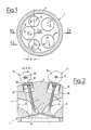
- a head of a cylinder 1 of an internal combustion engine which by way of an example is provided with three intake valves 2, 2′ and with two exhaust valves 3.
- the five valves are arranged on the head 4 of the cylinder in a circumferentially spaced out position which is also approximately symmetrical with respect to the cylinder's central axis.
- the lateral valves 2 of the three intake valves 2, 2′ have heads 5 having a reduced diameter with respect to the head 5′ of the central valve 2′ and define with the latter a lower distance between centres equal to D.
- the lateral intake valves 2 operate in respective intake ports 7 and have stems 6 having axes parallel to one another and inclined with respect to the axis of the stem 6′ of the central intake valve 2′ (operating in an intake port 7′), thus defining an upper distance between centres d less than the lower one D.
- the exhaust valves 3 in turn operate in exhaust ports 8 and have stems 13 having axes parallel to one another.
- the operation of the intake valves 2 and 2′ is provided by a first camshaft 9 having axis of rotation 10, while the operation of the exhaust valves 3 is provided by a second camshaft 11 having axis of rotation 12.
- the stems 13 of the exhaust valves 3 have axes which pass through the axis of rotation 12 of the camshaft 11 and are operated by the latter's cams 14 by means of guide cups 15 slidably housed in respective seats 16 of the head 4.
- the stems 6, 6′ of the intake valves 2, 2′ are on the other hand displaced laterally in opposite directions with respect to the axis of rotation 10 of the camshaft 9, which operates them with cams 17, 17′ by means of guide cups 18, 18′ slidably housed in respective seats 19, 19′ of the head 4.
- the cups 18 of the lateral valves 2 are displaced laterally with respect to the axes of the stems 6, in a direction and in an amount such as to offset the lateral displacement of the above axes with respect to the axis of rotation of the camshaft 9.
- a similar displacement takes place, in the opposite direction, in the case of the cup 18′ of the central valve 2′ (Fig. 3).
- the reciprocal inclination of the stems of the intake valves 2, 2′ is thus contained within acceptable limits while still maintaining the possibility of using a single camshaft 9 and without having to recourse to auxiliary components such as rocker arms or such.
- the cups 18, 18′ could be aligned along the same axis as the stems 6, 6′ and the offset of the lateral displacements of the axes of the stems 6, 6′ could be obtained by having cups of an appropriately larger size. This solution is shown in Fig.s 4 and 5.
- the axes of the stems 6 could pass through the axis of rotation 10 of the camshaft 9 and only the axis of the stem 6′ be laterally displaced with respect to the above axis of rotation, and vice versa.
Landscapes
- Engineering & Computer Science (AREA)
- Mechanical Engineering (AREA)
- General Engineering & Computer Science (AREA)
- Chemical & Material Sciences (AREA)
- Combustion & Propulsion (AREA)
- Valve-Gear Or Valve Arrangements (AREA)
Applications Claiming Priority (2)
| Application Number | Priority Date | Filing Date | Title |
|---|---|---|---|
| IT2046788 | 1988-05-05 | ||
| IT20467/88A IT1217503B (it) | 1988-05-05 | 1988-05-05 | Sistema di valvola e relativi comandi di azionamento per motore a combustione interna ad elevata potenza specifica |
Publications (2)
| Publication Number | Publication Date |
|---|---|
| EP0340834A2 true EP0340834A2 (de) | 1989-11-08 |
| EP0340834A3 EP0340834A3 (de) | 1990-01-31 |
Family
ID=11167387
Family Applications (1)
| Application Number | Title | Priority Date | Filing Date |
|---|---|---|---|
| EP89201024A Withdrawn EP0340834A3 (de) | 1988-05-05 | 1989-04-20 | System von Ventilen und Ventilgetriebe für Brennkraftmaschinen mit hoher spezifischer Leistung |
Country Status (3)
| Country | Link |
|---|---|
| EP (1) | EP0340834A3 (de) |
| JP (1) | JPH01313607A (de) |
| IT (1) | IT1217503B (de) |
Cited By (8)
| Publication number | Priority date | Publication date | Assignee | Title |
|---|---|---|---|---|
| FR2656898A1 (fr) * | 1990-01-11 | 1991-07-12 | Peugeot | Agencement de soupapes dans un moteur a combustion. |
| EP0444562A1 (de) * | 1990-03-02 | 1991-09-04 | FERRARI S.p.A. | Steuerung, insbesondere für eine Brennkraftmaschine mit einer Anzahl von Ventilen je Zylinder |
| EP0462568A1 (de) * | 1990-06-19 | 1991-12-27 | FERRARI S.p.A. | Steuervorrichtung, insbesondere für eine Brennkraftmaschine mit einer Anzahl von Ventilen je Zylinder |
| US5094197A (en) * | 1991-03-01 | 1992-03-10 | Ferrari S.P.A. | Timing system, particularly for an internal combustion engine with a number of valves per cyclinder |
| EP0595316A1 (de) * | 1992-10-28 | 1994-05-04 | Yamaha Hatsudoki Kabushiki Kaisha | Zylinderkopf und Ventilanordnung einer Mehrventil-Brennkraftmaschine |
| EP0615058A1 (de) * | 1993-03-09 | 1994-09-14 | Dr.Ing. h.c. F. PORSCHE AKTIENGESELLSCHAFT | Zylinderkopf für eine Brennkraftmaschine |
| EP0692613A1 (de) * | 1994-06-17 | 1996-01-17 | Yamaha Hatsudoki Kabushiki Kaisha | Brennkraftmaschine und Verfahren zum Zuführen von Luft zum Brennraum einer Brennkraftmaschine |
| DE19730842A1 (de) * | 1997-07-18 | 1999-01-21 | Audi Ag | Brennkraftmaschine |
Family Cites Families (2)
| Publication number | Priority date | Publication date | Assignee | Title |
|---|---|---|---|---|
| JPH07103818B2 (ja) * | 1983-11-29 | 1995-11-08 | ヤマハ発動機株式会社 | 4サイクルエンジンのピストン |
| DE3669559D1 (de) * | 1986-10-02 | 1990-04-19 | Audi Ag | Viertakt-brennkraftmaschine. |
-
1988
- 1988-05-05 IT IT20467/88A patent/IT1217503B/it active
-
1989
- 1989-04-20 EP EP89201024A patent/EP0340834A3/de not_active Withdrawn
- 1989-05-01 JP JP1109270A patent/JPH01313607A/ja active Pending
Cited By (10)
| Publication number | Priority date | Publication date | Assignee | Title |
|---|---|---|---|---|
| FR2656898A1 (fr) * | 1990-01-11 | 1991-07-12 | Peugeot | Agencement de soupapes dans un moteur a combustion. |
| EP0444562A1 (de) * | 1990-03-02 | 1991-09-04 | FERRARI S.p.A. | Steuerung, insbesondere für eine Brennkraftmaschine mit einer Anzahl von Ventilen je Zylinder |
| EP0462568A1 (de) * | 1990-06-19 | 1991-12-27 | FERRARI S.p.A. | Steuervorrichtung, insbesondere für eine Brennkraftmaschine mit einer Anzahl von Ventilen je Zylinder |
| US5094197A (en) * | 1991-03-01 | 1992-03-10 | Ferrari S.P.A. | Timing system, particularly for an internal combustion engine with a number of valves per cyclinder |
| EP0595316A1 (de) * | 1992-10-28 | 1994-05-04 | Yamaha Hatsudoki Kabushiki Kaisha | Zylinderkopf und Ventilanordnung einer Mehrventil-Brennkraftmaschine |
| EP0615058A1 (de) * | 1993-03-09 | 1994-09-14 | Dr.Ing. h.c. F. PORSCHE AKTIENGESELLSCHAFT | Zylinderkopf für eine Brennkraftmaschine |
| US5408958A (en) * | 1993-03-09 | 1995-04-25 | Dr. Ing. H.C.F. Porsche Ag | Cylinder head for an internal-combustion engine |
| EP0692613A1 (de) * | 1994-06-17 | 1996-01-17 | Yamaha Hatsudoki Kabushiki Kaisha | Brennkraftmaschine und Verfahren zum Zuführen von Luft zum Brennraum einer Brennkraftmaschine |
| US5606942A (en) * | 1994-06-17 | 1997-03-04 | Yamaha Hatsudoki Kabushiki Kaisha | Valve operating system for multi-valve engine |
| DE19730842A1 (de) * | 1997-07-18 | 1999-01-21 | Audi Ag | Brennkraftmaschine |
Also Published As
| Publication number | Publication date |
|---|---|
| IT8820467A0 (it) | 1988-05-05 |
| EP0340834A3 (de) | 1990-01-31 |
| IT1217503B (it) | 1990-03-22 |
| JPH01313607A (ja) | 1989-12-19 |
Similar Documents
| Publication | Publication Date | Title |
|---|---|---|
| US4932377A (en) | Multivalve cylinder engine | |
| GB2147661A (en) | Double overhead cam cylinder head | |
| EP0483109B1 (de) | Nockenwellenanordnung für eine Mehrventil-Brennkraftmaschine | |
| JPS60216013A (ja) | 内燃機関の吸気弁構造 | |
| JPH05195736A (ja) | エンジンのバルブ駆動装置 | |
| EP0340834A2 (de) | System von Ventilen und Ventilgetriebe für Brennkraftmaschinen mit hoher spezifischer Leistung | |
| JP2599317B2 (ja) | シリンダに多数のバルブを具備した特に内燃機関用タイミング機構 | |
| US4638774A (en) | Valve actuating mechanism for internal combustion engine | |
| US5131355A (en) | Balancing arrangement in 8-cylinder, 4-stroke engines | |
| US4784091A (en) | Cylinder head cover structure for a V-type engine | |
| EP0322572B1 (de) | Ventilsteuervorrichtung für Mehrventil-Brennkraftmaschine | |
| EP0428691A1 (de) | Zylinderköpfe für brennkraftmaschinen. | |
| US6098581A (en) | Variable valve control for piston internal combustion engine | |
| JPS58113512A (ja) | 4サイクルエンジン | |
| EP0313140A1 (de) | Steuerzeitvorrichtung für Brennkraftmaschine mit hoher spezifischer Leistung | |
| JPH03121207A (ja) | 弁で制御される内燃機関 | |
| US3418984A (en) | Internal combustion engine | |
| US5184580A (en) | Timing system for an internal combustion engine | |
| JP2607763B2 (ja) | シリンダに多数のバルブを具備した特に内燃機関用タイミング機構 | |
| EP0241434A2 (de) | Ventilkontrollvorrichtung für die Steuerung einer Brennkraftmaschine | |
| JP2738866B2 (ja) | Dohcエンジンの動弁装置 | |
| JP2683388B2 (ja) | 4サイクルエンジンの吸気装置 | |
| JP2545506B2 (ja) | 四サイクルエンジンの動弁装置 | |
| JPH02119605A (ja) | 4サイクルエンジンの動弁装置 | |
| JPH0337309A (ja) | Dohcエンジンの動弁装置 |
Legal Events
| Date | Code | Title | Description |
|---|---|---|---|
| PUAI | Public reference made under article 153(3) epc to a published international application that has entered the european phase |
Free format text: ORIGINAL CODE: 0009012 |
|
| AK | Designated contracting states |
Kind code of ref document: A2 Designated state(s): DE ES FR GB SE |
|
| PUAL | Search report despatched |
Free format text: ORIGINAL CODE: 0009013 |
|
| AK | Designated contracting states |
Kind code of ref document: A3 Designated state(s): DE ES FR GB SE |
|
| STAA | Information on the status of an ep patent application or granted ep patent |
Free format text: STATUS: THE APPLICATION IS DEEMED TO BE WITHDRAWN |
|
| 18D | Application deemed to be withdrawn |
Effective date: 19900801 |