EP0340913B1 - Appareil électrique avec deux générateurs - Google Patents
Appareil électrique avec deux générateurs Download PDFInfo
- Publication number
- EP0340913B1 EP0340913B1 EP89303398A EP89303398A EP0340913B1 EP 0340913 B1 EP0340913 B1 EP 0340913B1 EP 89303398 A EP89303398 A EP 89303398A EP 89303398 A EP89303398 A EP 89303398A EP 0340913 B1 EP0340913 B1 EP 0340913B1
- Authority
- EP
- European Patent Office
- Prior art keywords
- generator
- output
- current
- generators
- voltage
- Prior art date
- Legal status (The legal status is an assumption and is not a legal conclusion. Google has not performed a legal analysis and makes no representation as to the accuracy of the status listed.)
- Expired - Lifetime
Links
Images

Classifications
-
- H—ELECTRICITY
- H02—GENERATION; CONVERSION OR DISTRIBUTION OF ELECTRIC POWER
- H02J—ELECTRIC POWER NETWORKS; CIRCUIT ARRANGEMENTS OR SYSTEMS FOR SUPPLYING OR DISTRIBUTING ELECTRIC POWER; SYSTEMS FOR STORING ELECTRIC ENERGY
- H02J7/00—Circuit arrangements for charging or discharging batteries or for supplying loads from batteries
- H02J7/14—Circuit arrangements for charging or discharging batteries or for supplying loads from batteries for charging batteries from dynamo-electric generators driven at varying speed, e.g. on vehicle
- H02J7/1423—Circuit arrangements for charging or discharging batteries or for supplying loads from batteries for charging batteries from dynamo-electric generators driven at varying speed, e.g. on vehicle with multiple batteries
-
- H—ELECTRICITY
- H02—GENERATION; CONVERSION OR DISTRIBUTION OF ELECTRIC POWER
- H02J—ELECTRIC POWER NETWORKS; CIRCUIT ARRANGEMENTS OR SYSTEMS FOR SUPPLYING OR DISTRIBUTING ELECTRIC POWER; SYSTEMS FOR STORING ELECTRIC ENERGY
- H02J3/00—Circuit arrangements for AC mains or AC distribution networks
- H02J3/38—Arrangements for feeding a single network from two or more generators or sources in parallel; Arrangements for feeding already energised networks from additional generators or sources in parallel
-
- Y—GENERAL TAGGING OF NEW TECHNOLOGICAL DEVELOPMENTS; GENERAL TAGGING OF CROSS-SECTIONAL TECHNOLOGIES SPANNING OVER SEVERAL SECTIONS OF THE IPC; TECHNICAL SUBJECTS COVERED BY FORMER USPC CROSS-REFERENCE ART COLLECTIONS [XRACs] AND DIGESTS
- Y02—TECHNOLOGIES OR APPLICATIONS FOR MITIGATION OR ADAPTATION AGAINST CLIMATE CHANGE
- Y02E—REDUCTION OF GREENHOUSE GAS [GHG] EMISSIONS, RELATED TO ENERGY GENERATION, TRANSMISSION OR DISTRIBUTION
- Y02E60/00—Enabling technologies; Technologies with a potential or indirect contribution to GHG emissions mitigation
-
- Y—GENERAL TAGGING OF NEW TECHNOLOGICAL DEVELOPMENTS; GENERAL TAGGING OF CROSS-SECTIONAL TECHNOLOGIES SPANNING OVER SEVERAL SECTIONS OF THE IPC; TECHNICAL SUBJECTS COVERED BY FORMER USPC CROSS-REFERENCE ART COLLECTIONS [XRACs] AND DIGESTS
- Y02—TECHNOLOGIES OR APPLICATIONS FOR MITIGATION OR ADAPTATION AGAINST CLIMATE CHANGE
- Y02T—CLIMATE CHANGE MITIGATION TECHNOLOGIES RELATED TO TRANSPORTATION
- Y02T10/00—Road transport of goods or passengers
- Y02T10/60—Other road transportation technologies with climate change mitigation effect
- Y02T10/70—Energy storage systems for electromobility, e.g. batteries
-
- Y—GENERAL TAGGING OF NEW TECHNOLOGICAL DEVELOPMENTS; GENERAL TAGGING OF CROSS-SECTIONAL TECHNOLOGIES SPANNING OVER SEVERAL SECTIONS OF THE IPC; TECHNICAL SUBJECTS COVERED BY FORMER USPC CROSS-REFERENCE ART COLLECTIONS [XRACs] AND DIGESTS
- Y04—INFORMATION OR COMMUNICATION TECHNOLOGIES HAVING AN IMPACT ON OTHER TECHNOLOGY AREAS
- Y04S—SYSTEMS INTEGRATING TECHNOLOGIES RELATED TO POWER NETWORK OPERATION, COMMUNICATION OR INFORMATION TECHNOLOGIES FOR IMPROVING THE ELECTRICAL POWER GENERATION, TRANSMISSION, DISTRIBUTION, MANAGEMENT OR USAGE, i.e. SMART GRIDS
- Y04S10/00—Systems supporting electrical power generation, transmission or distribution
- Y04S10/12—Monitoring or controlling equipment for energy generation units, e.g. distributed energy generation [DER] or load-side generation
- Y04S10/126—Monitoring or controlling equipment for energy generation units, e.g. distributed energy generation [DER] or load-side generation the energy generation units being or involving electric vehicles [EV] or hybrid vehicles [HEV], i.e. power aggregation of EV or HEV, vehicle to grid arrangements [V2G]
Definitions
- This invention relates to a dual generator apparatus wherein a pair of generators supply current to a common electrical load.
- the present invention is concerned with providing a dual generator apparatus where both generators supply current to a common electrical load and wherein only one of the generators has its output voltage controlled by a voltage regulator.
- the dual generator apparatus of this invention has a load proportioning control which senses the output currents of both generators. In response to the sensing of the output currents of the two generators, the apparatus controls the field current of the generator that does not have a voltage regulator such that the output current of that generator follows and is slaved to the prevailing output current level of the generator that has its output voltage controlled by a voltage regulator.
- a dual generator apparatus in accordance with the present invention is characterised by the features specified in the characterising portion of Claim 1.
- This invention provides a motor vehicle electrical apparatus that has a plurality of electrical loads including a storage battery and wherein two generators are used to supply current to the vehicle electrical loads.
- the output voltage of one of the generators is controlled by a voltage regulator so that the voltage applied to the electrical loads, including the storage battery, is regulated by the voltage regulator.
- the field current of the other generator is controlled such that the output current of this other generator is slaved to and follows the output current of the generator that is regulated by the voltage regulator.
- the generators are preferably alternating current generators having output windings connected to rectifier means.
- the reference numeral 10 generally designates an (alternating current) generator which has a field winding 12 and a (three-phase Y-connected) stator winding 14.
- a field discharge diode 13 is connected across field winding 12.
- the field winding 12 is carried by the rotor (not shown) of the generator 10 and the rotor is driven by an engine 16 of a motor vehicle as indicated by dotted line 18.
- the generator 10 may be of the type disclosed in US patent No 4,604,538.
- the stator or output winding 14 is connected to a (three-phase full-wave) bridge rectifier 20 (rectifying means) which has a positive direct voltage output terminal 22 and a negative direct voltage output terminal 24.
- the negative direct voltage output terminal 24 is connected to power ground identified by reference numeral 26.
- all ground symbols, like the one identified by reference numeral 26, represent power ground.
- the positive direct voltage output terminal 22 is connected to a power supply conductor 28.
- the apparatus of Figure 1 has another (alternating current) generator 30 that includes a field winding 32 and a (three-phase Y-connected) stator or output winding 34.
- the generator 30 may also be of the type disclosed in the above-referenced US patent No 4,604,538.
- the field winding 32 of generator 30 is carried by the rotor (not shown) of the generator and the rotor is driven by engine 16 as indicated by dotted line 36.
- the stator winding 34 is connected to a (three-phase full-wave) bridge rectifier 38 (rectifying means) that has a positive direct voltage output terminal 40 and a negative direct voltage output terminal 42.
- Positive direct voltage output terminal 40 is connected to a power supply conductor 44 and negative direct voltage output terminal 42 is connected to power ground.
- the power supply conductors 28 and 44 are both connected to a power supply conductor 46 at junction 48.
- a storage battery 50 has its positive terminal connected to power supply conductor 46 and its negative terminal connected to power ground.
- the electrical loads on the motor vehicle are represented by resistor 52 and are connected between power supply conductor 46 and power ground, as well as by the storage battery 50. It will be appreciated that the output current of generators 10 and 30 are both supplied to power supply conductor 46 which in turn supplies current to storage battery 50 and electrical loads 52.
- Power supply conductor 46 therefore defines means connecting the stator or output winding 14,34 of the generators 10,30 to the storage battery 50 and electrical loads 52.
- the output voltage of generator 10 is controlled by a voltage regulator designated by reference numeral 54.
- the voltage regulator 54 has a voltage sensing means or circuit that is connected between a voltage sense lead 56 and a lead 58 that is connected to power ground. This voltage sensing means or circuit can be a resistive voltage divider.
- the voltage sense lead 56 is connected to junction 57 and accordingly to the positive terminal of storage battery 50.
- the voltage regulator 54 further has a field current energizing circuit connected between conductors 59 and 60 that includes a switching transistor. Conductor 60 is connected to field winding 12 and conductor 59 is connected to storage battery 50 via an ignition switch 62.
- the voltage regulator 54 may be of the type disclosed in US patent No 4,636,706 and can take other forms.
- the voltage regulator 54 senses the voltage between junction 57 and power ground and controls the magnitude of field current supplied to field winding 12 to maintain this voltage substantially constant.
- the voltage regulator may operate to maintain the voltage between junction 57 and power ground at a voltage of about 14 volts.
- the voltage regulator accomplishes this by sensing the voltage between junction 57 and power ground and depending on the voltage sensed controls field current to maintain the voltage at junction 57 at a desired regulated value.
- This load proportioning apparatus comprises a current sensing means which includes a toroid 64 that is formed of magnetic material such as ferrite.
- the toroid 64 has a slot or gap 66 and located in the slot or gap 66 to sense the flux traversing the gap is a Hall effect device 68.
- the power supply conductor 28, which carries the output current of generator 10, passes through toroid 64 as does the power supply conductor 44 which carries the output current of generator 10.
- the output currents I10 and I30 of generators 10 and 30 flow in opposite directions as they pass through toroid 64 as indicated by the arrows in Figure 1.
- control circuit 70 that is shown as a block in Figure 1.
- the control circuit 70 is connected to Hall effect device 68 by a conductor 72.
- Control circuit 70 is connected to conductors 74 and 76 and conductor 76 is connected to one side of the ignition switch 62.
- Control circuit 70 has a signal ground to be described in connection with Figure 2 that is connected to power ground by conductor 78.
- Control circuit 70 is further connected to a conductor 80.
- the conductor 80 is connected to the gate G of a P-channel field effect transistor (FET) 82.
- FET field effect transistor
- This FET 82 may be an RCA type RFK 25P10 field effect transistor.
- the source S of FET 82 is connected to conductor 84 and the drain D is connected to one side of the field winding 32 of generator 30. The opposite side of the field winding 32 is connected to power ground.
- a field discharge diode 86 is connected across field winding 32.
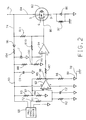
- the Figure 2 circuit has an integrated circuit containing an operational amplifier 92 and a voltage comparator 94.
- the pin numbers for these devices are shown in Figure 2.
- This integrated circuit may be a National Semiconductor type LM 2924 device.
- the operational amplifier 92 amplifies the output voltage of Hall effect device 68.
- the Hall effect device 68 has positive voltage applied thereto by conductor 93, resistor 194 (110 ohms) and diode 96.
- a Zener diode Z having a breakdown voltage of 8.2 volts is connected between conductor 93 and signal ground.
- a capacitor C1 of 35 microfarads is connected between conductor 93 and signal ground.
- the positive input terminal (pin 5) of operational amplifier 92 is connected to the conductor 72 and hence to the output of Hall effect device 68 by a 75K resistor R1. Resistor R2 (75K) and capacitor C2 (0.01 microfarad) are connected between the positive input terminal of operational amplifier 92 and signal ground.
- Operational amplifier 92 is further connected to 150K resistors R3 and R4, 75K resistor R5 and 3K resistor R6. Resistors R3 and R4 form a voltage divider having a junction 97 connected to the negative input terminal (pin 6) of operational amplifier 92. The output of operational amplifier 92 is at junction 98 (pin 7).
- Operational amplifier 92 is designed for unity gain in the differential channel and high common mode rejection in the common mode channels. This allows processing the output signal of Hall effect device 68 while providing good rejection to thermal drift.
- the negative input terminal (pin 2) of voltage comparator 94 is connected to the output of operational amplifier 92 via a 750 ohm resistor R7.
- the positive input terminal (pin 3) of voltage comparator 94 is connected to junction 100 between resistors R8 (59K) and R9 (750 ohms). Also connected to voltage comparator 94 are resistors R10 (2.7M) and R11 (4.7K).
- the output of voltage comparator 94 (pin 1) is connected to the gate G of FET 82 by conductor 80.
- the voltage divider resistors R8 and R9 provide a reference voltage at junction 100 that is applied to the positive input terminal (pin 3) of voltage comparator 94.
- the voltage at the negative input terminal (pin 2) of voltage comparator 94 varies in accordance with variation in the output voltage of Hall effect device 68.
- the load proportioning control of this invention operates to sense the output current I10 and I30 of generators 10 and 30. If there is a difference, for example I10, being greater than I30, the circuit controls the field current of generator 30 such that its output current will be increased until the magnitude of I30 substantially equals I10. The current output of generator 30 accordingly is slaved to the prevailing current output of generator 10. Putting it another way, the output current of generator 30 follows or tracks the output current of generator 10. It should be apparent that the generator 30 does not have a voltage regulator like the voltage regulator 54 that regulates the output voltage of generator 10.
- generators 10 and 30 are supplying output currents I10 and I30 and that I10 is greater than I30.
- the flux generated in toroid 64 will be related to the difference in the current levels of I10 and I30.
- the net flux that is applied to Hall effect device 68 will cause it to develop an output voltage that is a function of the difference in output currents I10 and I30.
- This voltage is applied to operational amplifier 92 and its output will be a voltage that is a function of the difference in the output currents I10 and I30.
- the output voltage of operational amplifier 92 is applied to one input terminal (pin 2) of voltage comparator 94.
- This voltage comparator 94 compares this voltage with a reference voltage applied to pin 3 from junction 100.
- the circuit is arranged such that when the voltage applied to pin 2 of voltage comparator 94 is higher than the reference voltage, the output of voltage comparator 94 goes low, or in other words, connects conductor 80 to signal ground which drives the gate G of FET 82 low which in turn causes FET 82 to be biased conductive between its source and drain thereby energizing field winding 32 of generator 30 from conductor 84. With the field winding 32 energized, the output current I30 will start increasing, causing the voltage applied to the negative input terminal (pin 2) of voltage comparator 94 to start decreasing.
- the output current I30 of generator 30 is controlled such that it follows and substantially equals output current I10. This occurs because there is a one-to-one turns ratio between the flux developed in toroid 64 and the turns of power supply conductors 28 and 44 that pass through the toroid 64.
- the straight conductor portions that pass through toroid 64 can be considered as one turn and there accordingly is a one-to-one turns ratio.
- the turns ratio can be made other than one-to-one so that the output currents I10 and I30 would not be substantially equal but rather would have a predetermined relationship or ratio.
- power supply conductor 44 instead of having one turn has two turns so that there is now a two-to-one turns ratio between power supply conductor 44 and power supply conductor 28.
Landscapes
- Engineering & Computer Science (AREA)
- Power Engineering (AREA)
- Control Of Eletrric Generators (AREA)
Claims (9)
- Appareil avec deux générateurs pour appliquer un courant électrique à une charge électrique (50, 52) comprenant un premier générateur (10) ayant un enroulement de sortie (14) et un enroulement de champ (12); un second générateur (30) ayant un enroulement de sortie (34) et un enroulement de champ (32); un moyen (46) reliant les enroulements de sortie (14, 34) des générateurs (10, 30) à la charge électrique (50, 52) de telle sorte que chaque générateur applique un courant (I10, I30) à la charge électrique et de telle sorte que le courant appliqué à la charge électrique soit sensiblement égal à la somme des courants de sortie (I10, I30) des générateurs (10, 30); et un régulateur de tension (54) connecté à l'enroulement de champ (12) du premier générateur (10) comprenant un moyen détecteur de tension détectant la tension aux bornes de la charge électrique, le régulateur de tension (54) fonctionnant pour commander le courant de champ de l'enroulement de champ (12) du premier générateur (10) de telle sorte que la tension de sortie du premier générateur soit régulée à une valeur prédéterminée; caractérisé par un moyen (64) de détection de courant fonctionnant pour détecter les courants de sortie (I10, I30) des générateurs (10, 30), le moyen (64) de détection de courant comprenant un moyen de développement (68) pour développer un signal électrique qui est une fonction des intensités relatives des courants de sortie (I10, I30) des générateurs (10, 30), et des moyens de commande (70, 82) sensibles au signal électrique pour commander le courant de champ de l'enroulement de champ (32) du second générateur (30) de telle sorte que le courant de sortie (I30) du second générateur (30) suive le courant de sortie (I10) du premier générateur (10) et de telle sorte qu'il y ait une relation prédéterminée entre les courants de sortie (I10, I30) des générateurs (10, 30).
- Appareil avec deux générateurs selon la revendication 1, dans lequel le moyen (64) de détection de courant a une construction et un agencement tels que le courant de sortie (I30) du second générateur (30) est régulé à une intensité qui est sensiblement égale à l'intensité du courant de sortie (I10) du premier générateur (10).
- Appareil avec deux générateurs selon la revendication 1 ou la revendication 2, dans lequel les premier et second générateurs (10, 30) sont des générateurs de courant alternatif, et dans lequel les courants de sortie (I10, I30) des générateurs sont développés par des moyens redresseurs (20, 38) connectés respectivement à un enroulement de sortie (14, 34) d'un générateur respectif.
- Appareil avec deux générateurs selon l'une quelconque des revendications 1 à 3, dans lequel les moyens de commande (70, 82) comportent un moyen de commutation semiconducteur (82) qui est branché en série avec l'enroulement de champ (32) du second générateur (30).
- Appareil avec deux générateurs selon l'une quelconque des revendications 1 à 4, dans lequel le moyen de développement comporte un dispositif (68) à effet Hall qui est traversé par un flux magnétique qui est développé par les courants de sortie (I10, I30) des premier et second générateurs (10, 30).
- Appareil avec deux générateurs selon la revendication 3, dans lequel la charge électrique comporte une batterie d'accumulateurs (50), dans lequel des moyens (28, 44, 46) relient les sorties des deux moyens redresseurs (20, 38) à la batterie d'accumulateurs de telle sorte que les deux moyens redresseurs (20, 38) puissent appliquer un courant de charge à la batterie d'accumulateurs, le moyen de détection de' la tension du régulateur de tension (54) étant connecté à la batterie d'accumulateurs pour détecter la tension aux bornes de la batterie d'accumulateurs (50).
- Appareil avec deux générateurs selon la revendication 4, dans lequel le moyen de commande (70) est couplé au moyen (64) de détection de courant et comporte des moyens (92, 94) pour rendre conducteur le moyen de commutation semiconducteur (82) lorsque les intensités relatives des courants de sortie (I10, I30) sont dans une première relation et pour rendre non conducteur le moyen de commutation semiconducteur (82) lorsque les intensités relatives des courants de sortie des générateurs (10, 30) sont dans une seconde relation qui est différente de la première relation.
- Appareil avec deux générateurs selon la revendication 7 qui est agencé de telle sorte que la première relation correspond à une condition de fonctionnement où le courant de sortie (I10) du premier générateur (10) est supérieur au courant de sortie (I30) du second générateur (30) et dans lequel la seconde relation correspond à une condition de fonctionnement où les courants de sortie desdits premier et second générateurs sont sensiblement égaux.
- Appareil avec deux générateurs selon la revendication 7 ou la revendication 8, dans lequel le moyen de commutation semiconducteur est un transistor à effet de champ (82).
Applications Claiming Priority (2)
| Application Number | Priority Date | Filing Date | Title |
|---|---|---|---|
| US190852 | 1988-05-06 | ||
| US07/190,852 US4829228A (en) | 1988-05-06 | 1988-05-06 | Dual generator electrical system |
Publications (3)
| Publication Number | Publication Date |
|---|---|
| EP0340913A2 EP0340913A2 (fr) | 1989-11-08 |
| EP0340913A3 EP0340913A3 (en) | 1990-11-28 |
| EP0340913B1 true EP0340913B1 (fr) | 1993-07-28 |
Family
ID=22703062
Family Applications (1)
| Application Number | Title | Priority Date | Filing Date |
|---|---|---|---|
| EP89303398A Expired - Lifetime EP0340913B1 (fr) | 1988-05-06 | 1989-04-06 | Appareil électrique avec deux générateurs |
Country Status (4)
| Country | Link |
|---|---|
| US (1) | US4829228A (fr) |
| EP (1) | EP0340913B1 (fr) |
| CA (1) | CA1286718C (fr) |
| DE (1) | DE68907779T2 (fr) |
Cited By (1)
| Publication number | Priority date | Publication date | Assignee | Title |
|---|---|---|---|---|
| CN105048907A (zh) * | 2015-07-03 | 2015-11-11 | 北京奥博汽车电子电器有限公司 | 一种具有管理功能的汽车发电机电压调节器 |
Families Citing this family (30)
| Publication number | Priority date | Publication date | Assignee | Title |
|---|---|---|---|---|
| US5013991A (en) * | 1989-04-27 | 1991-05-07 | Sure Power, Inc. | Multi-voltage alternator with integral bank switched bridge |
| US5254936A (en) * | 1992-09-14 | 1993-10-19 | General Motors Corporation | Dual generator electrical system |
| US5544484A (en) * | 1993-02-03 | 1996-08-13 | Nartron Corporation | Engine induction air driven alternator |
| US5600232A (en) * | 1994-06-17 | 1997-02-04 | Deere & Company | Alternator system for a vehicle |
| US5723972A (en) * | 1995-12-29 | 1998-03-03 | Bartol; Luis E. | Fail-safe common control of multiple alternators electrically connected in tandem parallel for producing high current |
| US5760507A (en) * | 1996-02-06 | 1998-06-02 | Ford Global Technologies, Inc. | Electrical generating system for a motor vehicle |
| US5739676A (en) * | 1996-11-04 | 1998-04-14 | Ford Motor Company | Multiple-alternator electrical system |
| US6369549B1 (en) | 1998-10-05 | 2002-04-09 | Ford Global Tech., Inc. | Motor vehicle electrical system with multiple generators |
| US6281664B1 (en) * | 1999-01-13 | 2001-08-28 | Honda Giken Kogyo Kabushiki Kaisha | Generator and generator apparatus |
| JP2000295827A (ja) * | 1999-04-01 | 2000-10-20 | Mitsubishi Electric Corp | 車両の電力供給システム |
| US7019495B2 (en) * | 2003-08-28 | 2006-03-28 | C.E. Neihoff & Co. | Inter-regulator control of multiple electric power sources |
| DE102004008433A1 (de) | 2004-02-19 | 2005-09-08 | Robert Bosch Gmbh | Vorrichtung zur Spannungsversorgung |
| DE102004051742A1 (de) * | 2004-10-23 | 2006-04-27 | Robert Bosch Gmbh | Vorrichtung mit mehreren parallel geschalteten Generatoren zur Spannungsversorgung |
| DE102005012273A1 (de) * | 2005-03-17 | 2006-09-21 | Robert Bosch Gmbh | Vorrichtung zur Spannungsversorgung der Verbraucher eines Kraftfahrzeug-Bordnetzes unter Verwendung von mehreren Generatoren |
| US7573155B2 (en) * | 2005-04-19 | 2009-08-11 | Remy Inc. | Systems and methods for distributing loads |
| US7456616B2 (en) * | 2005-08-04 | 2008-11-25 | Remy Technologies, L.L.C. | Current sensor for electric machine control |
| US7439713B2 (en) | 2006-09-20 | 2008-10-21 | Pratt & Whitney Canada Corp. | Modulation control of power generation system |
| US7405542B1 (en) * | 2006-12-20 | 2008-07-29 | The Boeing Company | Generator synchronization method on a common drive source and apparatus therefor |
| US20090237038A1 (en) * | 2007-04-11 | 2009-09-24 | Ron Heidebrink | Double alternator and electrical system |
| US7291933B1 (en) * | 2007-04-11 | 2007-11-06 | Ron Heidebrink | Double alternator and electrical system for a vehicle |
| JP4849480B2 (ja) * | 2008-03-03 | 2012-01-11 | 三菱電機株式会社 | 車両用発電制御装置 |
| US8279648B2 (en) * | 2008-03-20 | 2012-10-02 | Pratt & Whitney Canada Corp. | Power inverter and method |
| GB0806491D0 (en) * | 2008-04-10 | 2008-05-14 | Rolls Royce Plc | A method and system for electrical power generation |
| GB0806492D0 (en) * | 2008-04-10 | 2008-05-14 | Rolls Royce Plc | A generating system |
| JP4949328B2 (ja) * | 2008-06-24 | 2012-06-06 | 本田技研工業株式会社 | 発電機の並列運転接続装置 |
| US7990112B2 (en) * | 2008-08-14 | 2011-08-02 | Honeywell International Inc. | Adaptive field control of a variable frequency synchronous generator |
| US8072092B2 (en) * | 2009-07-24 | 2011-12-06 | C.E. Niehoff & Co. | System and method for sequentional electrical power delivery from two generators in a vehicle electrical system |
| US9219294B2 (en) | 2012-08-22 | 2015-12-22 | Eric D. Albsmeier | Power management system that changes the operating conditions of a battery charger |
| US9331498B2 (en) * | 2012-09-07 | 2016-05-03 | Kohler Co. | Power generation system that provides efficient battery charger selection |
| US8816650B2 (en) * | 2012-11-19 | 2014-08-26 | Hamilton Sundstrand Corporation | Modulating current in a dual generator system |
Family Cites Families (12)
| Publication number | Priority date | Publication date | Assignee | Title |
|---|---|---|---|---|
| US2504768A (en) * | 1948-05-19 | 1950-04-18 | Westinghouse Electric Corp | Electronic load proportioning circuit |
| DE1002851B (de) * | 1952-11-12 | 1957-02-21 | Eisen & Stahlind Ag | Stromerzeugungsanlage mit Akkumulatorenbatterie, insbesondere Zugbeleuchtungsanlage |
| US3793544A (en) * | 1972-02-10 | 1974-02-19 | Caterpillar Tractor Co | Multiple winding, multiple voltage, alternator system |
| US4262209A (en) * | 1979-02-26 | 1981-04-14 | Berner Charles A | Supplemental electrical power generating system |
| US4336485A (en) * | 1979-04-26 | 1982-06-22 | Stroud Lebern W | Dual alternator feedback system |
| US4347473A (en) * | 1979-04-26 | 1982-08-31 | Stroud Lebern W | Dual alternator power system for motor vehicle |
| US4348628A (en) * | 1980-06-20 | 1982-09-07 | Loucks Carl C | Electric motor alternating power supply for vehicles |
| US4539515A (en) * | 1982-03-18 | 1985-09-03 | Mitsubishi Denki Kabushiki Kaisha | Vehicular direct-current three-wire electric system |
| JPS58201544A (ja) * | 1982-05-20 | 1983-11-24 | 三菱電機株式会社 | マイクロコンピユ−タ付車両用直流三線式回路装置 |
| US4509005A (en) * | 1982-07-15 | 1985-04-02 | Stroud Lebern W | Dual alternator system |
| FR2531584B1 (fr) * | 1982-08-04 | 1986-08-14 | Paris & Du Rhone | Alternateur triphase avec double enroulement d'induit |
| JPH0810999B2 (ja) * | 1983-06-01 | 1996-01-31 | 本田技研工業株式会社 | 車両用発電機の制御装置 |
-
1988
- 1988-05-06 US US07/190,852 patent/US4829228A/en not_active Expired - Fee Related
- 1988-12-01 CA CA000584703A patent/CA1286718C/fr not_active Expired - Lifetime
-
1989
- 1989-04-06 DE DE89303398T patent/DE68907779T2/de not_active Expired - Fee Related
- 1989-04-06 EP EP89303398A patent/EP0340913B1/fr not_active Expired - Lifetime
Cited By (2)
| Publication number | Priority date | Publication date | Assignee | Title |
|---|---|---|---|---|
| CN105048907A (zh) * | 2015-07-03 | 2015-11-11 | 北京奥博汽车电子电器有限公司 | 一种具有管理功能的汽车发电机电压调节器 |
| CN105048907B (zh) * | 2015-07-03 | 2017-06-06 | 北京奥博汽车电子电器有限公司 | 一种具有管理功能的汽车发电机电压调节器 |
Also Published As
| Publication number | Publication date |
|---|---|
| US4829228A (en) | 1989-05-09 |
| DE68907779D1 (de) | 1993-09-02 |
| CA1286718C (fr) | 1991-07-23 |
| EP0340913A2 (fr) | 1989-11-08 |
| DE68907779T2 (de) | 1993-11-04 |
| EP0340913A3 (en) | 1990-11-28 |
Similar Documents
| Publication | Publication Date | Title |
|---|---|---|
| EP0340913B1 (fr) | Appareil électrique avec deux générateurs | |
| US5254936A (en) | Dual generator electrical system | |
| US4743830A (en) | Dual voltage electrical system | |
| US4491779A (en) | Motor vehicle electrical system | |
| US3668514A (en) | Dual voltage power system for use with vehicle alternators and the like | |
| EP0545454A2 (fr) | Régulateur de tension | |
| US4335344A (en) | Voltage regulator for a controlled field generator | |
| US5266882A (en) | Control device for an alternating current generator of a vehicle | |
| US4409539A (en) | Self-excitation for an alternator of the low-carbon steel rotor type | |
| CA1246666A (fr) | Regulateur de tension pour generatrice | |
| US3316416A (en) | Vehicle electrical system | |
| US5493202A (en) | Voltage regulator device for vehicular AC generator | |
| US6696773B2 (en) | Vehicle generator control system | |
| US3510752A (en) | Transistor voltage regulating system for generators having main and reverse field windings | |
| US4449089A (en) | Battery chargers | |
| US3544881A (en) | Transistor voltage and current regulating system for an alternating current generator | |
| US6670792B1 (en) | Alternator regulation circuit having parallel field coil current re-circulation | |
| US4517507A (en) | Multiple output alternator system | |
| US3185916A (en) | Voltage regulator with load compensation | |
| US2996655A (en) | Current limiter for generators | |
| US3835363A (en) | Motor vehicle power supply system | |
| US3350619A (en) | Battery charging circuit responsive to generator output voltage and current | |
| US5289105A (en) | Voltage-regulator circuit for a system for recharging the battery of a motor vehicle | |
| US3443200A (en) | Excitation system for generators | |
| US3082370A (en) | Generating system regulation |
Legal Events
| Date | Code | Title | Description |
|---|---|---|---|
| PUAI | Public reference made under article 153(3) epc to a published international application that has entered the european phase |
Free format text: ORIGINAL CODE: 0009012 |
|
| AK | Designated contracting states |
Kind code of ref document: A2 Designated state(s): DE FR GB IT |
|
| PUAL | Search report despatched |
Free format text: ORIGINAL CODE: 0009013 |
|
| AK | Designated contracting states |
Kind code of ref document: A3 Designated state(s): DE FR GB IT |
|
| 17P | Request for examination filed |
Effective date: 19910116 |
|
| 17Q | First examination report despatched |
Effective date: 19921106 |
|
| ITF | It: translation for a ep patent filed | ||
| GRAA | (expected) grant |
Free format text: ORIGINAL CODE: 0009210 |
|
| AK | Designated contracting states |
Kind code of ref document: B1 Designated state(s): DE FR GB IT |
|
| REF | Corresponds to: |
Ref document number: 68907779 Country of ref document: DE Date of ref document: 19930902 |
|
| ET | Fr: translation filed | ||
| ITTA | It: last paid annual fee | ||
| PLBE | No opposition filed within time limit |
Free format text: ORIGINAL CODE: 0009261 |
|
| STAA | Information on the status of an ep patent application or granted ep patent |
Free format text: STATUS: NO OPPOSITION FILED WITHIN TIME LIMIT |
|
| 26N | No opposition filed | ||
| PGFP | Annual fee paid to national office [announced via postgrant information from national office to epo] |
Ref country code: GB Payment date: 19960402 Year of fee payment: 8 |
|
| PGFP | Annual fee paid to national office [announced via postgrant information from national office to epo] |
Ref country code: FR Payment date: 19960426 Year of fee payment: 8 |
|
| PGFP | Annual fee paid to national office [announced via postgrant information from national office to epo] |
Ref country code: DE Payment date: 19960529 Year of fee payment: 8 |
|
| PG25 | Lapsed in a contracting state [announced via postgrant information from national office to epo] |
Ref country code: GB Effective date: 19970406 |
|
| GBPC | Gb: european patent ceased through non-payment of renewal fee |
Effective date: 19970406 |
|
| PG25 | Lapsed in a contracting state [announced via postgrant information from national office to epo] |
Ref country code: FR Free format text: LAPSE BECAUSE OF NON-PAYMENT OF DUE FEES Effective date: 19971231 |
|
| PG25 | Lapsed in a contracting state [announced via postgrant information from national office to epo] |
Ref country code: DE Free format text: LAPSE BECAUSE OF NON-PAYMENT OF DUE FEES Effective date: 19980101 |
|
| REG | Reference to a national code |
Ref country code: FR Ref legal event code: ST |
|
| PG25 | Lapsed in a contracting state [announced via postgrant information from national office to epo] |
Ref country code: IT Free format text: LAPSE BECAUSE OF NON-PAYMENT OF DUE FEES Effective date: 20050406 |