EP0340937B1 - Vorrichtung zum Anbringen einer Hebeeinrichtung an einen Container oder dergl. - Google Patents
Vorrichtung zum Anbringen einer Hebeeinrichtung an einen Container oder dergl. Download PDFInfo
- Publication number
- EP0340937B1 EP0340937B1 EP89303768A EP89303768A EP0340937B1 EP 0340937 B1 EP0340937 B1 EP 0340937B1 EP 89303768 A EP89303768 A EP 89303768A EP 89303768 A EP89303768 A EP 89303768A EP 0340937 B1 EP0340937 B1 EP 0340937B1
- Authority
- EP
- European Patent Office
- Prior art keywords
- container
- probe member
- housing
- end wall
- aperture
- Prior art date
- Legal status (The legal status is an assumption and is not a legal conclusion. Google has not performed a legal analysis and makes no representation as to the accuracy of the status listed.)
- Expired - Lifetime
Links
- 230000007246 mechanism Effects 0.000 title claims abstract description 15
- 239000000523 sample Substances 0.000 claims abstract description 25
- 230000000717 retained effect Effects 0.000 claims abstract description 6
- 238000000034 method Methods 0.000 description 2
- 230000004075 alteration Effects 0.000 description 1
- 238000005266 casting Methods 0.000 description 1
- 238000010276 construction Methods 0.000 description 1
- 230000001419 dependent effect Effects 0.000 description 1
- 230000000694 effects Effects 0.000 description 1
- 238000010348 incorporation Methods 0.000 description 1
- 238000003780 insertion Methods 0.000 description 1
- 230000037431 insertion Effects 0.000 description 1
- 230000000284 resting effect Effects 0.000 description 1
Images


Classifications
-
- B—PERFORMING OPERATIONS; TRANSPORTING
- B66—HOISTING; LIFTING; HAULING
- B66C—CRANES; LOAD-ENGAGING ELEMENTS OR DEVICES FOR CRANES, CAPSTANS, WINCHES, OR TACKLES
- B66C1/00—Load-engaging elements or devices attached to lifting or lowering gear of cranes or adapted for connection therewith for transmitting lifting forces to articles or groups of articles
- B66C1/10—Load-engaging elements or devices attached to lifting or lowering gear of cranes or adapted for connection therewith for transmitting lifting forces to articles or groups of articles by mechanical means
- B66C1/62—Load-engaging elements or devices attached to lifting or lowering gear of cranes or adapted for connection therewith for transmitting lifting forces to articles or groups of articles by mechanical means comprising article-engaging members of a shape complementary to that of the articles to be handled
- B66C1/66—Load-engaging elements or devices attached to lifting or lowering gear of cranes or adapted for connection therewith for transmitting lifting forces to articles or groups of articles by mechanical means comprising article-engaging members of a shape complementary to that of the articles to be handled for engaging holes, recesses, or abutments on articles specially provided for facilitating handling thereof
- B66C1/663—Load-engaging elements or devices attached to lifting or lowering gear of cranes or adapted for connection therewith for transmitting lifting forces to articles or groups of articles by mechanical means comprising article-engaging members of a shape complementary to that of the articles to be handled for engaging holes, recesses, or abutments on articles specially provided for facilitating handling thereof for containers
-
- B—PERFORMING OPERATIONS; TRANSPORTING
- B60—VEHICLES IN GENERAL
- B60P—VEHICLES ADAPTED FOR LOAD TRANSPORTATION OR TO TRANSPORT, TO CARRY, OR TO COMPRISE SPECIAL LOADS OR OBJECTS
- B60P1/00—Vehicles predominantly for transporting loads and modified to facilitate loading, consolidating the load, or unloading
- B60P1/64—Vehicles predominantly for transporting loads and modified to facilitate loading, consolidating the load, or unloading the load supporting or containing element being readily removable
- B60P1/6418—Vehicles predominantly for transporting loads and modified to facilitate loading, consolidating the load, or unloading the load supporting or containing element being readily removable the load-transporting element being a container or similar
- B60P1/6463—Vehicles predominantly for transporting loads and modified to facilitate loading, consolidating the load, or unloading the load supporting or containing element being readily removable the load-transporting element being a container or similar fitted with articulated beams for longitudinal displacement of the container
Definitions
- the present invention relates to devices for attaching lifting mechanisms to containers or the like, and in particular to containers provided with pre-formed apertures therein, such as those in the corner fittings of standard freight containers.
- Standard freight containers are provided with corner fittings each of which comprises a hollow, generally box-shaped component provided with apertures in the outwardly facing walls thereof for receiving therein releasable securing means.
- corner fittings each of which comprises a hollow, generally box-shaped component provided with apertures in the outwardly facing walls thereof for receiving therein releasable securing means.
- the upper corner fittings are such as to permit lifting and manoeuvring of the containers.
- such lifting is usually achieved using a spreader equipped either with built-in twistlocks adapted to be received in the apertures in the upper walls of the upper corner fittings or with hooks which pass through the apertures in the upper walls of the upper corner fittings and through the apertures in the end walls of said corner fittings, said latter apertures commonly being known as 'hook holes'.
- the interiors of the upper corner fittings between the apertures in the upper walls and the end walls are shaped to accommodate the hooks, as are the hook holes themselves.
- Said hook holes are each of only slightly asymmetrical shape with-no significant difference between the lengths of the major and minor axes and with little flat purchase area therearound within the fitting.
- a device for attaching a lifting mechanism to a container or the like provided with an aperture through an end wall thereof comprising a probe member adapted to be secured to the lifting mechanism and including a head portion for location through said aperture in the end wall of the container and into the container, said head portion being provided with a surface thereon which, with the device in its operative position, abuts a region of the inner face of the end wall of the container bounding said aperture, the probe member further including a body portion projecting from the container and provided with a surface thereon which, with the device in its operative position, abuts a substantially diametrically opposed region of the outer face of the end wall of the container bounding said aperture, the arrangement being such that, with the device in its operative position and on raising of the lifting mechanism, the probe member engages the undersurface of the upper regions of the aperture through the end wall of the container and is retained in said operative position by co-operation between said surfaces on the head portion and on the body portion
- a preferred application of the device of the invention enables attachment of a lifting mechanism to standard I.S.O. freight containers by way of the end apertures in the conventional upper corner fittings provided on such containers.
- the invention is particularly suited to incorporation on an adaptor frame as disclosed in our co-pending European patent application no. 87.310910.2, this frame enabling conventional I.S.O. containers to be handled by conventional hook-lift type vehicles without any alteration to the containers or to the vehicles.
- the adaptor frame is attachable to, to be movable by, the hydraulically-operated lift arrangement mounted on the chassis of the hook-lift type vehicle, the frame including devices according to the first aspect of the invention mounted thereon for co-operation with the upper corner fittings of one end of a freight container whereby said frame can be secured to the container.
- means for adapting a hook-lift type vehicle having a hydraulically-operated lift arrangement on the chassis thereof, to load and unload freight containers having conventional corner fittings at the corners thereof
- the means comprising an adaptor frame for attachment to, to be movable by, the lift arrangement, said adaptor frame including a pair of devices as defined above for co-operation one with each of the two upper corner fittings of the container to secure said frame to the container.
- the adaptor frame comprises a body portion to which the lift arrangement of the vehicle is attached, and a pair of adjustable arm members each of which is pivotally mounted to the body portion, said arm members each carrying a device as defined above.
- Each device may comprise an elongate housing rigidly secured to the associated arm member, the body portion of the probe member being mounted in said housing with the head portion of the probe member projecting from the housing, the probe member being axially fixed relative to the housing but selectively rotatable relative thereto.
- the housing is of tubular shape and the body portion includes a diametrical flange adapted to assist location of the probe member within the housing.
- the probe member is rotatable within the housing between first and second angularly displaced operative positions, one associated with the arm member in an uppermost position aligning the device with the upper corner fitting of a full height freight container, and the other associated with the arm member in a lowermost position aligning the device with the upper corner fitting of a half height freight container.
- the device may further comprise adjustable stop means to locate the probe member in a chosen operative position.
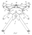
- an adaptor frame is indicated generally at 2 and includes a central body portion 4 provided with a lifting hook bar 6.
- a pair of arms 8,10 are rigidly secured to, to extend downwardly and outwardly from, the body portion 4, the free end of each arm 8,10 carrying a twistlock 12, the twistlocks 12 being spaced 2.44 metres (8 feet) apart for cooperation with the lower corner fittings of any standard I.S.O. container.
- a pair of upper arms 14,16 are each mounted to the body portion 4 to be pivotal relative thereto about associated pivot points 18,20,each arm 14,16 being provided with a slot therein in which the pivot points 18,20 are received whereby each arm 14,16 can also move axially thereof relative to the associated pivot point 18,20 and to the body portion 4.
- arms shown in dotted lines at 14 a , and 16 a are positioned to suit, typically, a 1.22 metres (4 feet) high container, while those shown in dotted lines at 14 b and 16 b are positoned to suit, typically, a container 2.59 metres (8 feet 6 inches) high.
- a pair of removable, rigid stays 22,24 may extend between the body portion 4 and each arm 14,16, one end of each stay being pivotally mounted at 26 to the body portion 4 and the other end of each stay being pivotally mounted at 28 to the associated arm.
- the pivotal mountings at 28 are each such as to permit limited linear movement of the arms 14,16 relative to the associated stays 22,24.
- the free ends of the arms 14,16 have each carried a twistlock thereon adapted to be located in the upper corner fitting of an associated container, with the twistlocks 12 being located in the lower corner fittings of the container whereby the adaptor frame is secured to said container.
- twistlocks require manual insertion into the associated corner fittings, and, bearing in mind these twistlocks can be located at heights of up to 2.59 metres (8 feet 6 inches), it will be appreciated that there is an inherent safety problem in such an arrangement.
- the invention provides devices to replace the upper twistlocks and which are such that they can be inserted into the upper corner fittings of the container by appropriate manoeuvring of the adaptor frame and without the necessity for personal attendance at the upper corner fittings.
- an attachment device according to the invention is indicated generally at 30 and comprises an open-ended tubular housing 32 welded or otherwise secured to the free end of an arm 14 or 16 of the adaptor frame.
- a hook member or probe member 34 which comprises a body portion 36 extending centrally the length of the housing 32 and carrying an end bar 38 extending substantially diametrically of the housing 32 and adapted to engage the rear end of said housing to determine the operative axial position of the hook member within the housing 32.
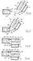
- the front end of the hook member 34 comprises a head portion 40 projecting from the housing 32 and of generally hook-shape including a recess 42 bounded by an upstanding, rearwardly-facing abutment surface 44.
- the body portion 36 further includes an increased diameter portion 46 for location in the front end of the housing 32 and in which is formed a groove 48 adapted to receive therein the free edge of an arcuate retaining plate 50 welded to the front end of the housing 32, said plate 50, together with the end bar 38, locating the hook member axially relative to the housing 32.
- the body portion 36 of the hook member 34 includes a pair of lateral flanges 52 projecting therefrom radially of the housing 32 serving to locate the body portion 36 within the housing 32 and facilitating rotation of the hook member 34 within said housing 32.
- the increased diameter portion 46 of the body portion 36 includes an upstanding, forwardly-facing abutment surface 54 thereon for reasons which will become apparent.
- the configuration of the hook member 34 is such that it can be assembled into the housing 32 by feeding the head portion 40 through the housing from the rear end thereof until the end bar 38 abuts said rear end of the housing, the retaining plate 50 then being welded to the housing 32 whereby axial movement of the hook member 34 relative to the housing 32 is prevented but rotation is permitted.
- the arm members 14,16 to which the devices 30 are attached have two operative positions, one associated with full height containers and the other with half height containers.
- the hook member 34 must be capable of adopting the operative position shown in Fig .2 regardless of the angular position of the arm member 14 or 16 and therefore of the housing 32. Hence the requirement that the hook member 34 is rotatable relative to the housing 32.
- the device further includes means for locating the hook member in its operative position relative to the housing 32 for each position 14 a , 16 a and 14 b , 16 b of the arm members 14,16.
- Fig. 4 shows the arm member 14 in its upper position.
- the retaining plate 50 includes end portions 55,56 providing stop surfaces 58,60 thereon angularly spaced by about 110°.
- a movable stop plate 62 is pivotal on a pin 64 welded to the housing 32 and is retained in an operative position by means of an axially movable pin 66 mounted in a bracket 68 on the housing 32, the pin 66 extending through a hole in the plate 62 and being retained by a spring 'R' clip 70 located through a diametrical bore in the end of the pin 66.
- the pin 66 carries a lug 72 secured thereto which prevents removal of the pin 66 from the bracket 68 but permits sufficient freedom of movement of the pin into and out of the movable stop plate.
- the stop plate 62 includes abutment surfaces 74, 76 thereon.
- the pin 66 is pushed back through the plate 62 and the spring clip 70 is inserted through the pin 66 to secure the plate in its operative position.
- the head portion 40 of the hook member 34 is then retained in its operative position between the surfaces 60,76 again with about 20° angular movement available thereto.
- the described arrangement operates as follows. With the devices 30 welded to the arm members 14,16, the hook members 34 are correctly positioned within the housings 32 dependant upon whether a full height container or a half height container is to be lifted by the frame 2 - i.e. dependent upon whether the arm members are in the positions 14 a , 16 a or 14 b , 16 b in Fig. 1.
- the adaptor frame 2 which is resting substantially vertically on the ground as seen in Fig. 10, is engaged onto the hydraulically-operated lift arrangement 86 of a hook-lift type vehicle 88 by means of the lifting bar 6, and the frame 2 is manoeuvred by the lift arrangement 86 to a position with the upper regions thereof angled forwardly of the lower regions. In this position, the head portions 40 of the devices 30 extend downwardly and forwardly as shown in Fig. 6.
- the lift arrangement 86 is further manoeuvred until the head portions 40 are aligned with the apertures 78 in the end walls 80 of the associated corner fittings 82 of a container 90, the head portions 40 then entering said apertures 78 as seen in Fig. 7.
- the frame 2 is returned to its vertical disposition whereby the surfaces 44 of the head portions 40 engage behind the inner faces of the upper regions of the end walls 80 of the corner fittings 82 and the surfaces 56 of the hook members 34 abut the outer faces of the lower regions of said end walls 80.
- the lower twistlocks 12 are manually engaged into the front apertures of the bottom corner fittings 92 of the container 90 and are locked therein to complete the attachment of the frame 2 to the container 90.
- the container 90 is then raised by the lift arrangement 86 and is loaded onto the vehicle 88 in the relatively conventional manner associated with the self-loading of dedicated hook-lift flatracks, an intermediate stage of the loading procedure being shown in Fig. 11.
- the upper regions of the end walls 80 of the upper corner fittings 82 seat in the recesses 42 in the head portions 40 of the devices 30, with the surfaces 44, 54 of the hook members 34 maintaining bearing contact with the associated regions of the end walls 80 of said fittings 82.
- the free end of the head portion 40 of the hook member 34 projects through the aperture 84 in the top wall of the corner fitting as seen in Fig. 9.
- the configuration of the hook members 34 is such that a positive attachment of the adaptor frame 2 to a container 90 is effected through the apertures in the end walls of the upper corner fittings, the surfaces 44, 54 of the hook members creating bearing areas for abutment with the limited areas available on the end walls of said fittings, while the head portions 40, once within the corner fittings 82, cannot be removed or withdrawn therefrom other than by appropriate manoeuvring of said head portions - each head portion 40 is thus self-locking within the corner fitting 82 behind the so-called 'hook hole arch' in the end wall of the fitting.
- the limited rotational movement of the hook member 34 in the housing 32 between the surfaces 58,74 or 60,76 enables the hook member 34 to line itself up relative to the associated corner fitting 82 on initial lifting of the container 90 and also accommodates distortion and damage that may have occurred to the container.
- attachment devices of the invention could be mounted on other lifting mechanisms, while the precise construction of the devices could vary from that illustrated.
Landscapes
- Engineering & Computer Science (AREA)
- Mechanical Engineering (AREA)
- Transportation (AREA)
- Load-Engaging Elements For Cranes (AREA)
- Supplying Of Containers To The Packaging Station (AREA)
- Spinning Or Twisting Of Yarns (AREA)
- Spray Control Apparatus (AREA)
- Auxiliary Devices For And Details Of Packaging Control (AREA)
- Blow-Moulding Or Thermoforming Of Plastics Or The Like (AREA)
- Filling Of Jars Or Cans And Processes For Cleaning And Sealing Jars (AREA)
- Lining Or Joining Of Plastics Or The Like (AREA)
Claims (8)
Priority Applications (1)
| Application Number | Priority Date | Filing Date | Title |
|---|---|---|---|
| AT89303768T ATE78765T1 (de) | 1988-05-04 | 1989-04-17 | Vorrichtung zum anbringen einer hebeeinrichtung an einen container oder dergl. |
Applications Claiming Priority (2)
| Application Number | Priority Date | Filing Date | Title |
|---|---|---|---|
| GB888810487A GB8810487D0 (en) | 1988-05-04 | 1988-05-04 | Device for attaching lifting mechanism to container &c |
| GB8810487 | 1988-05-04 |
Publications (2)
| Publication Number | Publication Date |
|---|---|
| EP0340937A1 EP0340937A1 (de) | 1989-11-08 |
| EP0340937B1 true EP0340937B1 (de) | 1992-07-29 |
Family
ID=10636306
Family Applications (1)
| Application Number | Title | Priority Date | Filing Date |
|---|---|---|---|
| EP89303768A Expired - Lifetime EP0340937B1 (de) | 1988-05-04 | 1989-04-17 | Vorrichtung zum Anbringen einer Hebeeinrichtung an einen Container oder dergl. |
Country Status (6)
| Country | Link |
|---|---|
| US (1) | US4968080A (de) |
| EP (1) | EP0340937B1 (de) |
| AT (1) | ATE78765T1 (de) |
| DE (1) | DE68902268T2 (de) |
| ES (1) | ES2035555T3 (de) |
| GB (1) | GB8810487D0 (de) |
Families Citing this family (14)
| Publication number | Priority date | Publication date | Assignee | Title |
|---|---|---|---|---|
| NL193992C (nl) * | 1990-08-01 | 2001-04-03 | Nch Hydraul Systemen Bv | Vrachtwagen met een inrichting om een zeecontainer op te nemen of af te zetten, alsmede koppelorgaan hiervoor. |
| US5431471A (en) * | 1992-09-16 | 1995-07-11 | Mi-Jack Products, Inc. | Side fitting connection apparatus for lifting trailers and containers |
| WO1994013574A1 (en) * | 1992-09-16 | 1994-06-23 | Mi-Jack Products, Inc. | Side latch interconnect apparatus and method for transporting a container |
| USD345121S (en) | 1992-10-15 | 1994-03-15 | Baumann James A | Hoisting fitting for removable truck containers |
| FR2750088B1 (fr) * | 1996-06-21 | 1998-09-11 | Marrel Sa | Vehicule equipe d'un dispositif de manutention a bras de levage hydraulique |
| US5803699A (en) * | 1996-11-12 | 1998-09-08 | Capitol Tool And Die Co. | Apparatus and method for loading and unloading containers |
| AU725211B2 (en) * | 1996-11-15 | 2000-10-05 | Ausco Modular Pty Limited | A safety lifting connection system |
| FR2774639B1 (fr) * | 1998-02-09 | 2000-05-12 | Marrel Sa | Dispositif, appareil et procede pour permettre a un vehicule de prendre ou de poser au sol une charge presentant un moyen de prehension a l'avant |
| US6883815B2 (en) | 2002-06-13 | 2005-04-26 | Oshkosh Truck Corporation | Fire-fighting vehicle |
| US8215892B2 (en) * | 2007-03-30 | 2012-07-10 | Oshkosh Corporation | Arrangement for moving a cargo-carrying apparatus on a vehicle |
| US11042745B2 (en) | 2018-04-23 | 2021-06-22 | Oshkosh Corporation | Refuse vehicle control system |
| FR3104562B1 (fr) * | 2019-12-16 | 2021-11-19 | Guima Palfinger | Support de levage de conteneur par des orifices supérieurs du conteneur |
| FI129458B (en) * | 2020-06-18 | 2022-02-28 | Contle Oy | Loading arrangement for loading and unloading load units on and off a vehicle |
| US12059991B2 (en) * | 2022-05-23 | 2024-08-13 | Phase Ii Enterprises, Inc. | Method and apparatus for translating dumpsters |
Family Cites Families (15)
| Publication number | Priority date | Publication date | Assignee | Title |
|---|---|---|---|---|
| US1454587A (en) * | 1922-10-25 | 1923-05-08 | Wright Mfg Company | Coupling |
| US3365229A (en) * | 1965-12-30 | 1968-01-23 | Pullman Inc | Container coupling means |
| FR2344417A1 (fr) * | 1976-03-19 | 1977-10-14 | Bennes Marrel | Semi-remorque perfectionnee pour la manutention et le transport de caissons ou containers normalises |
| FR2358352A1 (fr) * | 1976-07-13 | 1978-02-10 | Bennes Marrel | Container normalise pouvant etre manipule a l'aide d'un camion pourvu d'une potence de manutention |
| US4068878A (en) * | 1976-09-28 | 1978-01-17 | The United States Of America As Represented By The Secretary Of The Navy | Container lift coupling |
| SE402556B (sv) * | 1976-10-20 | 1978-07-10 | Bygg Och Transportekonomie Ab | Anordning vid sadana lyfttruckar for hantering av storlastbehallare, vilka bestar av en bygelvagn med tva lengsgaende rambalkar |
| US4153169A (en) * | 1978-05-08 | 1979-05-08 | The United States Of America As Represented By The Secretary Of The Army | Loading-unloading capability for cargo box transport vehicle |
| US4231709A (en) * | 1978-12-15 | 1980-11-04 | Craig Systems Corporation | Demountable transporter for containers |
| SU1158473A1 (ru) * | 1981-07-16 | 1985-05-30 | Vaninskij Morskoj Torgovyj Por | "гpузoпoд'emhaя tpabepca" |
| DE3129105A1 (de) * | 1981-07-23 | 1983-02-10 | Drehtainer Container-Technik GmbH & Co, 2000 Hamburg | Vorrichtung zum ankoppeln von normbehaeltern |
| US4452555A (en) * | 1981-09-18 | 1984-06-05 | The Union Corporation | Attachment apparatus |
| US4824318A (en) * | 1984-04-04 | 1989-04-25 | Glenn Warner | Quick disconnect container carrier |
| DE3621648C2 (de) * | 1986-06-27 | 1994-06-23 | Erich Behn Maschinen Und Feins | Ladegeschirr, insbesondere Spreader, und Verfahren zum Ankuppeln von Containern an dasselbe |
| US4854807A (en) * | 1986-10-16 | 1989-08-08 | George Blair Public Limited Company | Freight container lifting means |
| DE3780172T2 (de) * | 1987-12-11 | 1993-03-18 | Steeltech Mfg Inc | Behaelteraufnehmvorrichtung. |
-
1988
- 1988-05-04 GB GB888810487A patent/GB8810487D0/en active Pending
-
1989
- 1989-04-17 DE DE8989303768T patent/DE68902268T2/de not_active Expired - Fee Related
- 1989-04-17 ES ES198989303768T patent/ES2035555T3/es not_active Expired - Lifetime
- 1989-04-17 AT AT89303768T patent/ATE78765T1/de not_active IP Right Cessation
- 1989-04-17 EP EP89303768A patent/EP0340937B1/de not_active Expired - Lifetime
- 1989-04-24 US US07/342,292 patent/US4968080A/en not_active Expired - Lifetime
Also Published As
| Publication number | Publication date |
|---|---|
| GB8810487D0 (en) | 1988-06-08 |
| ES2035555T3 (es) | 1993-04-16 |
| US4968080A (en) | 1990-11-06 |
| ATE78765T1 (de) | 1992-08-15 |
| DE68902268T2 (de) | 1993-01-14 |
| DE68902268D1 (de) | 1992-09-03 |
| EP0340937A1 (de) | 1989-11-08 |
Similar Documents
| Publication | Publication Date | Title |
|---|---|---|
| EP0340937B1 (de) | Vorrichtung zum Anbringen einer Hebeeinrichtung an einen Container oder dergl. | |
| JP3549033B2 (ja) | 手術台支持コラムに患者支持手段を選択的に接続する接続装置 | |
| KR102253300B1 (ko) | 선적 컨테이너를 적소에 잠금하기 위한 컨테이너 모서리 잠금 장치 | |
| US5882167A (en) | Locking mechanism for a vehicle restraint | |
| US4129395A (en) | Container lock assembly | |
| US4925349A (en) | Adapter casting and interlock | |
| US6568892B2 (en) | Container lockdown device | |
| CA1268499A (en) | Quick attach coupling | |
| US5062752A (en) | Container coupling device | |
| CA2272807C (en) | Slope extension for vehicle restraints | |
| EP1110807A1 (de) | Schwenkbarer Fahrzeugkindersitz | |
| US6099015A (en) | Hitch system for gooseneck trailer | |
| US5573263A (en) | Automatic trailer hitch lock | |
| CA1163865A (en) | Cargo securement device | |
| US5312128A (en) | Dual use trailer coupling | |
| US6450472B1 (en) | Locking assembly for all-terrain vehicles | |
| US4382735A (en) | Cargo securement device | |
| US6837666B1 (en) | Device for securing a personal-transport vehicle to a lift and carrier assembly | |
| AU650447B2 (en) | Pick-up device for loads | |
| EP0382458A1 (de) | Mittel zum Sichern eines Transportbehälters auf einer Auflagefläche | |
| US5435587A (en) | Coupling devices | |
| US4597701A (en) | Hook for retaining container corner casting | |
| US4192397A (en) | Battery locating device | |
| US5489112A (en) | Hitch mount | |
| US5674129A (en) | Adjustable shield for power take-off shaft |
Legal Events
| Date | Code | Title | Description |
|---|---|---|---|
| PUAI | Public reference made under article 153(3) epc to a published international application that has entered the european phase |
Free format text: ORIGINAL CODE: 0009012 |
|
| AK | Designated contracting states |
Kind code of ref document: A1 Designated state(s): AT BE CH DE ES FR GB GR IT LI LU NL SE |
|
| 17P | Request for examination filed |
Effective date: 19891219 |
|
| 17Q | First examination report despatched |
Effective date: 19910321 |
|
| RAP1 | Party data changed (applicant data changed or rights of an application transferred) |
Owner name: GEORGE BLAIR LIMITED |
|
| RAP1 | Party data changed (applicant data changed or rights of an application transferred) |
Owner name: STEELTECH MANUFACTURING INC. Owner name: GEORGE BLAIR LIMITED |
|
| GRAA | (expected) grant |
Free format text: ORIGINAL CODE: 0009210 |
|
| AK | Designated contracting states |
Kind code of ref document: B1 Designated state(s): AT BE CH DE ES FR GB GR IT LI LU NL SE |
|
| PG25 | Lapsed in a contracting state [announced via postgrant information from national office to epo] |
Ref country code: SE Effective date: 19920729 Ref country code: LI Effective date: 19920729 Ref country code: GR Free format text: LAPSE BECAUSE OF FAILURE TO SUBMIT A TRANSLATION OF THE DESCRIPTION OR TO PAY THE FEE WITHIN THE PRESCRIBED TIME-LIMIT Effective date: 19920729 Ref country code: CH Effective date: 19920729 |
|
| REF | Corresponds to: |
Ref document number: 78765 Country of ref document: AT Date of ref document: 19920815 Kind code of ref document: T |
|
| REF | Corresponds to: |
Ref document number: 68902268 Country of ref document: DE Date of ref document: 19920903 |
|
| ITF | It: translation for a ep patent filed | ||
| REG | Reference to a national code |
Ref country code: CH Ref legal event code: PL |
|
| ET | Fr: translation filed | ||
| REG | Reference to a national code |
Ref country code: ES Ref legal event code: FG2A Ref document number: 2035555 Country of ref document: ES Kind code of ref document: T3 |
|
| PGFP | Annual fee paid to national office [announced via postgrant information from national office to epo] |
Ref country code: NL Payment date: 19930430 Year of fee payment: 5 |
|
| PGFP | Annual fee paid to national office [announced via postgrant information from national office to epo] |
Ref country code: FR Payment date: 19930517 Year of fee payment: 5 |
|
| PGFP | Annual fee paid to national office [announced via postgrant information from national office to epo] |
Ref country code: DE Payment date: 19930521 Year of fee payment: 5 |
|
| PGFP | Annual fee paid to national office [announced via postgrant information from national office to epo] |
Ref country code: LU Payment date: 19930525 Year of fee payment: 5 Ref country code: ES Payment date: 19930525 Year of fee payment: 5 Ref country code: AT Payment date: 19930525 Year of fee payment: 5 |
|
| PGFP | Annual fee paid to national office [announced via postgrant information from national office to epo] |
Ref country code: BE Payment date: 19930528 Year of fee payment: 5 |
|
| PLBE | No opposition filed within time limit |
Free format text: ORIGINAL CODE: 0009261 |
|
| STAA | Information on the status of an ep patent application or granted ep patent |
Free format text: STATUS: NO OPPOSITION FILED WITHIN TIME LIMIT |
|
| 26N | No opposition filed | ||
| EPTA | Lu: last paid annual fee | ||
| PG25 | Lapsed in a contracting state [announced via postgrant information from national office to epo] |
Ref country code: LU Free format text: LAPSE BECAUSE OF NON-PAYMENT OF DUE FEES Effective date: 19940417 Ref country code: AT Effective date: 19940417 |
|
| PG25 | Lapsed in a contracting state [announced via postgrant information from national office to epo] |
Ref country code: ES Free format text: LAPSE BECAUSE OF NON-PAYMENT OF DUE FEES Effective date: 19940418 |
|
| PG25 | Lapsed in a contracting state [announced via postgrant information from national office to epo] |
Ref country code: BE Effective date: 19940430 |
|
| BERE | Be: lapsed |
Owner name: STEELTECH MFG INC. Effective date: 19940430 |
|
| PG25 | Lapsed in a contracting state [announced via postgrant information from national office to epo] |
Ref country code: NL Effective date: 19941101 |
|
| NLV4 | Nl: lapsed or anulled due to non-payment of the annual fee | ||
| PG25 | Lapsed in a contracting state [announced via postgrant information from national office to epo] |
Ref country code: FR Effective date: 19941229 |
|
| PG25 | Lapsed in a contracting state [announced via postgrant information from national office to epo] |
Ref country code: DE Effective date: 19950103 |
|
| REG | Reference to a national code |
Ref country code: FR Ref legal event code: ST |
|
| REG | Reference to a national code |
Ref country code: ES Ref legal event code: FD2A Effective date: 19990201 |
|
| PGFP | Annual fee paid to national office [announced via postgrant information from national office to epo] |
Ref country code: GB Payment date: 20000517 Year of fee payment: 12 |
|
| PG25 | Lapsed in a contracting state [announced via postgrant information from national office to epo] |
Ref country code: GB Free format text: LAPSE BECAUSE OF NON-PAYMENT OF DUE FEES Effective date: 20010417 |
|
| GBPC | Gb: european patent ceased through non-payment of renewal fee |
Effective date: 20010417 |
|
| PG25 | Lapsed in a contracting state [announced via postgrant information from national office to epo] |
Ref country code: IT Free format text: LAPSE BECAUSE OF NON-PAYMENT OF DUE FEES;WARNING: LAPSES OF ITALIAN PATENTS WITH EFFECTIVE DATE BEFORE 2007 MAY HAVE OCCURRED AT ANY TIME BEFORE 2007. THE CORRECT EFFECTIVE DATE MAY BE DIFFERENT FROM THE ONE RECORDED. Effective date: 20050417 |