EP0340960B1 - Auf Abruf arbeitender Druckkopf - Google Patents
Auf Abruf arbeitender Druckkopf Download PDFInfo
- Publication number
- EP0340960B1 EP0340960B1 EP89304098A EP89304098A EP0340960B1 EP 0340960 B1 EP0340960 B1 EP 0340960B1 EP 89304098 A EP89304098 A EP 89304098A EP 89304098 A EP89304098 A EP 89304098A EP 0340960 B1 EP0340960 B1 EP 0340960B1
- Authority
- EP
- European Patent Office
- Prior art keywords
- ink
- drop
- manifold
- module
- apertures
- Prior art date
- Legal status (The legal status is an assumption and is not a legal conclusion. Google has not performed a legal analysis and makes no representation as to the accuracy of the status listed.)
- Expired - Lifetime
Links
- 239000012530 fluid Substances 0.000 claims abstract description 12
- 230000007613 environmental effect Effects 0.000 claims abstract description 10
- 239000002904 solvent Substances 0.000 claims description 17
- 239000007788 liquid Substances 0.000 claims description 4
- 238000000151 deposition Methods 0.000 claims description 2
- 239000000976 ink Substances 0.000 description 61
- 230000008901 benefit Effects 0.000 description 9
- 239000000428 dust Substances 0.000 description 8
- 238000010276 construction Methods 0.000 description 5
- 238000001704 evaporation Methods 0.000 description 4
- 230000008020 evaporation Effects 0.000 description 4
- 230000005499 meniscus Effects 0.000 description 3
- 238000000034 method Methods 0.000 description 3
- 239000011295 pitch Substances 0.000 description 3
- LFQSCWFLJHTTHZ-UHFFFAOYSA-N Ethanol Chemical compound CCO LFQSCWFLJHTTHZ-UHFFFAOYSA-N 0.000 description 2
- 238000004519 manufacturing process Methods 0.000 description 2
- 230000003287 optical effect Effects 0.000 description 2
- 238000000935 solvent evaporation Methods 0.000 description 2
- 239000000654 additive Substances 0.000 description 1
- 230000000712 assembly Effects 0.000 description 1
- 238000000429 assembly Methods 0.000 description 1
- 230000015572 biosynthetic process Effects 0.000 description 1
- 238000009835 boiling Methods 0.000 description 1
- 239000000470 constituent Substances 0.000 description 1
- 238000013500 data storage Methods 0.000 description 1
- 230000002939 deleterious effect Effects 0.000 description 1
- 230000008021 deposition Effects 0.000 description 1
- 238000011161 development Methods 0.000 description 1
- 230000018109 developmental process Effects 0.000 description 1
- 238000009826 distribution Methods 0.000 description 1
- 238000001035 drying Methods 0.000 description 1
- 230000000694 effects Effects 0.000 description 1
- 230000005686 electrostatic field Effects 0.000 description 1
- 230000007774 longterm Effects 0.000 description 1
- 239000000463 material Substances 0.000 description 1
- 230000002000 scavenging effect Effects 0.000 description 1
- 239000007921 spray Substances 0.000 description 1
- XLYOFNOQVPJJNP-UHFFFAOYSA-N water Substances O XLYOFNOQVPJJNP-UHFFFAOYSA-N 0.000 description 1
Images



Classifications
-
- B—PERFORMING OPERATIONS; TRANSPORTING
- B41—PRINTING; LINING MACHINES; TYPEWRITERS; STAMPS
- B41J—TYPEWRITERS; SELECTIVE PRINTING MECHANISMS, i.e. MECHANISMS PRINTING OTHERWISE THAN FROM A FORME; CORRECTION OF TYPOGRAPHICAL ERRORS
- B41J2/00—Typewriters or selective printing mechanisms characterised by the printing or marking process for which they are designed
- B41J2/005—Typewriters or selective printing mechanisms characterised by the printing or marking process for which they are designed characterised by bringing liquid or particles selectively into contact with a printing material
- B41J2/01—Ink jet
- B41J2/135—Nozzles
- B41J2/14—Structure thereof only for on-demand ink jet heads
- B41J2/14201—Structure of print heads with piezoelectric elements
-
- B—PERFORMING OPERATIONS; TRANSPORTING
- B41—PRINTING; LINING MACHINES; TYPEWRITERS; STAMPS
- B41J—TYPEWRITERS; SELECTIVE PRINTING MECHANISMS, i.e. MECHANISMS PRINTING OTHERWISE THAN FROM A FORME; CORRECTION OF TYPOGRAPHICAL ERRORS
- B41J2/00—Typewriters or selective printing mechanisms characterised by the printing or marking process for which they are designed
- B41J2/005—Typewriters or selective printing mechanisms characterised by the printing or marking process for which they are designed characterised by bringing liquid or particles selectively into contact with a printing material
- B41J2/01—Ink jet
- B41J2/135—Nozzles
- B41J2/145—Arrangement thereof
- B41J2/155—Arrangement thereof for line printing
-
- B—PERFORMING OPERATIONS; TRANSPORTING
- B41—PRINTING; LINING MACHINES; TYPEWRITERS; STAMPS
- B41J—TYPEWRITERS; SELECTIVE PRINTING MECHANISMS, i.e. MECHANISMS PRINTING OTHERWISE THAN FROM A FORME; CORRECTION OF TYPOGRAPHICAL ERRORS
- B41J2202/00—Embodiments of or processes related to ink-jet or thermal heads
- B41J2202/01—Embodiments of or processes related to ink-jet heads
- B41J2202/02—Air-assisted ejection
-
- B—PERFORMING OPERATIONS; TRANSPORTING
- B41—PRINTING; LINING MACHINES; TYPEWRITERS; STAMPS
- B41J—TYPEWRITERS; SELECTIVE PRINTING MECHANISMS, i.e. MECHANISMS PRINTING OTHERWISE THAN FROM A FORME; CORRECTION OF TYPOGRAPHICAL ERRORS
- B41J2202/00—Embodiments of or processes related to ink-jet or thermal heads
- B41J2202/01—Embodiments of or processes related to ink-jet heads
- B41J2202/20—Modules
Definitions
- the present invention relates to drop-on-demand printheads for selectively printing drops of ink in a print line on a web or sheet movable relatively to the printhead.
- US-A-4,002,230 discloses an ink jet printhead for selectively printing drops of ink in a print line on a web or sheet movable relatively to the printhead, comprising a body formed with a series of parallel directed ink channels, respective ink ejector apertures communicating with said channels and formed in a row at corresponding ends of said channels, and means for ejecting ink drops from the channels through said ejector apertures.
- An air manifold is provided for atomising ink drops ejected from the channels and transporting the spray so formed to the surface of a label.
- US-A-4,106,032 discloses a single jet ink jet printer in which replenishment of ejected ink drops takes place at the drop ejection end of the printer so that ejected drops are projected through a printing liquid supply chamber having an outlet coaxial with the printer jet. Forwardly of that chamber is an air manifold which supplies air to the ink drops ejected from the chamber outlet which serves to accelerate the drops to the print surface.
- the present invention consists in a drop-on-demand ink drop printhead for selectively printing drops of ink in a print line on a web or sheet movable relatively to the printhead, comprising a body formed with a series of parallel directed ink channels, respective ink ejector apertures communicating with said channels and formed in a row at corresponding ends of said channels, and means for ejecting ink drops from the channels through said ejector apertures, characterised in that there are provided a trench which extends parallel with and forwardly of the row of ejector apertures across which ink drops from said apertures are discharged, a housekeeping manifold having sections on opposite sides of said row of ejector apertures, said manifold having openings therein which communicate said manifold with opposite sides of the trench and duct means for supply to or exhausting from the region of the row of ejector apertures of environmental fluids by way of said sections of the manifold, said openings in the manifold and the trench.
- the duct means are located at the middle of the row of ejector apertures and the sections of the housekeeping manifold each taper in opposite directions towards the ends of the row of apertures so that environmental fluid supplied to or exhausted from the manifold sections flows at substantially uniform velocity past the drop ejection apertures.
- the housekeeping manifold has a readily movable cover which in a forward position thereof covers the trench and in a retracted position thereof exposes the trench to allow ink drops ejected from the ejector apertures to be projected to a print line on said sheet or web.
- the environmental fluids referred to include air, air humidified with solvent vapour or liquid solvent.
- each module is provided with a housekeeping manifold with features as hereinbefore set forth and more specifically hereinafter referred to.
- Figure 1 shows a module 10 of a piezo-electric shear mode actuated drop-on-demand printhead of the type illustrated in our co-pending European Patent Application EP-A-0 278 590 and EP-A-0 277 703 (published 10/08/88), the contents of which are incorporated herein by reference.
- Printhead modules of the invention referred to are employed to describe the present invention, but the invention is not thereby limited.
- piezo-electrically driven ink drop ejectors prior to that invention were limited to a channel spacing of 1 to 2 channels per mm.
- the modules illustrated are able to be produced at higher densities, for example, 4, 51/3 and 8 channels per mm.
- These can be conveniently assembled into a wide printbar having 16 ink channels and printing 16 independently deposited drops per mm into a print line by stacking 5, 4 or 3 layers of laterally overlapping modules which combine 4, 3 or 2 rows of nozzles respectively to generate interleaved segments of the print line at the full design density.
- the method of the invention can be readily adapted to form a variety of print line densities both above and below 16 per mm, and is best suited to combining small numbers of modules (3-6) into stacks and to grouping multiple lines of stacks to form multi-colour printbars. It is also readily applied to types of printhead other than those which are piezo-electrically actuated, including thermal and air assisted types.
- FIG. 1 shows a module 10 of a printhead 1 energised via a drive chip 12 and drive tracks 14.
- Each drive track 14 is connected to a corresponding ink channel 16 supplied via a manifold with make up ink from supply 15.
- the ink channels 16 are terminated with corresponding nozzles 18. These are illustrated for clarity formed in a nozzle plate 17 of the module shown separate from a body part thereof.
- the ink channels 16 and the corresponding nozzles 18 form a continuous row 19 of independently actuable ink drop ejectors occupying a substantial part of the width of the module 10 at a linear density of N drops per unit length.
- the modules 10 are conveniently incorporated into a printbar having drop densities of 2N, 3N or 4N (rN) etc. drops per unit length by combining the modules in separate stacks having 3, 4 or 5, (r + 1) etc. layers of overlapping modules in a stack respectively, as illustrated in the parts of Figure 2.
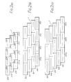
- Figure 2(a) illustrates a printhead 1 made up of separable stacks 20a, 20b, 20c of laterally overlapping like modules having three laterally offset layers, 22, 24, 26 and providing a print density of 2N where N is the density of ink channels in one module.
- the horizontal line drawn in each module represents a line of nozzles located so that the nozzles from different layers interleave one another when projected onto the print line.
- One segment of the print line is made up from drops printed from the right hand side of the top layer modules 22a-d of the corresponding stack 20a-d and the left hand side of the middle layer modules 24a-d.
- a second segment is made up from drops printed from the right hand side of the middle layer modules 24a-d of the stack and the left hand side of the bottom layer modules 26a-d.
- the third segment is made up of the right hand side of the bottom layer modules 26a-d of one stack and the left hand side of the top layer modules of the adjacent stack 20b-e.
- Figure 2(b) shows a corresponding arrangement of stacks 30a-d having four layers of laterally overlapping like modules 32, 34, 36 and 38 in each layer and providing a print density of 3N.
- Figure 2(c) shows corresponding stacks 40a-c having five layers of like modules per stack and achieving a print density of 4N.
- the extra layer provides an interval between the overlapping modules in each layer to butt the adjacent modules at the same time providing for the supply of ink to the ink channels and air or solvent flow to the housekeeping manifolds as hereinafter described.
- Replaceable stacks of like laterally offset modules combined in laterally overlapping stacks of modules of this arrangement provide a number of advantages.
- One advantage of overlapping modules is that the ink modules can be conveniently butted in each layer leaving a region between the ink channels of adjoining modules containing no ink channels.
- the nozzles for supplying the corresponding region in the print line are made up from the other layers of modules. Since the outermost channels in each are located inwardly from the sides of the module, the modules have a robust construction.
- the next benefit is that by forming a print bar out of a number of replaceable stacks, field servicing of a wide printbar is more readily accomplished than by replacing the entire printbar. Modules in each stack may also optionally be replaced.
- a simple alignment procedure can be used for assembling the modules together into stacks using physical guides (such as dowels or pre-cut grooves and location bars) or optical means (using a vernier system of readily observed optical fringes).
- the same alignment procedure can be used progressively to locate nozzles relative to the modules during nozzle manufacture, to assemble modules into a stack and to assemble the stacks into the printbar so that the nozzles and nozzle plates are automatically aligned by appropriately designed jigging in manufacture relative to a fixed datum in the printbar. In this way all the nozzles in the stack are correctly interleaved in alignment with the printbar.
- a particular advantage of having nozzles interleaved from different layers of the stack is that even if failure of a whole module occurs, the print line shows only a change in the print shade and the drawing or written page is substantially readable.
- modules and stacks are individually replaceable, housekeeping manifold supplies, electronic power and data are organised on a printbar basis.
- a further advantage is that the same design of the ink channels 16 having the same density N and chip drive voltage can be incorporated into printbars having a multiple density of 2N, 3N and 4N etc., providing for a range of print quality from the same modular parts.
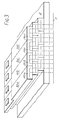
- Figure 3 shows an isometric perspective view of a three layer stack, in which the relative locations of the overlapping modules 10, stacks 20 and printbar 2 can be visualised. Segments of the print line 3 are each made up of nozzles interleaved from two modules in any section. To better illustrate this the print line is shown below the module layers. It is of course in practice to be found on the web or sheet which moves across the face of the printhead.
- the modules assembled in printbars in Figure 2 at first appear to be unconstrained in the number of nozzles per module and hence module size. Obviously once the resolution of nozzles N/mm in each module and the number of rows of nozzles r which are interleaved to form any particular section of the print line is decided, then if the number of layers of modules in a stack is (r + 1), the print line density is constrained to the integral multiple rN dots/mm.
- the number of ink channels energised by one chip is usually a binary number, for example 32 (5 bit) 64 (6 bit) or 128 (7 bit) etc: in addition one module may carry more than one chip.
- pitch interval of the stacks is found to be constrained once other choices are made to a limited number of preferred values from which printbars can be assembled.
- a particular feature of the stack construction is that the supplies of ink, the housekeeping manifold fluids and electronic power and data are organised on a printbar basis but are distributed through each stack individually. Accordingly the modules in each stack are designed to feed the supplies from one module to another vertically through the stack.
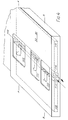
- FIG. 4 shows the printbar 2 on which is mounted a stack 30 having modules 32, 34, 36, 38 each made with two rows of nozzles 19 which communicate with ejector channels contained in the spaces 116.
- the modules are placed in four overlapping layers as previously illustrated in Figure 2(b).
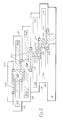
- the ink supply system which feeds make up inks vertically through each stack to replenish ink ejected from the print modules is shown in Figure 5 in the upper two modules 32 and 34, which are sectioned on AA in Figure 4 in the rear of each module.
- the modules are constructed as shown for modules 32 and 34 with ink feed manifolds 102 and 104 which are cut laterally across each module in opposite directions and are shown by the cross-hatching filled with ink.
- These manifolds connect with the ink channels 116 in Figure 4 (16 in Figure 1), so that suction is created in the manifolds when drops are ejected by actuation of the ink channels.
- the modules are cut away with apertures 105 and 107 on their upper and lower faces. These are offset so that corresponding apertures are in alignment when the modules are assembled as an overlapping stack and are sealed by means of an O-ring 109 (or similar means) inserted round the periphery of the apertures.
- the apertures 105, 107 are also connected by a riser 108.
- a cover 110 is employed to seal the riser at the top of the stack.
- the air flows which are fed to and from the housekeeping manifold are ducted through feed-throughs in each stack as illustrated in Figure 5 by the lower two modules 36 and 38. These are sectioned on BB in Figure 4 at the forward end of each module.
- the flow supplied to or from one portion of the housekeeping manifold is delivered through the bore 114 and the flow supplied to or from the other portion of the housekeeping manifold is delivered via bore 112.
- the bores 112 and 114 both exit the front face of the modules 32--38 and penetrate a substantial distance back through the modules between the space occupied by the ink channels 116.
- the bore 112 is connected to apertures on the upper and lower faces of each module of which aperture 115 is seen in Figure 4 whilst aperture 117 is shown in Figure 5.
- the apertures 115 and 117 are assembled in an overlapping stack.
- the apertures are sealed by means of O-rings.
- the bore 114 is similarly connected to apertures 115′ on the upper faces of the modules immediately behind and separate from the former apertures 115.
- Apertures (not shown) offset with respect to apertures 115′ are provided on the lower faces of the modules so that the modules can be similarly assembled and sealed.
- the stack assembly formed in this way enables a flow of ducted air to be delivered to or ducted from the modules in each stack by pressure and suction on the corresponding ducts in the printbar.
- both ink and ducted air flows can be fed from the printbar to modules stacked in laterally overlapping form of assembly for the continuous operation of the modules. If the modules provided a single group of ejectors rather than two groups, the ink supply duct would extend through the stacks rearwardly of the ink channels 116 where it would be connected to those channels, for example, by way of a manifold.
- Figure 6 shows an exploded view of the module 10 with two groups of closely spaced ink channels 16 placed on each side of the module in the majority of its width.
- Ducts for supplying air flows to or from the housekeeping manifold are labelled 112 and 114.
- a nozzle plate 17 Separated from the module is a nozzle plate 17 having two continuous rows 19 of ink ejector nozzles which selectively eject drops through the nozzles 18.
- the nozzle plates are made with apertures opposite the ducts 112 and 114. Displaced again from the nozzle plate 17 is the housekeeping manifold 50.
- the housekeeping manifold also has a trench 53 cut right through in the location opposite each row of nozzles 18 so that ejected drops (see Figure 8a) are shot through the trench 53.
- the module assembly is made by bonding these parts together as illustrated in Figure 7 and 8.
- the nozzle plate 17 is first bonded to the module 10, and the housekeeping manifold is next bonded to the nozzle plate. Air ducted from the bore 114 of the duct feed-throughs consequently enters the lower section 501 of the housekeeping manifold, where it spreads with uniform velocity by reason of the tapered section and exhausts through the row of apertures 55 in the trench wall into the trench.
- Suction from the printbar through bore 112 similarly exhausts air from the other side of the trench 53 by way of upper section 502 of the manifold: alternatively the air flow from bore 112 can be reversed and ducted out through the row of apertures 55 which join the trench 53 to the upper section 502 of the manifold to combine with and augment the flow already exhausting into the trench from the lower section of the manifold.
- the collection of dust on the nozzle plate is tolerated on travelling head drop-on-demand printers.
- the dust can be removed by high speed drop ejection or wiping.
- Such a routine is not acceptable on a wide bed drop-on-demand printer, where long term trouble free operation must be assured over the range of duty cycles experienced in the field.
- Dust is inherently part of the environment of a printer; it is carried in by electrostatic fields, convection currents and with paper movement and often originates from the paper. Operation of some jets causes dust to be pumped by convection into neighbouring jets. It is therefore evident that the provision of filtered dust free air past the printhead nozzles is essential for reliable operation.
- Filtered air flow to protect the nozzles from dust is conveniently provided by the housekeeping manifold 50. This is conveniently made practical by supplying the ducted air flow into the trench 53 in front of the nozzles as illustrated in Figure 8(a).
- housekeeping manifold 50 need not be confined to the module construction but can also be applied to a nozzle plate the full width of the printhead; or to a travelling printhead.
- the housekeeping air flow is needed during periods of operation of the printhead ( Figure 8(a)) but need not be employed when the printhead is dormant or waiting to be used, which is the status of a printer during the majority of its use.
- the trench 53 may therefore be covered by a sliding cover 57 ( Figure 8(b)) during dormant periods.
- the ducted air flow supplied to the housekeeping manifold causes scavenging air to flow in the trench and to remove solvent vapour evaporated from the ink meniscus.
- the ducted air can be modified to contain a proportion of solvent vapour (i.e. by controlled humidity).
- solvent vapour i.e. by controlled humidity.
- the partial pressure of the ink at operating temperature is low so that the solvent humidity necessary to avoid encrustation or formation of a film over the ink meniscus is low: but even high vapour pressure solvents (such as ethanol) can be held in a print ready status this way.
- the ducted air means that the conditions obtaining and therefore the degree of evaporation that has occurred at every nozzle is known. It is usually found that an ink will tolerate a known period such as 100 to 1000 seconds before ink drying becomes serious. Most inks have low vapour pressure additives that reduce the rate of evaporation of the low boiling point constituents. It is possible in that case to eject drops periodically from all under or unutilised nozzles, so that they are replenished with new ink as evaporation occurs, before the nozzle plug becomes too viscous, and inhibits printing.
- a further strategy is to make the printhead dormant for short periods (e.g. 15 seconds) at intervals, to circulate air with a higher solvent mass ratio so that any menisci which have a reduced solvent partial pressure (i.e. are dry) are restored. This is found to occur rapidly (e.g. in less than 15 seconds) and print ready status is restored. It may be preferred to close the sliding cover 57 over the trench 53 during this operation. However when there is no printing taking place, the tendency of ejected drops to set up flows which draw dust in is minimised. Thus solvent circulation can occur without closing the sliding cover with very little solvent loss. It will therefore be seen that the housekeeping manifold provides substantial opportunities to reduce and substantially eliminate the principal causes of drop-on-demand printhead unreliability and therefore to assure the levels of availability demanded of a wide array printhead.
- the housekeeping manifold further enables the printhead to be kept at a print ready status during dormant periods. This is obtained by closing the trench 53 with the sliding cover (or by another means) at the beginning of a dormant period and at the same time briefly circulating solvent rich air. It is sufficient to repeat this intermittently (i.e. every 1/2hr. to 1hr., depending on the temperature and other conditions) to maintain the menisci in a print ready status.
- the housekeeping manifold can be used to supply liquid solvent in the region of the printhead.
- the ducted air flows may be used in a different sequence at start up to remove the solvent from the housekeeping supply ducts and to reestablish a print ready status.
- connection is simplified by the realisation that every chip can be connected either in series or in parallel.
- One series of 8 parallel tracks can therefore be connected layer by layer through the stack to every chip. Electrical connection of a stack does not present serious problems even if double the number of parallel lines is required.
Landscapes
- Ink Jet (AREA)
- Particle Formation And Scattering Control In Inkjet Printers (AREA)
- Printers Or Recording Devices Using Electromagnetic And Radiation Means (AREA)
- Impact Printers (AREA)
- Printers Characterized By Their Purpose (AREA)
- Character Spaces And Line Spaces In Printers (AREA)
- Recording Measured Values (AREA)
Claims (11)
- Auf Abruf arbeitender Tintentropfen-Druckkopf zum selektiven Drucken von Tintentropfen in einer Druckzeile auf einem relativ zu dem Druckkopf bewegbaren Gewebe oder Blatt, der einen Körper (10), der mit einer Reihe von parallel ausgerichteten Tintenkanälen (16), jeweiligen Tintenausstoßöffnungen (18), die mit den Kanälen in Verbindung stehen und in einer Reihe an korrespondierenden Enden der Kanäle gebildet sind, ausgebildet ist, und Einrichtungen (12, 14, 16) aufweist, um Tintentropfen aus den Kanälen durch die Ausstoßöffnungen auszustoßen, dadurch gekennzeichnet, daß ein Graben bzw. Spalt (53), welcher sich parallel mit und vor den Reihen von Ausstoßöffnungen (18) erstreckt, über welchen Tintentropfen von den Öffnungen ausgestoßen werden, eine verteilende Leitungsverzweigung (50), die Bereiche (501, 502) auf gegenüberliegenden Seiten der Reihen von Ausstoßöffnungen aufweist, wobei die Leitungsverzweigung Öffnungen (55), welche die Leitungsverzweigung an gegenüberliegende Seiten des Grabens bzw. Spalts anschließt und Leitungseinrichtungen (112, 114) aufweist, um umgebende Fluide von dem Bereich der Reihen von Ausstoßöffnungen über die Bereiche aus der Leitungsverzweigung, den Öffnungen in der Leitungsverzweigung und dem Graben bzw. Spalt zuzuführen oder abzuführen.
- Auf Abruf arbeitender Druckkopf nach Anspruch 1, dadurch gekennzeichnet, daß der Körper (10) mit den Leitungseinrichtungen (112, 114) an einer Stelle benachbart zu bzw. angrenzend an die Reihe von Öffnungen (18) ausgebildet ist.
- Auf Abruf arbeitender Druckkopf nach Anspruch 1, dadurch gekennzeichnet, daß die Leitungseinrichtungen in der Mitte der Reihe von Ausstoßöffnungen angeordnet sind und sich die Bereiche (501, 502) der verteilenden Leitungsverzweigung jeweils in entgegengesetzten Richtungen zu den Enden der Reihen von Öffnungen verjüngen, so daß umgebendes Fluid, das dem Leitungsverzweigungsbereich zugeführt oder von diesem abgeführt wird, mit im wesentlichen gleichmäßiger Geschwindigkeit durch die Tropfenausstoßöffnungen strömt.
- Auf Abruf arbeitender Druckkopf nach einem der vorstehenden Ansprüche, dadurch gekennzeichnet, daß die verteilende Leitungsverzweigung eine leicht bewegbare Abdeckung (57) aufweist, welche in ihrer Vorwärtsstellung davon den Graben bzw. Spalt abdeckt und in ihrer zurückgezogenen Stellung davon den Graben freigibt, um es Tintentropfen, die von den Ausstoßöffnungen ausgestoßen worden sind, zu ermöglichen, auf eine Druckzeile auf dem Papier oder Gewebe geschossen bzw. gestoßen zu werden.
- Auf Abruf arbeitender Tintentropfen-Druckkopf nach einem der vorstehenden Ansprüche, dadurch gekennzeichnet, daß die umgebenden Fluide Luft enthalten, wobei die Luft mit Lösungsmitteldampf und flüssigem Lösungsmittel angefeuchtet ist.
- Auf Abruf arbeitender Druckkopf, gekennzeichnet durch Lagen bzw. Schichten (22, 24, 26, 32, 34, 36, 38, 42, 44, 46, 48, 49) aus gleichen Druckmodulen (10), von welchen benachbarte Lagen jeweils seitlich versetzt sind, wobei die Module jeweils aus einer Reihe von Tintentropfen-Ausstoßeinrichtungen ausgebildet sind, die zumindest eine Gruppe von linear gleichmäßig beabstandeten, parallel ausgerichteten Ausstoßeinrichtungen zur Verfügung stellen, wobei die Gruppen von Ausstoßeinrichtungen in jeder der Lagen bzw. Schichten der Reihe nach linear durch den gleichen Betrag beabstandet sind und in den Lagen bzw. Schichten korrespondierende Bereiche, in der Anzahl eins weniger als die Anzahl der Lagen bzw. Schichten, zur Verfügung stehen, und die zusammen in der Lage sind, Tintentropfen in einen bestimmten Bereich der Druckzeile abzuscheiden, wobei jedes Druckmodul mit einer verteilenden Leitungsverzweigung, einem Graben bzw. Spalt und Leitungseinrichtungen nach einem der Ansprüche 1 bis 5 versehen ist.
- Auf Abruf arbeitender Druckkopf nach Anspruch 6, dadurch gekennzeichnet, daß jedes Modul mit zwei beabstandeten Gruppen aus Tintenausstoßeinrichtung und mit Leitungseinrichtungen (112, 114) zum Zuführen umgebenden Fluids dazwischen ausgebildet ist, wobei die Zuführleitungseinrichtungen einen Durchgangsbereich, der sich durch das Modul, quer bzw. transversal zu der Modullage bzw. -schicht erstreckt und eine Leitung aufweisen, welche an den Durchgangsbereich angeschlossen ist und an dem Tropfenausstoßende des Moduls zwischen den Gruppen mündet, wobei die Anordnung derart ist, daß der Durchgangsbereich von korrespondierenden Modulen in der Modullage bzw. -schicht einen kontinuierlichen Fluidzufuhr- oder -abfuhrdurchgang durch die Modullage bzw. -schicht bildet.
- Auf Abruf arbeitender Druckkopf nach Anspruch 7, dadurch gekennzeichnet, daß die Leitungseinrichtungen zwei Durchgangsbereiche (115, 115¹) aufweisen, die sich jeweils durch das Modul quer bzw. transversal zu dem Modul und entsprechenden Leitungen erstrecken, welche an die Durchgangsbereiche der Leitungen (112, 114) anschließen, die an dem Tropfenausstoßende des Moduls zwischen den Gruppen münden.
- Auf Abruf arbeitender Druckkopf nach Anspruch 8, dadurch gekennzeichnet, daß die verteilende Leitungsverzweigung obere und untere Bereiche (502, 501) aufweist, die an jeweiligen gegenüberliegenden bzw. entgegengesetzten Enden der Reihe von Ausstoßöffnungen angeordnet sind und die Leitungen jeweils in die oberen und unteren Leitungsverzweigungsbereiche münden.
- Auf Abruf arbeitender Druckkopf nach einem der Ansprüche 6 bis 9, dadurch gekennzeichnet, daß Ausgleichstinten-Zuführeinrichtungen der Module eine Steigleitung (108) aufweisen, die sich durch korrespondierende Module von Modullagen bzw. -schichten erstrecken, welche in jedem Modul an die Tintenausstoßeinrichtungen angeschlossen ist.
- Auf Abruf arbeitender Druckkopf nach Anspruch 10, dadurch gekennzeichnet, daß die Steigleitung in jedem Modul an eine Leitungsverzweigungseinrichtung angeschlossen ist, welche wiederum an die Tintenausstoßeinrichtungen angeschlossen ist.
Priority Applications (1)
| Application Number | Priority Date | Filing Date | Title |
|---|---|---|---|
| AT89304098T ATE90620T1 (de) | 1988-04-29 | 1989-04-25 | Auf abruf arbeitender druckkopf. |
Applications Claiming Priority (2)
| Application Number | Priority Date | Filing Date | Title |
|---|---|---|---|
| GB888810241A GB8810241D0 (en) | 1988-04-29 | 1988-04-29 | Drop-on-demand printhead |
| GB8810241 | 1988-04-29 |
Publications (2)
| Publication Number | Publication Date |
|---|---|
| EP0340960A1 EP0340960A1 (de) | 1989-11-08 |
| EP0340960B1 true EP0340960B1 (de) | 1993-06-16 |
Family
ID=10636143
Family Applications (2)
| Application Number | Title | Priority Date | Filing Date |
|---|---|---|---|
| EP89304097A Expired - Lifetime EP0339926B1 (de) | 1988-04-29 | 1989-04-25 | Auf Abruf arbeitender Druckkopf |
| EP89304098A Expired - Lifetime EP0340960B1 (de) | 1988-04-29 | 1989-04-25 | Auf Abruf arbeitender Druckkopf |
Family Applications Before (1)
| Application Number | Title | Priority Date | Filing Date |
|---|---|---|---|
| EP89304097A Expired - Lifetime EP0339926B1 (de) | 1988-04-29 | 1989-04-25 | Auf Abruf arbeitender Druckkopf |
Country Status (8)
| Country | Link |
|---|---|
| US (2) | US4942409A (de) |
| EP (2) | EP0339926B1 (de) |
| JP (2) | JP2850133B2 (de) |
| AT (2) | ATE90619T1 (de) |
| CA (2) | CA1320385C (de) |
| DE (2) | DE68907118T2 (de) |
| ES (1) | ES2041413T3 (de) |
| GB (1) | GB8810241D0 (de) |
Families Citing this family (59)
| Publication number | Priority date | Publication date | Assignee | Title |
|---|---|---|---|---|
| GB8906379D0 (en) * | 1989-03-20 | 1989-05-04 | Am Int | Providing a surface with solvent-wettable and solvent-non wettable zones |
| NL8900760A (nl) * | 1989-03-28 | 1990-10-16 | Stork X Cel Bv | Mondstukconfiguratie voor een inktstraaldrukinrichting. |
| ES2073670T3 (es) * | 1990-02-02 | 1995-08-16 | Canon Kk | Aparato para la impresion por chorros de tinta y cabezal para la impresion por chorros de tinta. |
| GB9010289D0 (en) * | 1990-05-08 | 1990-06-27 | Xaar Ltd | Drop-on-demand printing apparatus and method of manufacture |
| AU657720B2 (en) * | 1991-01-30 | 1995-03-23 | Canon Kabushiki Kaisha | A bubblejet image reproducing apparatus |
| AU657931B2 (en) * | 1991-01-30 | 1995-03-30 | Canon Kabushiki Kaisha | An integrally formed bubblejet print device |
| US5245244A (en) * | 1991-03-19 | 1993-09-14 | Brother Kogyo Kabushiki Kaisha | Piezoelectric ink droplet ejecting device |
| US5160945A (en) * | 1991-05-10 | 1992-11-03 | Xerox Corporation | Pagewidth thermal ink jet printhead |
| US5410341A (en) * | 1991-05-28 | 1995-04-25 | Brother Kogyo Kabushiki Kaisha | Droplet jet device |
| US5302976A (en) * | 1991-05-30 | 1994-04-12 | Brother Kogyo Kabushiki Kaisha | Low-voltage actuatable ink droplet ejection device |
| JP2867740B2 (ja) * | 1991-05-31 | 1999-03-10 | ブラザー工業株式会社 | 液滴噴射装置 |
| JPH0577420A (ja) * | 1991-09-20 | 1993-03-30 | Brother Ind Ltd | 液滴噴射装置 |
| JPH05124186A (ja) * | 1991-11-06 | 1993-05-21 | Brother Ind Ltd | 液滴噴射装置 |
| JP3097298B2 (ja) * | 1992-04-17 | 2000-10-10 | ブラザー工業株式会社 | 液滴噴射装置およびその製造方法 |
| JPH05330085A (ja) * | 1992-05-29 | 1993-12-14 | Yoshida Kogyo Kk <Ykk> | インクジェットによる連続走行帯状物用プリンター |
| DE4225799A1 (de) * | 1992-07-31 | 1994-02-03 | Francotyp Postalia Gmbh | Tintenstrahldruckkopf und Verfahren zu seiner Herstellung |
| GB2280149A (en) * | 1993-06-23 | 1995-01-25 | Willett Int Ltd | Preventing nozzle clogging in ink-jet printers. |
| JP3423412B2 (ja) * | 1993-06-23 | 2003-07-07 | キヤノン株式会社 | インクジェット記録方法及び記録装置 |
| DE4336416A1 (de) * | 1993-10-19 | 1995-08-24 | Francotyp Postalia Gmbh | Face-Shooter-Tintenstrahldruckkopf und Verfahren zu seiner Herstellung |
| JPH0825635A (ja) * | 1994-07-21 | 1996-01-30 | Canon Inc | インクジェットプリント装置およびプリントヘッドユニット |
| US5812065A (en) | 1995-08-14 | 1998-09-22 | International Business Machines Corporation | Modulation of the resonant frequency of a circuit using an energy field |
| US7002475B2 (en) * | 1997-12-31 | 2006-02-21 | Intermec Ip Corp. | Combination radio frequency identification transponder (RFID tag) and magnetic electronic article surveillance (EAS) tag |
| AUPN623795A0 (en) * | 1995-10-30 | 1995-11-23 | Eastman Kodak Company | A modular lift print head |
| US5901425A (en) | 1996-08-27 | 1999-05-11 | Topaz Technologies Inc. | Inkjet print head apparatus |
| US5923348A (en) * | 1997-02-26 | 1999-07-13 | Lexmark International, Inc. | Method of printing using a printhead having multiple rows of ink emitting orifices |
| US6238044B1 (en) * | 2000-06-30 | 2001-05-29 | Silverbrook Research Pty Ltd | Print cartridge |
| WO1999011461A1 (en) * | 1997-08-29 | 1999-03-11 | Topaz Technologies, Inc. | Integrated head assembly for an ink jet printer |
| US6350013B1 (en) * | 1997-10-28 | 2002-02-26 | Hewlett-Packard Company | Carrier positioning for wide-array inkjet printhead assembly |
| US6065825A (en) * | 1997-11-13 | 2000-05-23 | Eastman Kodak Company | Printer having mechanically-assisted ink droplet separation and method of using same |
| EP0964783A1 (de) * | 1997-11-19 | 1999-12-22 | KUEHNLE, Manfred R. | Markiergerät mit mikrokanälen |
| US6575558B1 (en) | 1999-03-26 | 2003-06-10 | Spectra, Inc. | Single-pass inkjet printing |
| US6592204B1 (en) | 1999-03-26 | 2003-07-15 | Spectra, Inc. | Single-pass inkjet printing |
| US6257699B1 (en) | 1999-10-13 | 2001-07-10 | Xerox Corporation | Modular carriage assembly for use with high-speed, high-performance, printing device |
| SE516696C2 (sv) | 1999-12-23 | 2002-02-12 | Perstorp Flooring Ab | Förfarande för framställning av ytelement vilka innefattar ett övre dekorativt skikt samt ytelement framställda enlit förfarandet |
| US6997538B1 (en) * | 2000-05-15 | 2006-02-14 | Hewlett-Packard Development Company, L.P. | Inkjet printing with air current disruption |
| EP1284860B1 (de) | 2000-05-15 | 2010-04-07 | Hewlett-Packard Company | Tintenstrahldrucken mit luftstromsystem |
| US6412908B2 (en) * | 2000-05-23 | 2002-07-02 | Silverbrook Research Pty Ltd | Inkjet collimator |
| US6612240B1 (en) * | 2000-09-15 | 2003-09-02 | Silverbrook Research Pty Ltd | Drying of an image on print media in a modular commercial printer |
| AU2004203499B2 (en) * | 2001-03-27 | 2005-07-21 | Memjet Technology Limited | Ink channel extrusion for a printer assembly |
| AUPR399001A0 (en) * | 2001-03-27 | 2001-04-26 | Silverbrook Research Pty. Ltd. | An apparatus and method(ART104) |
| US6428141B1 (en) * | 2001-04-23 | 2002-08-06 | Hewlett-Packard Company | Reference datums for inkjet printhead assembly |
| US6588889B2 (en) * | 2001-07-16 | 2003-07-08 | Eastman Kodak Company | Continuous ink-jet printing apparatus with pre-conditioned air flow |
| JP4023331B2 (ja) * | 2002-06-03 | 2007-12-19 | ソニー株式会社 | 液体吐出装置及び液体吐出方法 |
| JP2005047207A (ja) * | 2003-07-31 | 2005-02-24 | Shinko Electric Ind Co Ltd | インクジェット方式の印刷機 |
| JP2005125195A (ja) * | 2003-10-22 | 2005-05-19 | Seiko Epson Corp | 吐出装置、塗布方法、カラーフィルタ基板の製造方法、エレクトロルミネッセンス表示装置の製造方法、プラズマ表示装置の製造方法、および配線製造方法 |
| US7281330B2 (en) * | 2004-05-27 | 2007-10-16 | Silverbrook Research Pty Ltd | Method of manufacturing left-handed and right-handed printhead modules |
| JP2008030317A (ja) * | 2006-07-28 | 2008-02-14 | Toshiba Tec Corp | インクジェットヘッド |
| GB2447919B (en) * | 2007-03-27 | 2012-04-04 | Linx Printing Tech | Ink jet printing |
| US20090091605A1 (en) * | 2007-10-09 | 2009-04-09 | Jinquan Xu | Printer including oscillatory fluid flow device |
| JP2010018019A (ja) | 2007-11-29 | 2010-01-28 | Seiko Epson Corp | 液体吐出装置 |
| JP5084478B2 (ja) * | 2007-12-07 | 2012-11-28 | キヤノン株式会社 | インクジェット記録ヘッドおよびインクジェット記録装置 |
| EP2241442B1 (de) * | 2008-01-28 | 2011-10-26 | Hitachi Industrial Equipment Systems Co., Ltd. | Tintenstrahlaufzeichnungsvorrichtung |
| US8167404B2 (en) | 2009-07-17 | 2012-05-01 | Xerox Corporation | Staggered head stitch shifts in a continuous feed direct marking printer |
| US8292398B2 (en) | 2010-05-14 | 2012-10-23 | Xerox Corporation | Method and system for printhead alignment to compensate for dimensional changes in a media web in an inkjet printer |
| US8517502B2 (en) | 2011-02-14 | 2013-08-27 | Xerox Corporation | Method and system for printhead alignment to reduce or eliminate banding artifacts for interlaced printheads |
| EP2914434B1 (de) | 2012-10-30 | 2017-06-14 | Hewlett-Packard Development Company, L.P. | Tintenaerosol-filterung |
| GB2522563B (en) * | 2013-11-26 | 2015-11-04 | Xaar Technology Ltd | Droplet deposition apparatus and method for manufacturing the same |
| US9434155B1 (en) | 2015-08-31 | 2016-09-06 | Xerox Corporation | Method and system for printhead alignment based on print medium width |
| PT3344459T (pt) * | 2015-09-02 | 2019-12-11 | Tonejet Ltd | Método de funcionamento de uma cabeça de impressão de jacto de tinta |
Family Cites Families (26)
| Publication number | Priority date | Publication date | Assignee | Title |
|---|---|---|---|---|
| US3560641A (en) * | 1968-10-18 | 1971-02-02 | Mead Corp | Image construction system using multiple arrays of drop generators |
| US3946398A (en) * | 1970-06-29 | 1976-03-23 | Silonics, Inc. | Method and apparatus for recording with writing fluids and drop projection means therefor |
| US4106032A (en) * | 1974-09-26 | 1978-08-08 | Matsushita Electric Industrial Co., Limited | Apparatus for applying liquid droplets to a surface by using a high speed laminar air flow to accelerate the same |
| US4002230A (en) * | 1975-07-09 | 1977-01-11 | Houston Engineering Research Corporation | Print head apparatus |
| US4194210A (en) * | 1976-03-29 | 1980-03-18 | International Business Machines Corporation | Multi-nozzle ink jet print head apparatus |
| US4063254A (en) * | 1976-06-28 | 1977-12-13 | International Business Machines Corporation | Multiple array printer |
| JPS54123950A (en) * | 1978-03-17 | 1979-09-26 | Matsushita Electric Ind Co Ltd | Ink jet recorder |
| GB2022018B (en) * | 1978-05-30 | 1982-05-06 | Tektronix Inc | Thermal transfer colour printer |
| US4232324A (en) * | 1978-06-05 | 1980-11-04 | International Business Machines Corporation | Apparatus for arranging scanning heads for interlacing |
| US4317124A (en) * | 1979-02-14 | 1982-02-23 | Canon Kabushiki Kaisha | Ink jet recording apparatus |
| US4520373A (en) * | 1979-04-02 | 1985-05-28 | Canon Kabushiki Kaisha | Droplet generating method and apparatus therefor |
| JPS5764563A (en) * | 1980-10-07 | 1982-04-19 | Fuji Xerox Co Ltd | Ink particle jet apparatus of multi-nozzle ink jet printer |
| JPS57113075A (en) * | 1980-12-30 | 1982-07-14 | Fujitsu Ltd | Ink jet head |
| JPS5862057A (ja) * | 1981-10-08 | 1983-04-13 | Canon Inc | インクジェット装置用回復装置及びそれを備えたインクジェット装置 |
| JPS58114963A (ja) * | 1981-12-28 | 1983-07-08 | Matsushita Electric Ind Co Ltd | インクジエツトヘツド |
| US4510509A (en) * | 1982-03-09 | 1985-04-09 | Ricoh Company, Ltd. | Ink ejection head |
| DE3238353A1 (de) * | 1982-10-15 | 1984-04-19 | Max Planck Gesellschaft zur Förderung der Wissenschaften e.V., 3400 Göttingen | Verfahren zur simultanen quantitativen bestimmung der blutzellen und reagenz hierfuer |
| JPS6046258A (ja) * | 1983-08-24 | 1985-03-13 | Sanyo Electric Co Ltd | インクジエツトプリンタ |
| JPS60101054A (ja) * | 1983-11-08 | 1985-06-05 | Canon Inc | 液体噴射装置 |
| US4540997A (en) * | 1984-03-26 | 1985-09-10 | Tektronix, Inc. | Method and apparatus for avoiding the drying of ink in the ink jets of ink jet printers |
| JPS60203466A (ja) * | 1984-03-29 | 1985-10-15 | Toshiba Corp | サ−マルヘツド |
| JPS61242848A (ja) * | 1985-04-22 | 1986-10-29 | Ricoh Co Ltd | インクジエツト記録用シヤツタ |
| US4612554A (en) * | 1985-07-29 | 1986-09-16 | Xerox Corporation | High density thermal ink jet printhead |
| JPS6322661A (ja) * | 1986-07-15 | 1988-01-30 | Soatetsuku Kk | 印字ヘツド装置 |
| US4727378A (en) * | 1986-07-11 | 1988-02-23 | Tektronix, Inc. | Method and apparatus for purging an ink jet head |
| GB8622196D0 (en) * | 1986-09-15 | 1986-10-22 | Domino Printing Sciences Plc | Ink jet marking apparatus |
-
1988
- 1988-04-29 GB GB888810241A patent/GB8810241D0/en active Pending
-
1989
- 1989-04-25 AT AT89304097T patent/ATE90619T1/de not_active IP Right Cessation
- 1989-04-25 EP EP89304097A patent/EP0339926B1/de not_active Expired - Lifetime
- 1989-04-25 DE DE89304097T patent/DE68907118T2/de not_active Expired - Lifetime
- 1989-04-25 AT AT89304098T patent/ATE90620T1/de not_active IP Right Cessation
- 1989-04-25 EP EP89304098A patent/EP0340960B1/de not_active Expired - Lifetime
- 1989-04-25 ES ES198989304098T patent/ES2041413T3/es not_active Expired - Lifetime
- 1989-04-25 DE DE89304098T patent/DE68907122T2/de not_active Expired - Lifetime
- 1989-04-28 US US07/345,610 patent/US4942409A/en not_active Expired - Lifetime
- 1989-04-28 CA CA000598265A patent/CA1320385C/en not_active Expired - Lifetime
- 1989-04-28 US US07/345,600 patent/US4940996A/en not_active Expired - Lifetime
- 1989-04-28 JP JP1107966A patent/JP2850133B2/ja not_active Expired - Fee Related
- 1989-04-28 CA CA000598266A patent/CA1320386C/en not_active Expired - Lifetime
- 1989-04-28 JP JP1107965A patent/JPH0211330A/ja active Pending
Also Published As
| Publication number | Publication date |
|---|---|
| US4942409A (en) | 1990-07-17 |
| DE68907122D1 (de) | 1993-07-22 |
| US4940996A (en) | 1990-07-10 |
| JPH0211330A (ja) | 1990-01-16 |
| DE68907122T2 (de) | 1993-12-09 |
| EP0339926B1 (de) | 1993-06-16 |
| ATE90619T1 (de) | 1993-07-15 |
| EP0339926A1 (de) | 1989-11-02 |
| CA1320386C (en) | 1993-07-20 |
| EP0340960A1 (de) | 1989-11-08 |
| JP2850133B2 (ja) | 1999-01-27 |
| DE68907118D1 (de) | 1993-07-22 |
| GB8810241D0 (en) | 1988-06-02 |
| JPH0211333A (ja) | 1990-01-16 |
| ES2041413T3 (es) | 1993-11-16 |
| DE68907118T2 (de) | 1993-12-09 |
| CA1320385C (en) | 1993-07-20 |
| ATE90620T1 (de) | 1993-07-15 |
Similar Documents
| Publication | Publication Date | Title |
|---|---|---|
| EP0340960B1 (de) | Auf Abruf arbeitender Druckkopf | |
| US6705704B2 (en) | Droplet deposition method and apparatus | |
| EP1790482B1 (de) | Flüssigkeitsausstosskopf, Flüssigkeitsversorgungsvorrichtung, Flüssigkeitsausstossvorrichtung und Flüssigkeitsversorgungsverfahren | |
| US6447088B2 (en) | Ink-jet head, an ink-jet-head cartridge, an ink-jet apparatus and an ink-jet recording method used in gradation recording | |
| US8662643B2 (en) | Liquid jet head and liquid jet apparatus | |
| US8123319B2 (en) | High speed high resolution fluid ejection | |
| US6652068B2 (en) | Compact printhead and method of delivering ink to the printhead | |
| US6530645B2 (en) | Print masks for high speed ink jet printing | |
| US6662435B1 (en) | Method of manufacturing an ink jet print head | |
| JPH03234651A (ja) | インクジェット記録装置 | |
| KR20090014034A (ko) | 잉크젯 화상형성장치 | |
| EP1022148B1 (de) | Drucker mit Medientransport koordiniert mit der Primitivengrösse | |
| US6474776B1 (en) | Ink jet cartridge with two jet plates | |
| JP2003080711A (ja) | プリンタヘッドチップ及びプリンタヘッド | |
| JPH06106731A (ja) | インクジェット記録手段およびインクジェット記録装置 | |
| EP1245000B1 (de) | Maskenmuster für das hochgeschwindigkeitstintenstrahldrucken | |
| JPH05338206A (ja) | インクジェット記録装置 | |
| US20260070331A1 (en) | Liquid ejection head and liquid ejection apparatus | |
| KR100510814B1 (ko) | 잉크 제트 기록 장치, 잉크 제트 기록 헤드 및 잉크 제트기록 방법 | |
| JPH05124192A (ja) | 記録装置 | |
| KR20170083500A (ko) | 기록 소자 기판 및 액체 토출 헤드 | |
| CN121671178A (zh) | 液体喷射头和液体喷射设备 | |
| Collins et al. | Maze | |
| CN121625630A (zh) | 液体喷射头和液体喷射设备 | |
| JPH03234634A (ja) | インクジェット記録ヘッドおよび該記録ヘッドを搭載したインクジェット記録装置 |
Legal Events
| Date | Code | Title | Description |
|---|---|---|---|
| PUAI | Public reference made under article 153(3) epc to a published international application that has entered the european phase |
Free format text: ORIGINAL CODE: 0009012 |
|
| AK | Designated contracting states |
Kind code of ref document: A1 Designated state(s): AT CH DE ES FR GB GR IT LI NL SE |
|
| 17P | Request for examination filed |
Effective date: 19900125 |
|
| RAP1 | Party data changed (applicant data changed or rights of an application transferred) |
Owner name: XAAR LIMITED |
|
| 17Q | First examination report despatched |
Effective date: 19911002 |
|
| GRAA | (expected) grant |
Free format text: ORIGINAL CODE: 0009210 |
|
| AK | Designated contracting states |
Kind code of ref document: B1 Designated state(s): AT CH DE ES FR GB GR IT LI NL SE |
|
| PG25 | Lapsed in a contracting state [announced via postgrant information from national office to epo] |
Ref country code: GR Free format text: LAPSE BECAUSE OF FAILURE TO SUBMIT A TRANSLATION OF THE DESCRIPTION OR TO PAY THE FEE WITHIN THE PRESCRIBED TIME-LIMIT Effective date: 19930616 |
|
| REF | Corresponds to: |
Ref document number: 90620 Country of ref document: AT Date of ref document: 19930715 Kind code of ref document: T |
|
| ITF | It: translation for a ep patent filed | ||
| REF | Corresponds to: |
Ref document number: 68907122 Country of ref document: DE Date of ref document: 19930722 |
|
| ET | Fr: translation filed | ||
| REG | Reference to a national code |
Ref country code: ES Ref legal event code: FG2A Ref document number: 2041413 Country of ref document: ES Kind code of ref document: T3 |
|
| PLBE | No opposition filed within time limit |
Free format text: ORIGINAL CODE: 0009261 |
|
| STAA | Information on the status of an ep patent application or granted ep patent |
Free format text: STATUS: NO OPPOSITION FILED WITHIN TIME LIMIT |
|
| 26N | No opposition filed | ||
| EAL | Se: european patent in force in sweden |
Ref document number: 89304098.0 |
|
| PGFP | Annual fee paid to national office [announced via postgrant information from national office to epo] |
Ref country code: AT Payment date: 19960411 Year of fee payment: 8 |
|
| PGFP | Annual fee paid to national office [announced via postgrant information from national office to epo] |
Ref country code: ES Payment date: 19960429 Year of fee payment: 8 |
|
| PG25 | Lapsed in a contracting state [announced via postgrant information from national office to epo] |
Ref country code: AT Effective date: 19970425 |
|
| PG25 | Lapsed in a contracting state [announced via postgrant information from national office to epo] |
Ref country code: ES Free format text: LAPSE BECAUSE OF NON-PAYMENT OF DUE FEES Effective date: 19970426 |
|
| REG | Reference to a national code |
Ref country code: ES Ref legal event code: FD2A Effective date: 19990301 |
|
| REG | Reference to a national code |
Ref country code: GB Ref legal event code: IF02 |
|
| PGFP | Annual fee paid to national office [announced via postgrant information from national office to epo] |
Ref country code: SE Payment date: 20030404 Year of fee payment: 15 |
|
| PGFP | Annual fee paid to national office [announced via postgrant information from national office to epo] |
Ref country code: CH Payment date: 20030502 Year of fee payment: 15 |
|
| PG25 | Lapsed in a contracting state [announced via postgrant information from national office to epo] |
Ref country code: SE Free format text: LAPSE BECAUSE OF NON-PAYMENT OF DUE FEES Effective date: 20040426 |
|
| PG25 | Lapsed in a contracting state [announced via postgrant information from national office to epo] |
Ref country code: CH Free format text: LAPSE BECAUSE OF NON-PAYMENT OF DUE FEES Effective date: 20040430 Ref country code: LI Free format text: LAPSE BECAUSE OF NON-PAYMENT OF DUE FEES Effective date: 20040430 |
|
| EUG | Se: european patent has lapsed | ||
| REG | Reference to a national code |
Ref country code: CH Ref legal event code: PL |
|
| PGFP | Annual fee paid to national office [announced via postgrant information from national office to epo] |
Ref country code: FR Payment date: 20080312 Year of fee payment: 20 Ref country code: DE Payment date: 20080502 Year of fee payment: 20 |
|
| PGFP | Annual fee paid to national office [announced via postgrant information from national office to epo] |
Ref country code: IT Payment date: 20080428 Year of fee payment: 20 |
|
| PGFP | Annual fee paid to national office [announced via postgrant information from national office to epo] |
Ref country code: NL Payment date: 20080303 Year of fee payment: 20 |
|
| PGFP | Annual fee paid to national office [announced via postgrant information from national office to epo] |
Ref country code: GB Payment date: 20080430 Year of fee payment: 20 |
|
| REG | Reference to a national code |
Ref country code: GB Ref legal event code: PE20 Expiry date: 20090424 |
|
| PG25 | Lapsed in a contracting state [announced via postgrant information from national office to epo] |
Ref country code: NL Free format text: LAPSE BECAUSE OF EXPIRATION OF PROTECTION Effective date: 20090425 |
|
| NLV7 | Nl: ceased due to reaching the maximum lifetime of a patent |
Effective date: 20090425 |
|
| PG25 | Lapsed in a contracting state [announced via postgrant information from national office to epo] |
Ref country code: GB Free format text: LAPSE BECAUSE OF EXPIRATION OF PROTECTION Effective date: 20090424 |