EP0341143A1 - Gerät und Verfahren zur Tomographie mit erhöhter Aufnahmgeschwindigkeit - Google Patents
Gerät und Verfahren zur Tomographie mit erhöhter Aufnahmgeschwindigkeit Download PDFInfo
- Publication number
- EP0341143A1 EP0341143A1 EP89401219A EP89401219A EP0341143A1 EP 0341143 A1 EP0341143 A1 EP 0341143A1 EP 89401219 A EP89401219 A EP 89401219A EP 89401219 A EP89401219 A EP 89401219A EP 0341143 A1 EP0341143 A1 EP 0341143A1
- Authority
- EP
- European Patent Office
- Prior art keywords
- multidetector
- ray tube
- assembly
- translation
- rotation
- Prior art date
- Legal status (The legal status is an assumption and is not a legal conclusion. Google has not performed a legal analysis and makes no representation as to the accuracy of the status listed.)
- Withdrawn
Links
- 238000003325 tomography Methods 0.000 title claims description 13
- 238000000034 method Methods 0.000 title claims description 11
- 238000013519 translation Methods 0.000 claims abstract description 39
- 238000012545 processing Methods 0.000 claims description 7
- 238000012546 transfer Methods 0.000 claims description 7
- 230000008569 process Effects 0.000 claims description 6
- 230000014616 translation Effects 0.000 abstract description 28
- 230000008901 benefit Effects 0.000 abstract description 3
- 230000006872 improvement Effects 0.000 abstract description 3
- 238000002560 therapeutic procedure Methods 0.000 abstract description 2
- 238000012544 monitoring process Methods 0.000 abstract 1
- 230000005855 radiation Effects 0.000 description 13
- 238000006073 displacement reaction Methods 0.000 description 9
- 238000004422 calculation algorithm Methods 0.000 description 7
- 238000001959 radiotherapy Methods 0.000 description 7
- 230000001133 acceleration Effects 0.000 description 5
- 230000010354 integration Effects 0.000 description 5
- 238000005070 sampling Methods 0.000 description 5
- 238000010521 absorption reaction Methods 0.000 description 4
- 210000000056 organ Anatomy 0.000 description 4
- 238000001514 detection method Methods 0.000 description 3
- 230000004048 modification Effects 0.000 description 3
- 238000012986 modification Methods 0.000 description 3
- 230000035945 sensitivity Effects 0.000 description 3
- 230000002457 bidirectional effect Effects 0.000 description 2
- 230000000052 comparative effect Effects 0.000 description 2
- 230000007547 defect Effects 0.000 description 2
- 238000010586 diagram Methods 0.000 description 2
- 230000000694 effects Effects 0.000 description 2
- 230000006641 stabilisation Effects 0.000 description 2
- 238000011105 stabilization Methods 0.000 description 2
- 210000003484 anatomy Anatomy 0.000 description 1
- 230000000295 complement effect Effects 0.000 description 1
- 230000001419 dependent effect Effects 0.000 description 1
- 210000003141 lower extremity Anatomy 0.000 description 1
- 238000005259 measurement Methods 0.000 description 1
- 230000007246 mechanism Effects 0.000 description 1
- 239000002184 metal Substances 0.000 description 1
- 230000008520 organization Effects 0.000 description 1
- 238000004088 simulation Methods 0.000 description 1
- 238000010408 sweeping Methods 0.000 description 1
- 238000011144 upstream manufacturing Methods 0.000 description 1
- 229910052724 xenon Inorganic materials 0.000 description 1
- FHNFHKCVQCLJFQ-UHFFFAOYSA-N xenon atom Chemical compound [Xe] FHNFHKCVQCLJFQ-UHFFFAOYSA-N 0.000 description 1
Images


Classifications
-
- A—HUMAN NECESSITIES
- A61—MEDICAL OR VETERINARY SCIENCE; HYGIENE
- A61B—DIAGNOSIS; SURGERY; IDENTIFICATION
- A61B6/00—Apparatus or devices for radiation diagnosis; Apparatus or devices for radiation diagnosis combined with radiation therapy equipment
- A61B6/02—Arrangements for diagnosis sequentially in different planes; Stereoscopic radiation diagnosis
- A61B6/03—Computed tomography [CT]
- A61B6/032—Transmission computed tomography [CT]
Definitions
- the subject of the present invention is a device and a method of tomography at a high rate of acquisition, usable in particular in the medical field.
- the essential constraint consists in allowing the practitioner to access any organ of a patient at any time, even during the acquisition phase of the tomographies.
- the total duration of acquisition of the information which makes it possible to reconstruct this image depends on the speed of rotation of the X-ray tube-multidetector assembly, on the power of the X-ray tube and on the sensitivity of the detector.
- the more powerful an X-ray tube the more it will emit X-rays of a given hardness (and not harder X-rays)
- the more sensitive the detector the better its quantum efficiency, the more the acquisition speed can also be increased.
- the speed of rotation of the assembly is a determining factor in the quality of the reconstructed image. Indeed, the slower the speed, the more it is possible to leave the multidetectors under a long influence of the X-ray tube at each view, and the more the information delivered by each of the cells of this multidetector will be precise and representative. In contrast, the faster you go, the more the image degrades in terms of its precision or resolution.
- the reconstructed image tomography machines currently available are mainly so-called third generation machines.
- the X-ray tube-multidetector assembly although rotating, is connected by cables to the circuits supply and reception of the machine.
- An acquisition then requires the acceleration at start-up of the X-ray multidetector tube assembly, the speed stabilization of this assembly, the actual acquisition of information at a stabilized speed, and the slowing down and then stopping of the together (before tearing off the cable connections). All this rotational movement requires the assembly to perform approximately two turns on itself. For another acquisition, for the image of a section adjacent to a previously acquired section, this set of operations is repeated by rotating the machine in the other direction and so on.
- the duration of the acquisition in practice is not linked only to the choices mentioned above of image quality, but is especially linked to this type of start-up.
- the actual duration of acquisition varies between half a second for images whose required precision must be low, up to ten seconds for finely resolved images.
- the acquisition of information relating to a cut, taking into account acceleration and deceleration is of the order of ten seconds.
- the most well-known multidetectors are gas multidetectors comprising a set of cells filled with gas (generally Xenon). Each cell of the multidetector has two metal plates, electrically polarized at opposite voltages from one another. Under the effect of X-rays passing through the object, this gas ionizes and allows the passage of a leakage current between the two polarized plates at opposite high voltages. Measuring these leakage currents makes it possible to detect the necessary information to reconstruct the image.
- a multidetector therefore comprises a multitude of cells of the same type, aligned one behind the other in a row, the main direction of which is contained in the section plane of the X-ray tube-multidetector assembly.
- Such cells have a width, measured perpendicular to this cutting plane, of the order of 1.5 cm.
- a collimator is used whose purpose is to reduce the omnidirectional radiation from the tube to radiation in a flat fan-shaped beam, illuminating the entire detector, and whose width corresponds to the resolution step in thickness of the section to be reconstructed.
- this thickness can vary, from one machine to another, from 1 millimeter to 10 millimeters. When this thickness is equal to 10 millimeters, the flow of X-rays on the multidetector can more quickly reach a sensitive level, even for the most opaque regions of the object, so that such images which are the least good in resolution are however, the images acquired most quickly.
- the tube-detector assembly thus described taking into account the number of turns to be performed at each acquisition, must be contained in a fixed circular casing preventing operators working on this machine from being cut down.
- the acquisition of the different sections is made by relative displacement of this cover relative to an examination bed on which the object, the patient in the medical field is placed.
- the rollover is fixed to the ground, the bed moves in longitudinal translation in the machine.
- Such a circular cover does not allow a practitioner to have access at all times to all the organs of a patient. For example, if this patient undergoes an examination in the region of the heart, his head is on one side of the machine while his lower trunk and lower limbs are placed on the other side. This drawback is particularly troublesome if the tomograph is used in a device called "radiotherapy simulator".
- the purpose of such a device is to provide information on the internal and external anatomy of a patient to determine in advance the characteristics of the beams which will be used when this patient is subsequently placed on a radiotherapy device, such so that the radiation from the radiotherapy delivers the desired dose to the regions to be treated and the lowest possible dose to the other regions of this patient.
- the patient For the examination on the radiotherapy simulator the patient must be placed in the exact position he will have on the radiotherapy device. These positions are coded to give maximum efficiency to the treatment. They are often incompatible with the geometry of conventional tomography devices, especially since the operator must help the patient to take these positions. On the other hand, during the examination on the simulator, the operator must draw marks on the patient's skin which will allow the placement of therapy beams. These considerations require that the patient's vicinity is easily accessible during the examination on the simulator.
- the orders of comparative magnitudes are as follows: in the state of the art, 250 images comprising 1000 views each and during each 4 seconds, including the translation between images, led to a total acquisition time of 1000 seconds. With the technique of the invention, one will proceed in correspondence to 1000 translations each followed by a rotational movement of a pitch of the X-ray tube-multidetector assembly. It should be noted that these rotational step-by-step movements are of very small amplitude: they can therefore be very rapid. Indeed they are around 18 minutes of angle (at a degree of angle depending on the quality of the examination). Their rapid execution cannot pose any risk to operators close to the machine.
- the solution according to the invention has the advantage that the accelerations and decelerations of the assembly being relatively shorter, the relative duration of use of the multidetector for detection purposes may be longer.
- the sensitivity of the machine is increased. For example, if the scanning time longitudinal is of the order of 0.75 seconds for 25 centimeters, the duration of irradiation of the multidetector, relative to a slice of thickness 1 millimeter, is of the order of 3 milliseconds (0.750 / 250). In comparison with third generation machines, either this duration of use is shorter so that the total duration of acquisition is the same, or this intrinsic duration of use is the same, but the total duration of acquisition is then longer.
- the multidetector is of the multirange type.
- This multidetector comprises a two-dimensional network of detector cells. In this case the treatment is of discrete type.
- the electrical charges representative of the information of the cells of one of the rows of the multidirectional multidetector are transferred into adjacent cells of an adjacent row, in a direction opposite to the movement of the translation.
- the information content of the cells in the last row accounts for the integration effect resulting from these transfers. It is operated as representative of the view.
- the device according to the invention also fully subscribes to the legal requirements mentioned above. Indeed, with each rotation of a small angle, of the order of a fraction of degrees, there is no need to take too many precautions. The movement can therefore be very rapid since, moreover, it has very little movement.
- the translations, of the order of 30 centimeters can be done inside a cover. On 30 centimeters indeed, an operator could be injured if he was grabbed by the machine.
- a structure in the general shape of an arc of a circle is sufficient. Through the interior of the arc of the circle it then becomes possible to access all of the patient's organs.
- the subject of the invention is therefore a tomography device comprising - An X-ray tube-multidetector assembly provided with an X-ray tube arranged to radiate towards a multidetector with which it is mechanically associated.
- - rotation means for rotating this assembly around a passing axis of rotation transversely between the X-ray tube and the multidetector, this rotation corresponding to a minimum angle of exploration necessary for a reconstruction of an object interposed between the tube and the multidetector
- translation means for moving at least the multidetector along this axis of rotation, the length of this translation corresponding to the length of a region to be examined of the object, - and means for processing signals delivered by the multidetector, these signals resulting from emissions from the X-ray tube, with a view to producing images of the interposed object, characterized in that it further comprises - Means for rotating the assembly by an angle equal to this minimum angle, such that a tangential average speed of the multidetector is
- FIG. 1 shows a tomography device according to the invention.
- This device comprises a set of 1 x multidetector X-ray tube.
- an X-ray tube 2 radiates X-ray radiation 3 in the direction of a multidetector 4 with which it is mechanically associated.
- the tube 3 and the multidetector 4 are schematically associated by a connecting structure 5, so that they together undergo displacements: the X-ray being always correctly oriented towards the multidetector 4.
- the assembly 1 is mounted in a hoop 6 in the general shape of an arc of a circle.
- This hoop 6 is connected to a base 10 by a bearing allowing rotation of this hoop 6 with respect to an axis 12 perpendicular to the beam of X3 rays.
- the assembly 1 and the structure 5 are mounted on the hoop 6 by means of slides 7 and 8 making it possible to give the assembly 1 a translational movement parallel to the axis 12.
- Motors 50 and 60 give respectively to structure 5 a movement of translation parallel to the axis 12, and to the arch 6 a rotational movement along the axis 12.
- a patient, or an object to be examined, are arranged on a plate 11 substantially parallel to the axis 12 and are intended for come to interpose on the path of X-ray radiation 3.
- This mechanism serves as a means for rotating the tube-multidetector assembly around the axis 12 oriented parallel to the plate 11.
- the tube 2 and the multidetector 4 are respectively contained in cowlings 92 and 94 indicated in dashes.
- the cowls 92 and 94 are fixed to the hoop 6. They allow the useful movement in translation, in their internal volume, of the tube and the multidetector.
- the device of the invention also conventionally comprises translation means for moving this assembly relative to the panel 11.
- the panel 11 can be moved longitudinally and vertically.
- Unrepresented circuits, for example placed in the base column 10, make it possible to take and process the signal delivered by the multidetector 4 in order to produce and view images of sections of interposed objects, on the plate 11, on the path of radiation 3.
- the essential characteristic of the invention lies in its use.
- the assembly 1 is displaced, including its covers 92 and 94, step by step in rotation, and at each step, while this set 1 is kept fixed in rotation, it is translated according to the axis 12 passing through its center of rotation. In this way, a whole corresponding portion to be examined of the object is scanned.
- This translation is not done by moving neither the plate 12, nor the cowls 92 and 94.
- this displacement is quite important, it should be around 30 centimeters.
- this displacement of the assembly 1 is preferably done inside the casings 92 and 94 fixed relative to the hoop 6.
- the connecting structure 5, for example of the trellis type can be driven in translation by motors such as 50, in one direction, then in another at a following rotation pitch.
- the motors such as 50 can be of all types, electric, pneumatic. They can even be replaced by independent motors directly placed on the tube 2 and on the multidetector 4, and slaved in position relative to one another to permanently ensure good irradiation of the multidetector 4 by X-ray radiation 3. In the latter case the structure 5 can be removed.
- the shapes of the hoop 6 and of the covers 92 and 94 allow access at all times to all of the patient's organs on the plate 11.
- This characteristic is important for the application to a simulator of radiotherapy as indicated above.
- This characteristic is more generally adapted to examinations where the patient cannot take a position compatible with a conventional apparatus, and to examinations requiring the assistance of an operator or the presence of bulky but essential accessories, as in certain examinations of Traumatology.
- Figure 2 explains the operation of the multirange multidetector. It schematically represents the displacement of the tube 2 and the multidetector 4 relative to a body 16 generally placed along the axis 12 of the machine.
- the tube 2 emits a fan-shaped X-ray 3, along the ABCDEF contour, of the parallel type in a slice 18. It can be admitted, during the displacement of the assembly 1 towards the rear part 17 of the object 16, that each irradiated section 18 of this object, and whose radiological absorption signal is sampled by the multi-line multidetector 4, can be divided into a number n of elementary sections each corresponding to one of the rows of the multi-line multidetector. For example in FIG.
- the multirange multidetector 4 has five rows rated 19 to 23. At a given instant the multidetector is placed under the section 18. At a following instant, when the irradiated section 18 becomes the section 24 which interpenetrates in part section 18, a good part of this section 18 continues to be irradiated. However, the part of this section 18 whose radiological absorption signal ended up on row 19 of the multirange multidetector now ends up in row 20, while the radiological absorption signal which ended up in row 20 now ends up in row 21, And so on.
- a timing order 25 applied to the multi-line multidetector 4 makes it possible to transfer, to each cadence pulse, the electrical charges of the cells of each row in the corresponding cells of an adjacent row, but adjacent in a direction opposite to the direction of movement.
- the timing order 25 also serves to allow the sampling of the signal delivered by the last row 23 of the multidetector 4.
- the timing makes it possible to organize this transfer as well as the sampling, the sampling, in the last row of useful information.
- the information content of a cell replaces the content of the adjacent cell.
- the cells of the scanning leading edge row are reset to zero on each pulse.
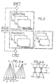
- Figures 3a and 3b show in a comparative manner the acquisition modes in the state of the art and in the invention respectively.
- the acquisition of an image occurred when the X-ray tube-multidetector assembly carried out turns on itself such as the turns 26. After each turn, a slight translation 27 made it possible to place the whole plumb with another section of the body to be examined.
- the roll bar 6 is subjected to slight stepping rotations 28 (shown here in an exaggerated manner), and, between each step, inside the cowlings 92 and 94, l 'X-ray tube 2-multidetector 4 assembly is subjected to translations such as 29.
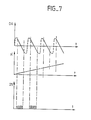
- FIGS. 4a to 4c show respectively, over time, the rotation steps ⁇ of the cowlings 92 and 94, the alternative displacements DA of the assembly 1 in the cowlings, as well as the timing of the orders 25.
- the rollovers are fixed ( ⁇ does not vary), the displacement is linear (DA follows a regular ramp), and the number of orders 25 corresponds substantially to the number of slices to be acquired during the entire duration of the scan. This number also corresponds to the longitudinal resolution to be obtained. For example on 250 millimeters, with a resolution of 1 millimeter, there are 250 timing pulses 25.
- the preferred embodiment corresponds to FIG. 7, that is to say a continuous rotation and an asymmetrical movement of the translation.
- This asymmetrical movement comprises a slow movement during acquisition in a direction tolerated by the detector, and a rapid return movement in a direction where the detector is inactive.
- FIG. 5 shows a particular feature of the mode of acquisition and reconstruction of the images obtained according to the invention.
- the acquisition of a view V1 is normally conventionally followed by a rear projection R1, making it possible to define in a first phase a corresponding image I1.
- the tomograph turns on itself, it then acquires views V′1 then V ⁇ 1 ... which are transformed by rear projection operations R′1 then R ⁇ 1 ... in order to complete the definition of l 'image I1.
- the tomograph of the state of the art is translated (27) directly above the next section and the process is restarted.
- the rear projection algorithm that can be used will be the same. Quite simply between the acquisition of a view V1 and the acquisition of the following view V′1 corresponding to the same section in the object, we will have, by the play of the scanning translation 29, acquired sections V2. ..V N which are respectively subjected to backprojections R2 ... R N in order to define in a first pass the other images I2 ... I N (in the example N is worth 250). The consequence of this situation is that in practical terms, the memory capacities and the processing algorithms are the same. Only the organization of the acquisition changes (in correspondence.
- FIG. 2 shows an ideal type of radiation in which the X-ray source is not point-like but is extended over a distance AB and in which the radiation is of the parallel type. The reality is different, and the source of X-rays is point-like.
- Figure 6a there is shown, during a translation, the part actually irradiated and taken into consideration of the body examined.
- a first position 31, of the X-ray source has been shown, as well as an alignment of cells 32 to 36 belonging, for example, respectively to rows 19 to 23 of the multirange multidetector of FIG. 2.
- Each time the X-ray source moves to an adjacent position, for example positions 37 to 40 the electrical contents of cells 36 to 32 are shifted in opposite direction: i.e. from cell 36 to cell 32.
- the studied part of the object is not perfectly a flat slice as suggested by slice 18 of FIG. 2, but is on the contrary a slice of trapezoidal section whose large base is equal to the width of the multi-line multidetector and whose small base is equal to the width of one of the rows of the multi-line multidetector. It is deduced therefrom that a multirange detector with too many rows or a detector that is too wide cannot be used under these conditions. The number of rows equal to 5 seems to be a good compromise from this point of view.
Landscapes
- Health & Medical Sciences (AREA)
- Life Sciences & Earth Sciences (AREA)
- Engineering & Computer Science (AREA)
- Medical Informatics (AREA)
- Optics & Photonics (AREA)
- Biomedical Technology (AREA)
- Biophysics (AREA)
- High Energy & Nuclear Physics (AREA)
- Theoretical Computer Science (AREA)
- Nuclear Medicine, Radiotherapy & Molecular Imaging (AREA)
- Pulmonology (AREA)
- Pathology (AREA)
- Radiology & Medical Imaging (AREA)
- Physics & Mathematics (AREA)
- Heart & Thoracic Surgery (AREA)
- Molecular Biology (AREA)
- Surgery (AREA)
- Animal Behavior & Ethology (AREA)
- General Health & Medical Sciences (AREA)
- Public Health (AREA)
- Veterinary Medicine (AREA)
- Apparatus For Radiation Diagnosis (AREA)
- Analysing Materials By The Use Of Radiation (AREA)
Applications Claiming Priority (2)
| Application Number | Priority Date | Filing Date | Title |
|---|---|---|---|
| FR8806138 | 1988-05-06 | ||
| FR8806138A FR2630903A1 (fr) | 1988-05-06 | 1988-05-06 | Dispositif de tomographie a grande cadence d'acquisition |
Publications (1)
| Publication Number | Publication Date |
|---|---|
| EP0341143A1 true EP0341143A1 (de) | 1989-11-08 |
Family
ID=9366083
Family Applications (1)
| Application Number | Title | Priority Date | Filing Date |
|---|---|---|---|
| EP89401219A Withdrawn EP0341143A1 (de) | 1988-05-06 | 1989-04-28 | Gerät und Verfahren zur Tomographie mit erhöhter Aufnahmgeschwindigkeit |
Country Status (4)
| Country | Link |
|---|---|
| US (1) | US5022060A (de) |
| EP (1) | EP0341143A1 (de) |
| JP (1) | JPH0217042A (de) |
| FR (1) | FR2630903A1 (de) |
Cited By (1)
| Publication number | Priority date | Publication date | Assignee | Title |
|---|---|---|---|---|
| WO1999007283A1 (en) * | 1997-08-06 | 1999-02-18 | Picker Medical Systems, Ltd. | Cardiac imaging |
Families Citing this family (18)
| Publication number | Priority date | Publication date | Assignee | Title |
|---|---|---|---|---|
| IL90521A0 (en) * | 1989-06-04 | 1990-01-18 | Elscint Ltd | Dual slice scanner |
| JPH0620450B2 (ja) * | 1990-04-06 | 1994-03-23 | 株式会社東芝 | X線断層撮影装置 |
| JPH0620449B2 (ja) * | 1990-04-06 | 1994-03-23 | 株式会社東芝 | X線断層撮影装置 |
| JPH0710255B2 (ja) * | 1990-04-06 | 1995-02-08 | 株式会社東芝 | X線断層撮影装置 |
| JP2593576B2 (ja) * | 1990-07-31 | 1997-03-26 | 株式会社東芝 | 放射線位置決め装置 |
| JPH074356B2 (ja) * | 1993-04-19 | 1995-01-25 | 株式会社東芝 | X線断層撮影装置 |
| JPH074355B2 (ja) * | 1993-04-19 | 1995-01-25 | 株式会社東芝 | X線断層撮影装置 |
| DE19606867A1 (de) * | 1996-02-23 | 1997-08-28 | Siemens Ag | Röntgen-Computertomograph |
| JP2000271110A (ja) * | 1999-03-26 | 2000-10-03 | Hitachi Medical Corp | 医用x線装置 |
| DE10007306A1 (de) * | 2000-02-17 | 2001-08-23 | Macrotron Process Technologies | Röntgensystem |
| EP1347309A3 (de) * | 2002-03-20 | 2012-04-18 | Hitachi, Ltd. | Radiologische, bildgebende Vorrichtung und Verfahren |
| EP1624804B1 (de) * | 2003-05-14 | 2011-10-05 | Koninklijke Philips Electronics N.V. | Verfahren und apparat zur verbesserten strahlendetektion |
| SE527138C2 (sv) | 2003-07-08 | 2005-12-27 | Xcounter Ab | Skanningsbaserad detektering av joniserande strålning för tomosyntes |
| SE527976C2 (sv) * | 2004-01-08 | 2006-07-25 | Xcounter Ab | Skanningsbaserad detektering av joniserande strålning för tomosyntes |
| US20050265523A1 (en) * | 2004-05-28 | 2005-12-01 | Strobel Norbert K | C-arm device with adjustable detector offset for cone beam imaging involving partial circle scan trajectories |
| US7180977B2 (en) * | 2005-10-24 | 2007-02-20 | Xcounter Ab | Scanning-based detection of ionizing radiaion for tomosynthesis |
| SE0702258L (sv) * | 2007-10-09 | 2009-03-31 | Xcounter Ab | Anordning och metod för att upptaga strålningsbilddata av ett objekt |
| WO2009104156A1 (en) * | 2008-02-22 | 2009-08-27 | Philips Intellectual Property & Standards Gmbh | High-resolution quasi-static setup for x-ray imaging with distributed sources |
Citations (4)
| Publication number | Priority date | Publication date | Assignee | Title |
|---|---|---|---|---|
| US4063097A (en) * | 1976-09-16 | 1977-12-13 | General Electric Company | X-ray body scanner for computerized tomography comprising inner fluid container surrounded by outer fluid container |
| EP0024028A1 (de) * | 1979-08-08 | 1981-02-18 | Siemens Aktiengesellschaft | Röntgengerät zur Herstellung von Transversalschichtbildern und Röntgenschattenbildern eines Aufnahmeobjektes |
| EP0051350A2 (de) * | 1980-10-31 | 1982-05-12 | Technicare Corporation | Abtastblende zur Darstellung einer Absorptionsverteilung mittels eines Sichtgerätes |
| EP0099018A1 (de) * | 1982-06-30 | 1984-01-25 | Siemens Aktiengesellschaft | Ultraschall-Tomographiegerät |
Family Cites Families (9)
| Publication number | Priority date | Publication date | Assignee | Title |
|---|---|---|---|---|
| US3121793A (en) * | 1961-03-15 | 1964-02-18 | Westinghouse Electric Corp | Movable x-ray tube support apparatus |
| US3803417A (en) * | 1971-05-13 | 1974-04-09 | Philips Corp | X-ray apparatus for heart catheterization and other procedures |
| US3976885A (en) * | 1975-03-18 | 1976-08-24 | Picker Corporation | Tomography system having nonconcurrent, compound axial scanning |
| DE2613809B2 (de) * | 1976-03-31 | 1979-01-04 | Siemens Ag, 1000 Berlin Und 8000 Muenchen | Röntgenschichtgerät zur Herstellung von Transversal-Schichtbildern |
| US4363128A (en) * | 1980-09-29 | 1982-12-07 | John K. Grady | X-Ray drive apparatus |
| US4358856A (en) * | 1980-10-31 | 1982-11-09 | General Electric Company | Multiaxial x-ray apparatus |
| JPS59111738A (ja) * | 1982-12-16 | 1984-06-28 | 株式会社東芝 | X線断層撮影装置 |
| JPS61209641A (ja) * | 1985-03-15 | 1986-09-17 | 株式会社東芝 | X線ct装置 |
| US4829547A (en) * | 1987-05-01 | 1989-05-09 | Liebel-Flarsheim | Method and apparatus for taking tomographic X-rays |
-
1988
- 1988-05-06 FR FR8806138A patent/FR2630903A1/fr not_active Withdrawn
-
1989
- 1989-04-28 EP EP89401219A patent/EP0341143A1/de not_active Withdrawn
- 1989-05-02 US US07/346,599 patent/US5022060A/en not_active Expired - Fee Related
- 1989-05-06 JP JP1114011A patent/JPH0217042A/ja active Pending
Patent Citations (4)
| Publication number | Priority date | Publication date | Assignee | Title |
|---|---|---|---|---|
| US4063097A (en) * | 1976-09-16 | 1977-12-13 | General Electric Company | X-ray body scanner for computerized tomography comprising inner fluid container surrounded by outer fluid container |
| EP0024028A1 (de) * | 1979-08-08 | 1981-02-18 | Siemens Aktiengesellschaft | Röntgengerät zur Herstellung von Transversalschichtbildern und Röntgenschattenbildern eines Aufnahmeobjektes |
| EP0051350A2 (de) * | 1980-10-31 | 1982-05-12 | Technicare Corporation | Abtastblende zur Darstellung einer Absorptionsverteilung mittels eines Sichtgerätes |
| EP0099018A1 (de) * | 1982-06-30 | 1984-01-25 | Siemens Aktiengesellschaft | Ultraschall-Tomographiegerät |
Cited By (1)
| Publication number | Priority date | Publication date | Assignee | Title |
|---|---|---|---|---|
| WO1999007283A1 (en) * | 1997-08-06 | 1999-02-18 | Picker Medical Systems, Ltd. | Cardiac imaging |
Also Published As
| Publication number | Publication date |
|---|---|
| JPH0217042A (ja) | 1990-01-22 |
| US5022060A (en) | 1991-06-04 |
| FR2630903A1 (fr) | 1989-11-10 |
Similar Documents
| Publication | Publication Date | Title |
|---|---|---|
| FR2630903A1 (fr) | Dispositif de tomographie a grande cadence d'acquisition | |
| JP5268499B2 (ja) | 計算機式断層写真法(ct)イメージング・システム | |
| US7046756B2 (en) | Rotatable filter for a pre-subject CT collimator having multiple filtering profiles | |
| EP2240080B1 (de) | Zahnröntgengerät und entsprechendes verfahren | |
| JP4314008B2 (ja) | X線ctスキャナ | |
| US6968030B2 (en) | Method and apparatus for presenting multiple pre-subject filtering profiles during CT data acquisition | |
| JP2015522154A (ja) | 画像診断システム及び作動方法 | |
| US4008400A (en) | Transverse tomography system having multibeam orbital scanning with all beams offset from the center of orbit | |
| CN102462505B (zh) | 用于宽覆盖和低剂量心脏ct成像的动态准直器 | |
| JP6371033B2 (ja) | 計算機式断層写真法(ct)撮像での投与線量低減の方法、及び該方法を実装した装置 | |
| FR2938182A1 (fr) | Appareil de radiologie dentaire et procede d'utilisation associe | |
| EP0011897A1 (de) | Einrichtung zur tomographischen Abtastung eines Körpers mittels Röntgen- oder Gamma-Strahlen | |
| CN1689525A (zh) | 在剂量减小的分段式螺旋扫描中再现投影数据组的方法 | |
| EP0795763B1 (de) | Vorrichtung zur Transversabschichtbildern | |
| EP0517602B1 (de) | Gammakamera mit zwei gegenseitigen Detektoren und unabhängigen Radialbewegungen | |
| WO2016007605A1 (en) | System and method for motion-free computed tomography | |
| FR2549711A1 (fr) | Appareil de tomographie informatisee et son procede de commande | |
| FR2565092A1 (fr) | Scanographe comportant un faisceau en eventail rotatif et une couronne de detecteurs non rotative | |
| EP1132757B1 (de) | Gammakameras mit korrigierter Transmissionsstrahlung | |
| US4117336A (en) | Computerized radiography with means to process only selected signals | |
| US7860211B1 (en) | Method of producing a laminography image with a rotating object, fixed x-ray source, and fixed detector columns | |
| EP0764855A2 (de) | Verfahren zur Erzeugung eines Nuklearmedizin-Körperbildes mit Abstrumpfungsfehlerkorrigierung | |
| JP4114467B2 (ja) | X線ct装置 | |
| US4126785A (en) | Radiography | |
| EP1902423B1 (de) | Röntgen- oder infrarot-bildgebungsverfahren und -einrichtung |
Legal Events
| Date | Code | Title | Description |
|---|---|---|---|
| PUAI | Public reference made under article 153(3) epc to a published international application that has entered the european phase |
Free format text: ORIGINAL CODE: 0009012 |
|
| AK | Designated contracting states |
Kind code of ref document: A1 Designated state(s): DE ES GB IT NL |
|
| 17P | Request for examination filed |
Effective date: 19900129 |
|
| 17Q | First examination report despatched |
Effective date: 19900625 |
|
| STAA | Information on the status of an ep patent application or granted ep patent |
Free format text: STATUS: THE APPLICATION IS DEEMED TO BE WITHDRAWN |
|
| 18D | Application deemed to be withdrawn |
Effective date: 19911008 |