EP0341359A1 - Coques de bateaux - Google Patents
Coques de bateaux Download PDFInfo
- Publication number
- EP0341359A1 EP0341359A1 EP88304348A EP88304348A EP0341359A1 EP 0341359 A1 EP0341359 A1 EP 0341359A1 EP 88304348 A EP88304348 A EP 88304348A EP 88304348 A EP88304348 A EP 88304348A EP 0341359 A1 EP0341359 A1 EP 0341359A1
- Authority
- EP
- European Patent Office
- Prior art keywords
- channels
- hull
- aperture
- recess
- walls
- Prior art date
- Legal status (The legal status is an assumption and is not a legal conclusion. Google has not performed a legal analysis and makes no representation as to the accuracy of the status listed.)
- Withdrawn
Links
- XLYOFNOQVPJJNP-UHFFFAOYSA-N water Substances O XLYOFNOQVPJJNP-UHFFFAOYSA-N 0.000 claims abstract description 34
- 230000002093 peripheral effect Effects 0.000 claims abstract description 5
- 239000012530 fluid Substances 0.000 claims 1
- 230000000630 rising effect Effects 0.000 claims 1
- 230000000694 effects Effects 0.000 description 6
- 230000008901 benefit Effects 0.000 description 4
- 239000002245 particle Substances 0.000 description 3
- 238000007789 sealing Methods 0.000 description 2
- 230000002411 adverse Effects 0.000 description 1
- 244000221110 common millet Species 0.000 description 1
- 210000004744 fore-foot Anatomy 0.000 description 1
- 238000000034 method Methods 0.000 description 1
Images

Classifications
-
- B—PERFORMING OPERATIONS; TRANSPORTING
- B63—SHIPS OR OTHER WATERBORNE VESSELS; RELATED EQUIPMENT
- B63B—SHIPS OR OTHER WATERBORNE VESSELS; EQUIPMENT FOR SHIPPING
- B63B1/00—Hydrodynamic or hydrostatic features of hulls or of hydrofoils
- B63B1/32—Other means for varying the inherent hydrodynamic characteristics of hulls
- B63B1/34—Other means for varying the inherent hydrodynamic characteristics of hulls by reducing surface friction
- B63B1/38—Other means for varying the inherent hydrodynamic characteristics of hulls by reducing surface friction using air bubbles or air layers gas filled volumes
-
- Y—GENERAL TAGGING OF NEW TECHNOLOGICAL DEVELOPMENTS; GENERAL TAGGING OF CROSS-SECTIONAL TECHNOLOGIES SPANNING OVER SEVERAL SECTIONS OF THE IPC; TECHNICAL SUBJECTS COVERED BY FORMER USPC CROSS-REFERENCE ART COLLECTIONS [XRACs] AND DIGESTS
- Y02—TECHNOLOGIES OR APPLICATIONS FOR MITIGATION OR ADAPTATION AGAINST CLIMATE CHANGE
- Y02T—CLIMATE CHANGE MITIGATION TECHNOLOGIES RELATED TO TRANSPORTATION
- Y02T70/00—Maritime or waterways transport
- Y02T70/10—Measures concerning design or construction of watercraft hulls
Definitions
- This invention relates to improvements in a marine hull, and is not necessarily limited to high speed hulls but the invention is particularly applicable thereto.
- the most commonly used planing hulls for marine purposes have substantially constant dead rises aft of about station 4 or 5, in order to reduce the suction load which can occur with a "hooked" style of hull bottom.
- a constant dead rise however the loading between the surface of the hull bottom and the water is usually positive for most of the length of the hull (that is, there is a kinetic energy imparted to the water due to deflection of the particles of water encountered by the hull bottom surface, having a downward component of movement.
- the trim angle is therefore critical).
- a marine hull has a forebody, a transom, and a bottom extending therebetween having walls defining a plurality of upwardly formed channels between the forebody and the transom, the channels diverging in a rearward direction, air entry means near the front ends of the channels, and the rear ends of at least some of said channels opening at a peripheral edge of said bottom whereby water in these channels is free to discharge therefrom in a rearward and outward direction.
- the downwardly facing open channels allow air to enter the channels along with the water.
- a relatively low pressure area which exists beneath the hull when the hull is in motion through the water will induce a flow of air through the air entry means, or through an air flow aperture.
- air entry means could alternatively comprise "exit paths" between adjacent channels. That flow of air performs an important function of substantially reducing the suction load on the hull when the hull is moving, so that the negative effects of suction can be very substantially reduced and in some instances almost be eliminated. This is further assisted by the movement of water through the channels which also induces flow of air into the channels.
- the air performs a secondary function of allowing the water to flow upwardly into the channels and to be deflected downwardly by the channel walls.
- the channels become "choked" with water which merely flows longitudinally through them, and the hull performance will be only marginally better than could be achieved with a conventional hard chine bottom.
- the invention can further include two facilities to limit this hydraulic hammering or thumping so that it is less disturbing than that produced by present monohulls.
- the front ends of the channels least likely to be affected have increased depth, providing "air cushion chambers".
- exit paths can exist between adjacent channels near their front ends, and allow the forwardly moving water to move from lower into higher channels, from which that water can be readily redirected away from the hull.
- a marine hull bottom comprises walls defining an upwardly extending recess therein, the walls extending into the hull located between the forebody and transom of the hull, there being an aperture through a said recess wall, said aperture being in the lower portion of that wall, and further walls within the hull defining a passageway for air flow to the aperture from within the hull.
- the further walls can for example be the walls of a compartment having peripheral edges sealed with respect to the hull, the location of the compartment being over the recess and near or joined to the transom.
- the invention is applicable to most hulls wherein an hydraulic lift effect is desirable. Obviously, if there is no divergance of channels, the running lines will be straight, there will be no upward, outward and downward deflection of the water particles, and the effect of the channels would be merely to assist the hull in "tracking", this arrangement being well known.
- the angle of divergence from the central longitudinal plane can be as much as 45° (90° included angle) before the benefits cease to be viable.
- the invention can be of value in racing craft by providing lift near the transom, sometimes with a divergence angle as little as 3°.
- the angle of divergence can be about 15°, as herein illustrated.
- the invention has a number of advantages over the known prior art:-
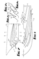
- a hull 10 comprises a forebody 11, a transom 12, and a bottom 13 extending therebetween.
- the bottom 13 is provided with a plurality of channels 14 which diverge rearwardly.
- Two intermediate channels 14 extend from the forebody and open at their rear ends to the chines 15. The innermost channel 14 opens to the transom 12. The channels are not shown in Figs. 4 or 7.
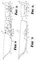
- the walls 17, 18 and 19 extend upwardly into the hull from the bottom 13 and define a recess 20.
- the wall 17 is a rearwardly facing wall and that wall contains an aperture 21 which is in an area of the hull bottom 13 likely to be a low pressure area in any case, but in being a rearwardly facing wall in the recess 20 it is in an even lower pressure area.
- the aperture 21 is situated as low as possible to allow a large volume of air to be trapped in the recess above the aperture. Additional apertures 21 are situated in laterally extending stepped portions of walls 18 and 19 to allow greater air flow.
- the recess forms the forward end of a V-shaped channel 22 which is similar to the channels 14 in cross-sectional shape, and diverges rearwardly to open to the transom 12 as seen best in Fig. 2, allowing a free through flow of water from the channel.
- the stepped portions containing apertures 21 are forward of the V-shaped channel 22.
- the outer walls of channel 22 contain still further air apertures 21 (Fig. 4), which are immediately adjacent vertical steps located at the point of commencement of channel divergence.
- the hull contains compartment walls 25 which surround and overlie the walls 17, 18 and 19 so that the aperture 21 opens into the compartment 26.
- This compartment contains a baffle 27 which inhibits fore-and-aft water movement in compartment 26 and has drainage holes 28 which can be closed by valve means 29 (shown only diagrammatically).
- Transom 12 contains air entry apertures 30 closable by valves 31, but when open allow air into or out of the compartment 26. Only one valve 31 needs to be installed.
- An air pump 32 is effective in expelling water from compartment 26 (if required). When the hull is in motion in the water, the water contained in compartment 26 will drain.
- the effective mass of the craft is reduced when the craft is in motion but increased when the compartment 26 is filled with water, that is, when the vessel is at rest. If the valves 31 are closed when the compartment 26 is empty, the air can be trapped within the compartment and the effective draft of the vessel can be substantially reduced at low speeds.
- transducers In many boats, use is made of transducers, earthing plates for radios and the like, and by having for example a transducer 38 in the hull bottom, the problems of sealing are removed, the transducer 38 being connected by a cable 39 to an a echo sounder 40 routed via a tube with the upper opening above the waterline (shown only diagrammatically in Fig. 4).
- Fig. 7 when using power units other than an outboard, increased weight forward must generally be carried as in the case of a stern drive or inboard motor, thus needing more buoyancy, and these units would be mounted as shown in Fig. 7, in the same general position as compartment 26.
- the compartment 26 can be eliminated and the airflow to aperture 21 in recess 20 can be delivered via a pipe 43 following the path of the stem and the keelson.
- the pipe also acts as a structural member to strengthen the forward portion of the hull.
- dotted lines 14a in Fig. 2 illustrate the upper-limits of channels 14, and show how the upper three channels increase in depth at their front ends, to provide "air entrapment" means which will reduce water-hammer in the channels which are only intermittently submerged.
- the lower channels 14 however are more often submerged (although their front ends constitute air entry means). At, or near, the front ends of channels 14, their outer side walls are interrupted to provide "exit paths" 45 for forwardly moving water, which will move outwardly and upwardly from the inner, lower channels 14 to those above them. For these paths to be effective, they should be oriented as shown in Fig. 2 to direct water flow rearwardly into the outer channels.
- Each front end 46 of the rearwardly extending channel walls approximates the shape of a quarter sphere, but the rearward facing walls 47 are concave in plan such that in conjunction with end 46, a non-constrictive path is formed between adjacent channels. Additional exit paths per channel exist further aft in some instances.
- Extensions 48 of the four inner, lower channels 14 comprise short, narrow triangular lands 48, which assist in deflecting the bow wave outwardly at the forefoot.
- the channels 14 are arranged to be symmetrical with respect to a central longitudinal plane of the boat hull 10, and to diverge rearwardly at an angle thereto not less than 3° nor more than 45° (that is, 7° and 90° inclusive respectively).
- Any suitably shaped hull can have its sea keeping characteristics modified by modifying the shapes and divergence of the channels. For example, more channel area near the after end will provide more dynamic lift at that end, increase the wetted area of the hull, and reduce the trim angle (requirements for ocean going vessels).
- Softness of ride is obtained when the trim attitude of the hull is such that the top of the front end of one or more pairs of channels is lower than the top of the rear of those channels.
- Positioning the lowermost channel pair 14 and therefore also pair 22 towards the stern provides a greater bias of lift to the rear so that the whole boat rides high at the stern when at speed. The channels will then slope upward to the rear.
Landscapes
- Physics & Mathematics (AREA)
- Fluid Mechanics (AREA)
- Chemical & Material Sciences (AREA)
- Engineering & Computer Science (AREA)
- Combustion & Propulsion (AREA)
- Mechanical Engineering (AREA)
- Ocean & Marine Engineering (AREA)
- Other Liquid Machine Or Engine Such As Wave Power Use (AREA)
Priority Applications (1)
| Application Number | Priority Date | Filing Date | Title |
|---|---|---|---|
| EP88304348A EP0341359A1 (fr) | 1988-05-13 | 1988-05-13 | Coques de bateaux |
Applications Claiming Priority (1)
| Application Number | Priority Date | Filing Date | Title |
|---|---|---|---|
| EP88304348A EP0341359A1 (fr) | 1988-05-13 | 1988-05-13 | Coques de bateaux |
Publications (1)
| Publication Number | Publication Date |
|---|---|
| EP0341359A1 true EP0341359A1 (fr) | 1989-11-15 |
Family
ID=8200066
Family Applications (1)
| Application Number | Title | Priority Date | Filing Date |
|---|---|---|---|
| EP88304348A Withdrawn EP0341359A1 (fr) | 1988-05-13 | 1988-05-13 | Coques de bateaux |
Country Status (1)
| Country | Link |
|---|---|
| EP (1) | EP0341359A1 (fr) |
Cited By (2)
| Publication number | Priority date | Publication date | Assignee | Title |
|---|---|---|---|---|
| WO2014200407A1 (fr) * | 2013-06-11 | 2014-12-18 | Petestep Ab | Embarcation dotée d'une coque planante |
| CN109572923A (zh) * | 2019-01-21 | 2019-04-05 | 威海市金运游艇有限公司 | 一种槽道滑行艇 |
Citations (6)
| Publication number | Priority date | Publication date | Assignee | Title |
|---|---|---|---|---|
| US3316874A (en) * | 1964-10-09 | 1967-05-02 | Canazzi Henry Donald | Boat hulls |
| US3547064A (en) * | 1968-08-21 | 1970-12-15 | Cava Ind | Planing step |
| FR2522556A1 (en) * | 1981-12-03 | 1983-09-09 | Pimoule Roger | Marine vessel hull with wave propulsion - converts vertical force of sea swell into horizontal force aiding propulsion using grooves on hull |
| EP0088640A2 (fr) * | 1982-03-09 | 1983-09-14 | Akira Ikeda | Navire avec l'échappement par le fond |
| WO1987001350A1 (fr) * | 1985-08-26 | 1987-03-12 | Small Mark S | Deflecteur de tunnel d'helice et procede |
| US4708085A (en) * | 1984-12-06 | 1987-11-24 | Blee Leonard J | Marine hull |
-
1988
- 1988-05-13 EP EP88304348A patent/EP0341359A1/fr not_active Withdrawn
Patent Citations (6)
| Publication number | Priority date | Publication date | Assignee | Title |
|---|---|---|---|---|
| US3316874A (en) * | 1964-10-09 | 1967-05-02 | Canazzi Henry Donald | Boat hulls |
| US3547064A (en) * | 1968-08-21 | 1970-12-15 | Cava Ind | Planing step |
| FR2522556A1 (en) * | 1981-12-03 | 1983-09-09 | Pimoule Roger | Marine vessel hull with wave propulsion - converts vertical force of sea swell into horizontal force aiding propulsion using grooves on hull |
| EP0088640A2 (fr) * | 1982-03-09 | 1983-09-14 | Akira Ikeda | Navire avec l'échappement par le fond |
| US4708085A (en) * | 1984-12-06 | 1987-11-24 | Blee Leonard J | Marine hull |
| WO1987001350A1 (fr) * | 1985-08-26 | 1987-03-12 | Small Mark S | Deflecteur de tunnel d'helice et procede |
Cited By (4)
| Publication number | Priority date | Publication date | Assignee | Title |
|---|---|---|---|---|
| WO2014200407A1 (fr) * | 2013-06-11 | 2014-12-18 | Petestep Ab | Embarcation dotée d'une coque planante |
| US10293886B2 (en) | 2013-06-11 | 2019-05-21 | Petestep Ab | Watercraft vessel with a planing hull |
| CN109572923A (zh) * | 2019-01-21 | 2019-04-05 | 威海市金运游艇有限公司 | 一种槽道滑行艇 |
| CN109572923B (zh) * | 2019-01-21 | 2023-10-13 | 威海市金运游艇有限公司 | 一种槽道滑行艇 |
Similar Documents
| Publication | Publication Date | Title |
|---|---|---|
| US5215025A (en) | Boat | |
| US4231314A (en) | Hydroplane boat | |
| US7418915B2 (en) | Entrapment tunnel monohull optimized waterjet and high payload | |
| KR101117038B1 (ko) | 공기 캐비티 선박 | |
| US5031556A (en) | Marine hull | |
| US6293216B1 (en) | Surface effect ship (SES) hull configuration having improved high speed performance and handling characteristics | |
| US4708085A (en) | Marine hull | |
| US5522333A (en) | Catamaran boat with planing pontoons | |
| AU4065299A (en) | High speed hybrid marine vessel | |
| US3342154A (en) | Boats | |
| AU3861789A (en) | Improved hull construction for a swath vessel | |
| US5301624A (en) | Stern planes for swath vessel | |
| US20090308300A1 (en) | Watercraft with wave deflecting hull | |
| US6176196B1 (en) | Boat bottom hull design | |
| US5526762A (en) | Power planing catamaran | |
| EP0585698B1 (fr) | Construction de coque de bateau rapide avec stabilité latérale | |
| US4708077A (en) | Hull shapes for surface effect ship with side walls and two modes of operation | |
| US3331347A (en) | Boats comprising means for introducing air to submerged portions of the boat bottom | |
| EP0341359A1 (fr) | Coques de bateaux | |
| US7316193B1 (en) | Vessel for water travel | |
| US5317982A (en) | Ship | |
| US4340004A (en) | High-speed ship | |
| AU610094B2 (en) | Improvements to maring hull | |
| US20060144312A1 (en) | Watercraft with wave deflecting hull | |
| US6948439B2 (en) | Surface effect ship improvements |
Legal Events
| Date | Code | Title | Description |
|---|---|---|---|
| PUAI | Public reference made under article 153(3) epc to a published international application that has entered the european phase |
Free format text: ORIGINAL CODE: 0009012 |
|
| AK | Designated contracting states |
Kind code of ref document: A1 Designated state(s): DE FR GB IT |
|
| 17P | Request for examination filed |
Effective date: 19900410 |
|
| 17Q | First examination report despatched |
Effective date: 19910326 |
|
| STAA | Information on the status of an ep patent application or granted ep patent |
Free format text: STATUS: THE APPLICATION IS DEEMED TO BE WITHDRAWN |
|
| 18D | Application deemed to be withdrawn |
Effective date: 19910806 |