EP0341390A2 - Dispositif de piston pour une unité de piston - Google Patents
Dispositif de piston pour une unité de piston Download PDFInfo
- Publication number
- EP0341390A2 EP0341390A2 EP89104147A EP89104147A EP0341390A2 EP 0341390 A2 EP0341390 A2 EP 0341390A2 EP 89104147 A EP89104147 A EP 89104147A EP 89104147 A EP89104147 A EP 89104147A EP 0341390 A2 EP0341390 A2 EP 0341390A2
- Authority
- EP
- European Patent Office
- Prior art keywords
- piston
- curvature
- coupling member
- sliding block
- coupling
- Prior art date
- Legal status (The legal status is an assumption and is not a legal conclusion. Google has not performed a legal analysis and makes no representation as to the accuracy of the status listed.)
- Granted
Links
Images
Classifications
-
- F—MECHANICAL ENGINEERING; LIGHTING; HEATING; WEAPONS; BLASTING
- F16—ENGINEERING ELEMENTS AND UNITS; GENERAL MEASURES FOR PRODUCING AND MAINTAINING EFFECTIVE FUNCTIONING OF MACHINES OR INSTALLATIONS; THERMAL INSULATION IN GENERAL
- F16J—PISTONS; CYLINDERS; SEALINGS
- F16J1/00—Pistons; Trunk pistons; Plungers
- F16J1/10—Connection to driving members
- F16J1/14—Connection to driving members with connecting-rods, i.e. pivotal connections
- F16J1/22—Connection to driving members with connecting-rods, i.e. pivotal connections with universal joint, e.g. ball-joint
-
- F—MECHANICAL ENGINEERING; LIGHTING; HEATING; WEAPONS; BLASTING
- F04—POSITIVE - DISPLACEMENT MACHINES FOR LIQUIDS; PUMPS FOR LIQUIDS OR ELASTIC FLUIDS
- F04B—POSITIVE-DISPLACEMENT MACHINES FOR LIQUIDS; PUMPS
- F04B1/00—Multi-cylinder machines or pumps characterised by number or arrangement of cylinders
- F04B1/04—Multi-cylinder machines or pumps characterised by number or arrangement of cylinders having cylinders in star- or fan-arrangement
- F04B1/0404—Details or component parts
- F04B1/0408—Pistons
-
- F—MECHANICAL ENGINEERING; LIGHTING; HEATING; WEAPONS; BLASTING
- F04—POSITIVE - DISPLACEMENT MACHINES FOR LIQUIDS; PUMPS FOR LIQUIDS OR ELASTIC FLUIDS
- F04B—POSITIVE-DISPLACEMENT MACHINES FOR LIQUIDS; PUMPS
- F04B1/00—Multi-cylinder machines or pumps characterised by number or arrangement of cylinders
- F04B1/12—Multi-cylinder machines or pumps characterised by number or arrangement of cylinders having cylinder axes coaxial with, or parallel or inclined to, main shaft axis
- F04B1/122—Details or component parts, e.g. valves, sealings or lubrication means
- F04B1/124—Pistons
-
- F—MECHANICAL ENGINEERING; LIGHTING; HEATING; WEAPONS; BLASTING
- F05—INDEXING SCHEMES RELATING TO ENGINES OR PUMPS IN VARIOUS SUBCLASSES OF CLASSES F01-F04
- F05B—INDEXING SCHEME RELATING TO WIND, SPRING, WEIGHT, INERTIA OR LIKE MOTORS, TO MACHINES OR ENGINES FOR LIQUIDS COVERED BY SUBCLASSES F03B, F03D AND F03G
- F05B2230/00—Manufacture
- F05B2230/40—Heat treatment
- F05B2230/41—Hardening; Annealing
-
- F—MECHANICAL ENGINEERING; LIGHTING; HEATING; WEAPONS; BLASTING
- F05—INDEXING SCHEMES RELATING TO ENGINES OR PUMPS IN VARIOUS SUBCLASSES OF CLASSES F01-F04
- F05C—INDEXING SCHEME RELATING TO MATERIALS, MATERIAL PROPERTIES OR MATERIAL CHARACTERISTICS FOR MACHINES, ENGINES OR PUMPS OTHER THAN NON-POSITIVE-DISPLACEMENT MACHINES OR ENGINES
- F05C2201/00—Metals
- F05C2201/04—Heavy metals
- F05C2201/0469—Other heavy metals
- F05C2201/0475—Copper or alloys thereof
- F05C2201/0478—Bronze (Cu/Sn alloy)
-
- F—MECHANICAL ENGINEERING; LIGHTING; HEATING; WEAPONS; BLASTING
- F05—INDEXING SCHEMES RELATING TO ENGINES OR PUMPS IN VARIOUS SUBCLASSES OF CLASSES F01-F04
- F05C—INDEXING SCHEME RELATING TO MATERIALS, MATERIAL PROPERTIES OR MATERIAL CHARACTERISTICS FOR MACHINES, ENGINES OR PUMPS OTHER THAN NON-POSITIVE-DISPLACEMENT MACHINES OR ENGINES
- F05C2253/00—Other material characteristics; Treatment of material
- F05C2253/12—Coating
Definitions
- the invention relates to a piston device for a piston unit, in particular a hydraulic pump or hydraulic motor with at least one piston guided in a cylinder, which is acted upon by a pressure medium on one end face and is provided on the other end face with a sliding shoe interacting via a ball joint, and via the sliding shoe is supported on a support surface, the piston and the sliding block being connected and held together by a coupling member provided with a longitudinal bore, which is provided at its ends with an articulated head, which is part of a coupling arranged inside the piston and the sliding block -Ball joint is formed.
- the area of application of such piston devices extends above all to the area of piston units which are used as an engine or machine.
- the working medium is a pressurized gas, for example air, or a pressurized fluid, for example a hydraulic oil.
- Piston devices for such piston units are known in various designs.
- the piston guided in a cylinder bore is supported on the end face via a ball joint on a sliding shoe.
- the slide shoe in turn is supported on a support surface, the slide shoe and the support surface moving relative to one another.
- the piston and the sliding block are connected to one another by a coupling member which has spherical zone-shaped heads at its ends, the spherical surfaces of which interact with concave spherical surfaces arranged inside the piston and the sliding block, so that the piston and the sliding block are held together. Since relative movements occur between the sliding shoe and the piston and thus in the ball joint during the operation of such a piston unit, it is necessary for the coupling member to permit such a movement. Such a movement is now possible in the known embodiment, but the two oppositely directed spherical-zone-shaped heads cause clamping effects or play in the articulated surfaces of the coupling member, which can damage the surface of the sliding surfaces.
- a piston device (GB-PS 1 357 995) has a piston sliding shoe construction in which, in contrast to the embodiment described above, the piston has a convex spherical surface on the end face and the sliding shoe has a concave joint surface.
- the coupling member has a spherical joint surface at only one end, while the other end is firmly connected to the sliding block.
- the disadvantage of this embodiment is the fixed connection between the sliding shoe and the coupling element. As a result, additional stresses and / or clamping effects occur in the joint surfaces, which can lead to damage.
- the invention also relates to a piston device in which the piston and the sliding block interact via a ball joint and the piston and the sliding block are connected to one another by a coupling member.
- the object of the invention is to further develop a piston device of the type described at the outset in such a way that the relative movement between the piston and the sliding block can take place without jamming and without play.
- the coupling ball joints in the piston and in the sliding shoe have surfaces with radii of curvature which are assigned spherical surfaces of the same direction to these ball joints and have the same center of curvature.
- the ball joint expediently has a radius of curvature between the other end face of the piston and the sliding shoe with the same center of curvature as the radius of curvature of the ball joints at the end of the coupling member.
- three radii of curvature of spherical surfaces are present between the piston, the sliding block and the coupling member, all of which have the same spherical center.
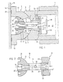
- Fig. 1 denotes a partially shown cylinder, in which a piston 3 is guided in a cylinder bore 2.
- the piston 3 is acted upon by a pressure medium at one end, not shown, while the other end 4 has a concave, spherical zone-shaped sliding surface on the end face, on which a slide shoe 6 with a convex spherical zone-shaped surface 7 is mounted.
- the slide shoe 6 has a cavity 8, which has a radius R1 in its base merging into a concave, spherical zone-shaped surface 9, the center of which 10 lies in the cavity 8.
- the convex, spherical zone-shaped surface 7 of the sliding block 6 with a radius R2 also has the same spherical center 10.
- the wall 12 of the sliding block 6 has a hollow spherical shape which merges into a flange 13, the end face 14 of which forms a sliding surface which is supported on a support surface 15 (not shown in more detail).
- the end face 14 of the slide shoe 6 and the support surface 15 have a relative movement to one another, the support surface 15 being fixed and the end face 14 of the slide shoe 6 rotating or vice versa the support surface 15 rotating and the end face 14 of the slide shoe 6 being stationary, depending on which one It is a type of piston unit. If the cylinder 1 rotates, the end face 14 of the sliding block 6 moves on the stationary support surface 15, as is the case with axial piston units with a rotating cylinder. However, the axial piston unit can also have a stationary cylinder 1, so that in this case the support surface 15 rotates.
- a passage 16 is provided in the wall 12 thereof, through which a coupling member 18 protrudes.
- the coupling member 18 is composed of a shaft part 19 and two joint heads 20, 21 arranged at its ends.
- the head 20 has a spherical shape with a spherical zone-shaped surface 11.
- the head 20 is firmly connected to the shaft part 19, for example by means of a threaded connection.
- the coupling member 18 can also be composed in a different way, as shown in FIG. 2.
- the joint head 20 located in the sliding block 6 is integrally connected to the shaft part 19 and is accordingly a single part.
- the coupling member 18 can also be made in three parts, the two rod ends 20, 21 being firmly connected to the shaft part 19, for example by threaded connections 20 ', 21'.
- the joint head 21 is also formed in two parts, a plate 32 having the concave spherical zone 23 being arranged on the side of the joint head 21 directed against the joint head 20. Since the rod end 21 has no further sliding function, it is sufficient if the plate 32 is made of a material which has particularly favorable sliding properties and high abrasion resistance, e.g. B. from a heat-treated, in particular alloyed steel, from a bronze-coated steel or entirely of bronze. If the joint head 21 and also the joint head 20 consist of one piece, the same considerations apply to the formation of the concave spherical zone 23 and the convex, spherical zone-shaped sliding surface 11 as for the formation of the plate 32.
- a material which has particularly favorable sliding properties and high abrasion resistance e.g. B. from a heat-treated, in particular alloyed steel, from a bronze-coated steel or entirely of bronze.
- the head 21 lies in the interior 22 of the hollow piston 3 and has a cylindrical shape which has the shape of a concave spherical zone on the side 23 facing the sliding shoe 6.
- the spherical zone 23 lies on a convex spherical zone 24 which is arranged at the bottom of the interior 22 of the piston 3.
- the ball zone 24 can, see the lower part of FIG. 1, be formed as an integral part of the piston 3. Or it can, see the upper half of FIG. 1, be produced as a separate part 25 with a flat underside 26 be placed on the in this case flat floor 27 in the interior 22 of the piston 3.
- the radius of curvature R3 of the two spherical zones 23, 24 expediently has the same spherical center 10 as the radii of curvature of the spherical zone-shaped surfaces 5, 7 and 9, 11.
- the entire length of the coupling member 18 is provided with a bore 28 through which the pressure medium located in the interior 22 of the piston 3 is guided into the cavity 8 and from there can be used for the supply of pressure fields 29 in the end face 24.
- a transverse bore 30 is arranged in the shaft part 19. This is connected to the longitudinal bore 28 and enables the introduction of the pressure medium into the passage 17 in the wall 12 of the sliding block 6 and into the bore 31 provided in the bottom of the piston 3. This causes all three sliding surfaces 5, 7; 9, 11 and 23, 25 acted upon by the pressure medium.
Landscapes
- Engineering & Computer Science (AREA)
- General Engineering & Computer Science (AREA)
- Mechanical Engineering (AREA)
- Chemical & Material Sciences (AREA)
- Combustion & Propulsion (AREA)
- Reciprocating Pumps (AREA)
- Pistons, Piston Rings, And Cylinders (AREA)
Priority Applications (1)
| Application Number | Priority Date | Filing Date | Title |
|---|---|---|---|
| AT89104147T ATE99387T1 (de) | 1988-05-10 | 1989-03-09 | Kolbeneinrichtung fuer eine kolbeneinheit. |
Applications Claiming Priority (2)
| Application Number | Priority Date | Filing Date | Title |
|---|---|---|---|
| CH1769/88A CH678091A5 (fr) | 1988-05-10 | 1988-05-10 | |
| CH1769/88 | 1988-05-10 |
Publications (3)
| Publication Number | Publication Date |
|---|---|
| EP0341390A2 true EP0341390A2 (fr) | 1989-11-15 |
| EP0341390A3 EP0341390A3 (en) | 1990-09-05 |
| EP0341390B1 EP0341390B1 (fr) | 1993-12-29 |
Family
ID=4218159
Family Applications (1)
| Application Number | Title | Priority Date | Filing Date |
|---|---|---|---|
| EP89104147A Expired - Lifetime EP0341390B1 (fr) | 1988-05-10 | 1989-03-09 | Dispositif de piston pour une unité de piston |
Country Status (5)
| Country | Link |
|---|---|
| US (1) | US5099750A (fr) |
| EP (1) | EP0341390B1 (fr) |
| AT (1) | ATE99387T1 (fr) |
| CH (1) | CH678091A5 (fr) |
| DE (1) | DE58906516D1 (fr) |
Cited By (2)
| Publication number | Priority date | Publication date | Assignee | Title |
|---|---|---|---|---|
| WO2009103762A1 (fr) * | 2008-02-22 | 2009-08-27 | Polysius Ag | Système de transmission de force avec un cylindre hydraulique et un palier de pression |
| CN105057024A (zh) * | 2015-07-20 | 2015-11-18 | 成都大宏立机器股份有限公司 | 高压辊磨机球头传力机构 |
Families Citing this family (6)
| Publication number | Priority date | Publication date | Assignee | Title |
|---|---|---|---|---|
| US5445030A (en) * | 1993-10-06 | 1995-08-29 | Wyle Laboratories | Spherical coupling |
| US6116990A (en) * | 1997-07-25 | 2000-09-12 | Applied Materials, Inc. | Adjustable low profile gimbal system for chemical mechanical polishing |
| EP1605096B1 (fr) * | 2004-06-11 | 2007-09-05 | Metso Paper, Inc. | Presse à patin |
| US20120240896A1 (en) * | 2011-03-21 | 2012-09-27 | Tadeusz Slawinski | Internal Combustion Engine with Rotating Cylinder Block |
| US11136973B2 (en) | 2018-07-20 | 2021-10-05 | Cole-Parmer Instrument Company Llc | Tubing retention mechanism usable with a peristaltic pump |
| EP4647600A1 (fr) * | 2024-05-10 | 2025-11-12 | Goodrich Actuation Systems SAS | Ensemble piston pour pompe hydraulique |
Family Cites Families (8)
| Publication number | Priority date | Publication date | Assignee | Title |
|---|---|---|---|---|
| DE968651C (de) * | 1940-09-10 | 1958-06-04 | Schlafhorst & Co W | Schiefscheibentriebwerk |
| US2483856A (en) * | 1945-03-08 | 1949-10-04 | Cash A W Co | Hydraulic mechanism |
| US2901979A (en) * | 1953-07-24 | 1959-09-01 | North American Aviation Inc | Hydraulic unit with improved piston assembly |
| US3319575A (en) * | 1965-06-14 | 1967-05-16 | Sundstrand Corp | Piston |
| DE2163158A1 (de) * | 1970-12-19 | 1972-07-13 | Salzmann W | Kurbeltrieb für Hubkolbenmaschinen |
| DE2118712A1 (de) * | 1971-04-17 | 1972-11-16 | Robert Bosch Gmbh, 7000 Stuttgart | Kolben-Gleitschuh-Element für hydrostatische Kolbenmaschinen |
| DE2915239C2 (de) * | 1979-04-14 | 1984-04-26 | Wepuko-Hydraulik GmbH & Co Pumpen- und Kompressorenfabrik, 7418 Metzingen | Radialkolbenpumpe |
| FR2492469B1 (fr) * | 1980-10-28 | 1985-10-31 | Poclain Hydraulics Sa | Ensemble d'un piston pour un mecanisme a fluide a plateau de reaction et de son patin de glissement |
-
1988
- 1988-05-10 CH CH1769/88A patent/CH678091A5/de not_active IP Right Cessation
-
1989
- 1989-03-09 AT AT89104147T patent/ATE99387T1/de active
- 1989-03-09 EP EP89104147A patent/EP0341390B1/fr not_active Expired - Lifetime
- 1989-03-09 DE DE89104147T patent/DE58906516D1/de not_active Expired - Fee Related
-
1990
- 1990-11-13 US US07/614,184 patent/US5099750A/en not_active Expired - Fee Related
Cited By (4)
| Publication number | Priority date | Publication date | Assignee | Title |
|---|---|---|---|---|
| WO2009103762A1 (fr) * | 2008-02-22 | 2009-08-27 | Polysius Ag | Système de transmission de force avec un cylindre hydraulique et un palier de pression |
| JP2011512253A (ja) * | 2008-02-22 | 2011-04-21 | ポリシウス アクチェンゲゼルシャフト | 液圧シリンダ及びスラスト軸受を備える動力伝達システム |
| US8398008B2 (en) | 2008-02-22 | 2013-03-19 | Polysius Ag | Force transfer system comprising a hydraulic cylinder and a thrust bearing |
| CN105057024A (zh) * | 2015-07-20 | 2015-11-18 | 成都大宏立机器股份有限公司 | 高压辊磨机球头传力机构 |
Also Published As
| Publication number | Publication date |
|---|---|
| EP0341390A3 (en) | 1990-09-05 |
| CH678091A5 (fr) | 1991-07-31 |
| EP0341390B1 (fr) | 1993-12-29 |
| DE58906516D1 (de) | 1994-02-10 |
| US5099750A (en) | 1992-03-31 |
| ATE99387T1 (de) | 1994-01-15 |
Similar Documents
| Publication | Publication Date | Title |
|---|---|---|
| DE2620523A1 (de) | Axialkolbenmaschine nach dem schraegscheibenprinzip | |
| DE2106923A1 (de) | Brennkraftmaschinenkolben | |
| DE2305857A1 (de) | Kolben fuer brennkraftmaschinen | |
| DE3136110C2 (de) | Gelenkkupplung | |
| EP0341390B1 (fr) | Dispositif de piston pour une unité de piston | |
| DE3315658C2 (de) | Kugelgelenk, insbesondere Spurstangengelenk | |
| EP0752530B1 (fr) | Machine à piston alternatif et entraínement par plateau oscillant | |
| DD202597A5 (de) | Mechanismus zur umwandlung einer drehbewegung in eine geradlinige hin- und herbewegung | |
| CH666094A5 (de) | Kreuzkopfzapfenlager fuer kolbenmaschinen. | |
| EP1607630A1 (fr) | Compresseur à piston | |
| EP0705968A1 (fr) | Piston pour moteur à combustion | |
| DE882932C (de) | Raeumlich arbeitendes Hubkolbengetriebe | |
| DE3140921A1 (de) | Kolben und gleitschuh umfassende anordnung fuer hydraulische arbeitsgeraete | |
| DE3800031A1 (de) | Axialkolbenmaschine mit drehmomententwicklung an der hubscheibe | |
| DE3206152A1 (de) | Kreuzkopf einer kolbenmaschine | |
| DE2003851A1 (de) | Hydropumpe bzw. -motor der Axialkolbenbauart | |
| DE3039382A1 (de) | Leichter tachkolben fuer verbrennungsmotoren | |
| DE3540085A1 (de) | Kolben fuer brennkraftmaschinen | |
| DE3641783A1 (de) | Zug- und druckkraefte uebertragende gelenkverbindung zwischen einem kolben und einem pleuel | |
| DE2641158A1 (de) | Axialkolbenpumpe | |
| AT380819B (de) | Drehgelenk fuer manipulatoren | |
| DE1653613C3 (de) | Mitnahmevorrichtung für die Pleuelstangen einer Schrägscheiben-Axialkolbenmaschine | |
| EP1287232B1 (fr) | Moteur a piston axial | |
| DE69924287T2 (de) | Pleuel-kolben verbindungseinheit | |
| DE1176954B (de) | Stufenlos regelbare hydrostatische Kraft-uebertragung |
Legal Events
| Date | Code | Title | Description |
|---|---|---|---|
| PUAI | Public reference made under article 153(3) epc to a published international application that has entered the european phase |
Free format text: ORIGINAL CODE: 0009012 |
|
| AK | Designated contracting states |
Kind code of ref document: A2 Designated state(s): AT BE DE ES FR GB GR IT LU NL SE |
|
| PUAL | Search report despatched |
Free format text: ORIGINAL CODE: 0009013 |
|
| AK | Designated contracting states |
Kind code of ref document: A3 Designated state(s): AT BE DE ES FR GB GR IT LU NL SE |
|
| 17P | Request for examination filed |
Effective date: 19910212 |
|
| 17Q | First examination report despatched |
Effective date: 19920703 |
|
| GRAA | (expected) grant |
Free format text: ORIGINAL CODE: 0009210 |
|
| ITF | It: translation for a ep patent filed | ||
| AK | Designated contracting states |
Kind code of ref document: B1 Designated state(s): AT BE DE ES FR GB GR IT LU NL SE |
|
| PG25 | Lapsed in a contracting state [announced via postgrant information from national office to epo] |
Ref country code: NL Effective date: 19931229 Ref country code: GR Free format text: LAPSE BECAUSE OF FAILURE TO SUBMIT A TRANSLATION OF THE DESCRIPTION OR TO PAY THE FEE WITHIN THE PRESCRIBED TIME-LIMIT Effective date: 19931229 Ref country code: ES Free format text: THE PATENT HAS BEEN ANNULLED BY A DECISION OF A NATIONAL AUTHORITY Effective date: 19931229 Ref country code: BE Effective date: 19931229 |
|
| REF | Corresponds to: |
Ref document number: 99387 Country of ref document: AT Date of ref document: 19940115 Kind code of ref document: T |
|
| REF | Corresponds to: |
Ref document number: 58906516 Country of ref document: DE Date of ref document: 19940210 |
|
| ET | Fr: translation filed | ||
| PG25 | Lapsed in a contracting state [announced via postgrant information from national office to epo] |
Ref country code: AT Effective date: 19940309 |
|
| PG25 | Lapsed in a contracting state [announced via postgrant information from national office to epo] |
Ref country code: LU Free format text: LAPSE BECAUSE OF NON-PAYMENT OF DUE FEES Effective date: 19940331 |
|
| GBT | Gb: translation of ep patent filed (gb section 77(6)(a)/1977) |
Effective date: 19940427 |
|
| NLV1 | Nl: lapsed or annulled due to failure to fulfill the requirements of art. 29p and 29m of the patents act | ||
| PLBE | No opposition filed within time limit |
Free format text: ORIGINAL CODE: 0009261 |
|
| STAA | Information on the status of an ep patent application or granted ep patent |
Free format text: STATUS: NO OPPOSITION FILED WITHIN TIME LIMIT |
|
| 26N | No opposition filed | ||
| EAL | Se: european patent in force in sweden |
Ref document number: 89104147.7 |
|
| PGFP | Annual fee paid to national office [announced via postgrant information from national office to epo] |
Ref country code: GB Payment date: 20010214 Year of fee payment: 13 |
|
| PGFP | Annual fee paid to national office [announced via postgrant information from national office to epo] |
Ref country code: SE Payment date: 20010305 Year of fee payment: 13 |
|
| PGFP | Annual fee paid to national office [announced via postgrant information from national office to epo] |
Ref country code: FR Payment date: 20010313 Year of fee payment: 13 Ref country code: DE Payment date: 20010313 Year of fee payment: 13 |
|
| REG | Reference to a national code |
Ref country code: GB Ref legal event code: IF02 |
|
| PG25 | Lapsed in a contracting state [announced via postgrant information from national office to epo] |
Ref country code: GB Free format text: LAPSE BECAUSE OF NON-PAYMENT OF DUE FEES Effective date: 20020309 |
|
| PG25 | Lapsed in a contracting state [announced via postgrant information from national office to epo] |
Ref country code: SE Free format text: LAPSE BECAUSE OF NON-PAYMENT OF DUE FEES Effective date: 20020310 |
|
| PG25 | Lapsed in a contracting state [announced via postgrant information from national office to epo] |
Ref country code: DE Free format text: LAPSE BECAUSE OF NON-PAYMENT OF DUE FEES Effective date: 20021001 |
|
| EUG | Se: european patent has lapsed |
Ref document number: 89104147.7 |
|
| GBPC | Gb: european patent ceased through non-payment of renewal fee |
Effective date: 20020309 |
|
| PG25 | Lapsed in a contracting state [announced via postgrant information from national office to epo] |
Ref country code: FR Free format text: LAPSE BECAUSE OF NON-PAYMENT OF DUE FEES Effective date: 20021129 |
|
| REG | Reference to a national code |
Ref country code: FR Ref legal event code: ST |
|
| PG25 | Lapsed in a contracting state [announced via postgrant information from national office to epo] |
Ref country code: IT Free format text: LAPSE BECAUSE OF NON-PAYMENT OF DUE FEES Effective date: 20050309 |