EP0341410A2 - Outil à main pour préparations alimentaires - Google Patents
Outil à main pour préparations alimentaires Download PDFInfo
- Publication number
- EP0341410A2 EP0341410A2 EP89105377A EP89105377A EP0341410A2 EP 0341410 A2 EP0341410 A2 EP 0341410A2 EP 89105377 A EP89105377 A EP 89105377A EP 89105377 A EP89105377 A EP 89105377A EP 0341410 A2 EP0341410 A2 EP 0341410A2
- Authority
- EP
- European Patent Office
- Prior art keywords
- housing
- hand mixer
- handle
- mixer according
- air
- Prior art date
- Legal status (The legal status is an assumption and is not a legal conclusion. Google has not performed a legal analysis and makes no representation as to the accuracy of the status listed.)
- Granted
Links
Images

Classifications
-
- A—HUMAN NECESSITIES
- A47—FURNITURE; DOMESTIC ARTICLES OR APPLIANCES; COFFEE MILLS; SPICE MILLS; SUCTION CLEANERS IN GENERAL
- A47J—KITCHEN EQUIPMENT; COFFEE MILLS; SPICE MILLS; APPARATUS FOR MAKING BEVERAGES
- A47J43/00—Implements for preparing or holding food, not provided for in other groups of this subclass
- A47J43/04—Machines for domestic use not covered elsewhere, e.g. for grinding, mixing, stirring, kneading, emulsifying, whipping or beating foodstuffs, e.g. power-driven
- A47J43/044—Machines for domestic use not covered elsewhere, e.g. for grinding, mixing, stirring, kneading, emulsifying, whipping or beating foodstuffs, e.g. power-driven with tools driven from the top side
-
- A—HUMAN NECESSITIES
- A47—FURNITURE; DOMESTIC ARTICLES OR APPLIANCES; COFFEE MILLS; SPICE MILLS; SUCTION CLEANERS IN GENERAL
- A47J—KITCHEN EQUIPMENT; COFFEE MILLS; SPICE MILLS; APPARATUS FOR MAKING BEVERAGES
- A47J43/00—Implements for preparing or holding food, not provided for in other groups of this subclass
- A47J43/04—Machines for domestic use not covered elsewhere, e.g. for grinding, mixing, stirring, kneading, emulsifying, whipping or beating foodstuffs, e.g. power-driven
- A47J43/07—Parts or details, e.g. mixing tools, whipping tools
- A47J43/08—Driving mechanisms
- A47J43/082—Driving mechanisms for machines with tools driven from the upper side
-
- A—HUMAN NECESSITIES
- A47—FURNITURE; DOMESTIC ARTICLES OR APPLIANCES; COFFEE MILLS; SPICE MILLS; SUCTION CLEANERS IN GENERAL
- A47J—KITCHEN EQUIPMENT; COFFEE MILLS; SPICE MILLS; APPARATUS FOR MAKING BEVERAGES
- A47J43/00—Implements for preparing or holding food, not provided for in other groups of this subclass
- A47J43/04—Machines for domestic use not covered elsewhere, e.g. for grinding, mixing, stirring, kneading, emulsifying, whipping or beating foodstuffs, e.g. power-driven
- A47J43/044—Machines for domestic use not covered elsewhere, e.g. for grinding, mixing, stirring, kneading, emulsifying, whipping or beating foodstuffs, e.g. power-driven with tools driven from the top side
- A47J2043/04409—Apparatus of hand held type
- A47J2043/04418—Apparatus of hand held type with housing extending perpendicular, e.g. horizontally, from the tool axis
-
- Y—GENERAL TAGGING OF NEW TECHNOLOGICAL DEVELOPMENTS; GENERAL TAGGING OF CROSS-SECTIONAL TECHNOLOGIES SPANNING OVER SEVERAL SECTIONS OF THE IPC; TECHNICAL SUBJECTS COVERED BY FORMER USPC CROSS-REFERENCE ART COLLECTIONS [XRACs] AND DIGESTS
- Y10—TECHNICAL SUBJECTS COVERED BY FORMER USPC
- Y10S—TECHNICAL SUBJECTS COVERED BY FORMER USPC CROSS-REFERENCE ART COLLECTIONS [XRACs] AND DIGESTS
- Y10S366/00—Agitating
- Y10S366/601—Motor control
Definitions
- the invention relates to a hand mixer for processing food, with a motor, a gear and a receiving device connected to the gear for fastening work tools housing, from which a handle for holding the hand mixer extends sideways, for cooling the motor on the housing Air slots are provided to ensure that the cooling air flows through the housing.
- Such hand mixers are not only suitable for stirring, kneading, whipping, but also for crushing food.
- hand mixers ("Krups 3 Mix 4000” from the brochure "The Current Program '88 of the Robert Krups Foundation & Co., Solingen, page 16-19) are known, which attach a horizontal, parallel to the housing or on the device body Handle and which are provided on the underside of the body of the device with openings for inserting the kneading and stirring inserts.
- the comminution rod must be driven on the back of the device for technical reasons, apart from the fact that already when using kneading and stirring inserts at normal high work table with a strongly angled arm, the device cannot be handled in the position tilted by 90 ° for the shredding rod without an additional, unfavorable position of the wrist or arm.
- the arrangement of a total of two insertion points for the working tools is unfavorable due to the different speeds required, especially since the insertion point for the shredding rod is located in the rear louvre area of the device.
- This has the disadvantage when the device is parked on the storage surface that the shredding rod then points vertically upwards and foodstuffs remaining on the shredding rod can penetrate into the motor housing. If the device is put down, the work table becomes dirty.
- the air slots required for cooling are too close to the work tools and thus too close to the foodstuffs to be processed, so that the foodstuffs can take on the smell of the engine vapors emerging from the housing. Contamination of the motor of the hand mixer by dirty cooling air is also possible.
- This device also has the disadvantage that, due to the housing running perpendicularly to the work tools, it obscures the filling opening of the container in which the food is processed, so that the view into the container is obstructed.
- Such a hand mixer is already known from brochure No. 362100 r 5, from Gottlob Widmann + Söhne KG, Schwenningen (Neckar), in which all inserts for stirring, kneading, crushing, beating, emulsifying etc. are from the same side, namely the underside of the device are driven, the drive motor and the gearbox, the latter, among other things, also being used to hold the working tools, being arranged one behind the other and in a narrow space vertically one above the other in the operation of the hand mixer in a more or less cylindrical housing.
- an elongated handle is provided which extends approximately radially outward from the center of the housing substantially perpendicular to its longitudinal axis. Between the engine and gearbox, i.e. in the vicinity of the work tool, there are air slots on the housing for the supply and removal of cooling air.
- louvers near the work tools, which are thus also in the immediate vicinity of the food to be processed, leads to the disadvantage that the particles, such as flour, which are whirled up by the work tools, for example during the processing of dough, are transferred from the fan of the motor the air slots are sucked in and so dirty the engine. This contamination can lead to premature failure of the hand mixer.
- a further disadvantage is that the blower air stream emerging from the blower of the hand mixer can be directed into the mixing bowl even when the hand mixer is at a slight incline or in the case of particularly high bowls.
- the flour in the mixing bowl is thereby whirled up and can be sucked into the housing by the fan wheel via the suction slots, which can also lead to the disadvantages already described above.
- the object of the invention is therefore to develop the known hand mixers so that the handle, which is in and of itself necessary, not only serves to hold and guide the device, but also takes on other functions which improve the manageability and / or reduce the through Risk of pollution caused by cooling air.
- This object is achieved in that at least one air duct is formed in the handle, in which the cooling air is guided from the outside to the housing and / or away from the housing.
- This inventive arrangement of the air duct in the handle completely prevents the cooling air required during operation of the hand mixer from being directed at the foodstuffs to be processed. This also occurs when the hand mixer is held at a slight angle.
- the cooling air By supplying and / or discharging the cooling air radially outward, away from the device or radially from the outside to the device, on the one hand whirling up, for example of flour, is avoided by the cooling air and, at the same time, whirled-up flour, which also occurs during mixing, for example cannot be sucked in by the hand mixer. Because the cooling air emitted from the housing of the hand mixer, which in many cases has taken on the unpleasant smell of the machine parts of the hand mixer, does not affect the food, the taste of the food does not change adversely.
- the arrangement according to the invention thus enables for the first time that no cooling air required for the hand mixer is flowing in the vicinity of the food, nor is it sucked in by it.
- the cooling air is kept as far as possible from the work tools processing the food, such as dough hooks, whisks, etc.
- air inlet and / or Air outlet openings are provided in the form of air slots, which form the beginning or the end of the air duct.
- the handle can therefore be used both as a supply of cold air and as a discharge of the air that has already been heated by the engine.
- the design of the handle both as an inlet and as an outlet channel is also possible by means of a partition.
- the air slots lead the air flow transversely to the direction of the working tool and possibly still slightly upwards out of the hand mixer, so that even with possible inclined positions of the hand mixer it is always ensured that the air flow does not enter the container holding the food flow into which the working tools protrude and the food is processed.
- an extension element is formed at the free end of the handle which extends essentially parallel to the longitudinal axis of the housing and the working tool and on which the louvers are provided on the side facing away from the housing.
- the attachment element according to the invention can, for example, be molded directly onto the handle or also flanged onto it.
- this extension element has the further advantage that if the center of gravity of the hand mixer falls approximately centrally on the extension element, this extension element simultaneously serves as a foot for parking the manual mixer. This has the further advantage that when the stirring process is briefly interrupted, the work tools do not come into contact with the work surface and do not contaminate them unnecessarily.
- the handle is formed on the upper area of the housing opposite the working tool and is directed obliquely downwards.
- the handle which acts obliquely on the housing of the hand mixer, makes it easy to position the wrist and the upper and lower arm with as little effort as possible.
- the holding forces are therefore predominantly taken over by the muscular and long-lasting upper arm, while the wrist is supported in the longitudinal direction of the forearm on the joint stop and there are therefore no significant holding forces on the wrist.
- the inclination of the handle to the longitudinal axis of the housing must be chosen so that the wrist is supported on its lower joint stop.
- An angle of 60 ° to 75 ° preferably 68 ° , has proven to be particularly advantageous.
- the inclined handle arrangement has the further advantage that, if no attachment element is arranged on the handle, it is still possible to switch off the hand mixer with a brief interruption by hanging the hand mixer between the handle and the housing on the edge of a stirred tank. In the case of particularly narrow transitions between the handle and the housing, the hand mixer can even be clamped in at the edge of the lid.
- an arm extending substantially perpendicular to the longitudinal axis of the housing is provided on the lower region of the housing which is closer to the working tool and that the arm for Cooling of the engine is provided with another air duct.
- This additional arm makes it possible to introduce the air into the housing from above using the handle and to discharge it again at the lower end via the arm.
- the cooling air is guided through the housing in only one direction, thereby avoiding complex return channels which are required when the cooling air has to be returned to the handle in the housing.
- Optimal cooling is achieved by the cooling air flowing around the motor.
- a particularly simple manufacture of the housing parts is achieved in that the arm is connected to the handle via the attachment element and that both air slots for the entry and exit of the air from the air guide channels are formed on the attachment element.
- the connection of the arm via the extension element to the handle ensures a particularly rigid, stable housing arrangement.
- the air slots are separated from one another by a web on the attachment element.
- the arm In order for the overall length of the housing and thus the hand mixer to be as compact as possible, the arm also serves to accommodate the gear unit or a part thereof. This results in the possibility of accommodating parts of the transmission devices that would otherwise also be arranged in the engine area in this arm. If necessary, the arm can be provided with an extension at its transition to the housing. As a result, the dimensions of the hand mixer can be made much smaller than is the case with conventional devices.
- a recess for receiving and guiding a connecting cable joint is provided in the upper part of the extension element, which is sealed with respect to the air duct, the pivoting direction of the connecting joint being longitudinal of the handle. Due to this advantageous design, the hand mixer can be used by both left and right-handers, since the connecting cable is no longer arranged on the side of the hand mixer.
- connection cable Due to the pivotable arrangement of the connection cable, this can be pivoted parallel to the storage surface when the hand mixer is parked, so that it does not interfere with the storage surface.
- the connection cable joint is sealed against the air duct so that the air only flows in and out through the air slots. This avoids disturbing air noises and external inlets from the outset.
- air slots also extend into the side surfaces of the attachment element. These then allow the cooling air to be discharged or fed in laterally while the device is still running. A discharge or supply of the cooling air when the hand mixer is parked on the shelf is also ensured by the fact that raised foot elements are formed on the shelf.
- the arm on the underside of the arm there is a tongue which can be displaced transversely to the working tools and by means of which tongue at least one insertion opening and the receiving device connected to it can be closed.
- the arm therefore not only serves as an air duct or as a receptacle for gear parts, but at the same time enables the inclusion of a closing device for at least one insertion opening receiving a working tool when it is not required.
- a further development of the invention proposes that a groove is formed on the radially outer circumference of the attachment element.
- the connecting cable can therefore be wound around the channel without problems, without it sliding off the device and then being a hindrance when the hand mixer is parked over its storage surface.
- the motor and the working tool are arranged one behind the other in the longitudinal direction of the housing, that the free end of the handle has a storage surface facing away from the housing, which is essentially parallel to the longitudinal axis of the housing and that the storage area is dimensioned such that parking the hand mixer on the storage surface hits the storage surface perpendicular to the level of the storage surface of the center of gravity emanating from the hand mixer.
- the handle which is already used, for example, to hold electronic components, such as an on / off switch or the electronic control for the motor, is now additionally used as a stand according to the invention.
- an arm extends radially outward from the end closer to the work tools from the housing and that the free end of the arm has a storage surface facing away from the housing, which lies in the plane of the storage surface of the handle.
- the arm arranged on the housing can also be used as an additional handle for particularly tough doughs.
- a further enlargement of the storage area is achieved in that the free ends of the handle and the arm are connected to one another by an attachment element and in that a storage area is formed on the attachment element which is in contact with the storage areas of the handle and the arm form a common level.
- the housing-side connection of the handle to the arm via the extension element increases the rigidity of the hand mixer, so that any vibrations in the housing caused by the motor are largely reduced or dampened.
- the maneuverability of the device is particularly improved in that the handle forms with the longitudinal axis o of the housing at an angle of 60 to 75 o.
- an angle of 68 o has proven to be optimal.
- the motor and the working tool are arranged one behind the other in the longitudinal direction, if an air duct for the supply or discharge of the cooling air is formed in the handle if another air duct for the supply or discharge of the arm Cooling air is provided and when the two parts are connected to one another via an attachment element, which forms a storage surface for the hand mixer with them.
- a hand mixer avoids all of the disadvantages described above.
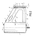
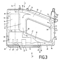
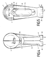
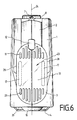
- FIGS 1 to 6 show the hand mixer according to the invention, which is used for crushing, kneading and stirring, etc.
- an elongated handle 2 which can be comfortably enclosed by one hand, is arranged transversely to the housing 1 and obliquely downwards molded.
- the surface of the handle 2 merges into the surface of the housing 1 in a highly rounded manner.
- the hand mixer can already be advantageously stored on the mixing container (not shown), which is often provided with a rounded collar.
- recessed grips 6 for the thumb and forefinger are formed on both sides in the rounded surface of the handle 2 (FIGS. 1 and 2).
- a step switch 7 which can be displaced transversely to its longitudinal direction is provided according to FIGS. 1 to 6.
- an eject button 8 protrudes, and when it is actuated, the respective work tool 5 protrudes its receiving device 21 arranged on the transmission 20 is unlocked and falls out of the hand mixer via the corresponding insertion opening 13, 14.
- the plug-in openings 13, 14 for the various work tools 5, which are connected to the latching means (not shown in detail), are located in a raised portion 4, preferably framed, on the underside of the housing.
- the motor 19 and the work tools 5 in the same longitudinal axis 24 of the housing 1, so that complex angular gears are avoided.
- the transmission 20 is arranged between the motor 19 and the work tools 5 in the housing 1.
- the hand mixer can be conveniently and securely placed on a work surface 23, not shown, on a support surface 23 which is formed on the free end of the handle 2 and extends parallel to the longitudinal axis 24 of the bone body.
- a work surface 23 which is formed on the free end of the handle 2 and extends parallel to the longitudinal axis 24 of the bone body.
- the storage surface 23 facing away from the housing body 1 of the rounded top and bottom extension element 3 is therefore formed in Fig. 1 as an enlarged footprint of the handle and also allows the hand mixer equipped with work tools 5 to be set up without these work tools 5 touching the work surface of the table, but instead even run parallel to the work surface.
- the focus, stable position of the hand mixer is facilitated by the oblique approach (defined by angle b) of the handle 2.
- the hand mixer shown in FIG. 1 is extended by an arm 10 connecting the lower region of the housing 1 to the attachment element 3.
- This arm 10 runs essentially perpendicular to the housing 1 and radially outwards the extension element 3, the adjoining handle 2 and the housing 1 a homogeneous and stable plastic housing surface, the laterally rounded and flat at the top and bottom arm 10 (FIGS. 2 and 3) tapering from the housing body 1 to the extension element 3.
- the transition area from the housing body 1 to the arm 10 thus represents an extension 27 in order to partially position parts of the transmission 20 there.
- the hand mixer shown in FIGS. 2-6 has increased stability due to the arm producing a closed housing unit with attachment element 3 and handle 2.
- the unit shown is made as a plastic shell housing from at least two parts.
- a space-saving DC motor is used as the motor 19, so that the cross section and the axial overall length (also due to the inclusion of gear parts in the extension 27) of the device body 1 are considerably reduced overall. 6, the louvers 11, 26 are separated from one another by the web 31.
- the flat underside 29 of the arm 10, which runs perpendicular to the storage surface 23, has a protruding and flush with the section 4, elongated, raised tongue 16, which has approximately the same height as the section 4 and which extends in the longitudinal direction of the arm 10 (Figs. 3, 5 and 6).
- the edge areas 39 of both sections 4, 16 are folded apart from one another in the transition area 40 of the sections 4, 16.
- the section 4 is adapted to the outer surface of the housing 1 and has a slightly smaller diameter than this. Where the cylindrical housing 1 merges into the arm 10, the section 4 has a trailing edge 40.
- the front end edge 15 of the tongue 16 adjoins this end edge 40 when the tongue 16 closes the bore 14.
- the elongated tongue 16, rounded at both ends, is displaceable against the spring force B of a spring device (not shown) (FIG. 5).
- the open position of the tongue 16 is shown by the bore 14 for receiving a blender rod, not shown, is exposed by this. If, for example, the blender is removed when the eject button 8 is pressed, the tongue 16 automatically pushes back into the above-mentioned closed position by spring force and covers the insertion opening 14, which is particularly important when using the other working tools 5 (2 dough hooks or 2 whisks) inserted in the front, round area of section 4 in the usual way side by side insertion openings 13 and locked there via the receiving devices 21.
- the insertion openings 13 thus serve to receive two kneading hooks, whisks, etc.
- These work tools 5 are also removed, as in the case of the blender, via the eject button 8.
- the spacer webs 17, which are indicated by the dashed lines and are designed as foot elements, can be placed on both sides in the area between the air slots 11, 26 of the footprint 23, can be provided.
- a trough 41 or recess in the extension element 3 and the adjoining handle 2 is provided, in which a tilt joint 12 for a connecting cable 9 is arranged.
- the connecting cable 9, which can come out of the storage surface 23 when the hand mixer is in operation (FIG. 3), can be folded upwards in the trough 41 to place the hand mixer on it, which is indicated by the pivoting direction 36 according to FIG. 3 is indicated.
- an indentation 18 is formed in the front region of the handle 2 at the transition into the essentially circular top of the housing body 1, from which the tap changer 7 protrudes to such an extent that its top, which is adapted to the inclination of the handle 2, approximately is aligned with the top. In this way, the tap changer 7 no longer protrudes upwards from the handle area, but rather lies in the rounded indentation 18.
- a groove 33 is provided at the free end of the handle and arm 10 in the transition area to the extension element 3 for receiving the connecting cable 9 when the hand mixer is no longer used and is to be placed on the storage surface 23. For this purpose, only the cable needs to be wrapped around the groove 33.
Landscapes
- Engineering & Computer Science (AREA)
- Mechanical Engineering (AREA)
- Food Science & Technology (AREA)
- Food-Manufacturing Devices (AREA)
- Mixers Of The Rotary Stirring Type (AREA)
- Preparation Of Fruits And Vegetables (AREA)
- General Preparation And Processing Of Foods (AREA)
Priority Applications (1)
| Application Number | Priority Date | Filing Date | Title |
|---|---|---|---|
| AT89105377T ATE81955T1 (de) | 1988-05-04 | 1989-03-25 | Handruehrgeraet zum bearbeiten von nahrungsmitteln. |
Applications Claiming Priority (2)
| Application Number | Priority Date | Filing Date | Title |
|---|---|---|---|
| DE3815177 | 1988-05-04 | ||
| DE3815177A DE3815177C1 (fr) | 1988-05-04 | 1988-05-04 |
Publications (3)
| Publication Number | Publication Date |
|---|---|
| EP0341410A2 true EP0341410A2 (fr) | 1989-11-15 |
| EP0341410A3 EP0341410A3 (en) | 1990-03-28 |
| EP0341410B1 EP0341410B1 (fr) | 1992-11-04 |
Family
ID=6353607
Family Applications (1)
| Application Number | Title | Priority Date | Filing Date |
|---|---|---|---|
| EP89105377A Expired - Lifetime EP0341410B1 (fr) | 1988-05-04 | 1989-03-25 | Outil à main pour préparations alimentaires |
Country Status (5)
| Country | Link |
|---|---|
| US (1) | US4922464A (fr) |
| EP (1) | EP0341410B1 (fr) |
| AT (1) | ATE81955T1 (fr) |
| CA (1) | CA1301744C (fr) |
| DE (2) | DE3815177C1 (fr) |
Cited By (5)
| Publication number | Priority date | Publication date | Assignee | Title |
|---|---|---|---|---|
| FR2656208A1 (fr) * | 1989-12-22 | 1991-06-28 | Bosch Siemens Hausgeraete | Batteur-mixeur electrique a main. |
| EP0678268A1 (fr) * | 1994-04-23 | 1995-10-25 | Braun Aktiengesellschaft | Appareil manuel et électrique de traitement d'aliments |
| WO2022112800A1 (fr) * | 2020-11-30 | 2022-06-02 | Kenwood Limited | Appareil électrique |
| GB2602785A (en) * | 2020-11-30 | 2022-07-20 | Kenwood Ltd | Electrical appliance |
| GB2602052B (en) * | 2020-12-16 | 2025-04-02 | Kenwood Ltd | Electrical appliance |
Families Citing this family (8)
| Publication number | Priority date | Publication date | Assignee | Title |
|---|---|---|---|---|
| US5384725A (en) * | 1990-05-18 | 1995-01-24 | Yale University | Method and apparatus for encoding and decoding using wavelet-packets |
| DE19645309A1 (de) * | 1996-11-04 | 1998-05-07 | Braun Ag | Küchenmaschine |
| USD430774S (en) * | 1999-01-06 | 2000-09-12 | Hp Intellectual Corp. | Hand mixer |
| DE10243121A1 (de) * | 2002-09-18 | 2004-04-01 | Braun Gmbh | Handrührer zum Bearbeiten von Nahrungsmitteln |
| FR2987942B1 (fr) * | 2012-03-12 | 2014-05-16 | Hameur Sa | Appareil portatif comportant un cable electrique |
| US9848737B2 (en) | 2014-10-24 | 2017-12-26 | Sunbeam Products, Inc. | Appliance with recessed handle and cooling air inlets |
| US20250031906A1 (en) * | 2023-07-24 | 2025-01-30 | Whirlpool Corporation | Cord holder for a kitchen appliance |
| DE102024114087A1 (de) * | 2024-05-21 | 2025-11-27 | Zwilling J. A. Henckels Aktiengesellschaft | Handrührgerät |
Family Cites Families (13)
| Publication number | Priority date | Publication date | Assignee | Title |
|---|---|---|---|---|
| US2987636A (en) * | 1953-07-09 | 1961-06-06 | Sunbeam Corp | Electric mixer |
| FR1282717A (fr) * | 1960-12-16 | 1962-01-27 | Expl Chimie Et Mecanique E C E | Appareil électro-ménager du genre batteur |
| US3533715A (en) * | 1968-07-31 | 1970-10-13 | Iona Mfg Co Inc | Beater piloting arrangement for an electric food mixer |
| JPS5186807A (fr) * | 1975-01-28 | 1976-07-29 | Toyota Motor Co Ltd | |
| US4032261A (en) * | 1976-05-13 | 1977-06-28 | General Electric Company | Bearing strap and cooler |
| DE2854860C2 (de) * | 1978-12-19 | 1983-03-10 | Siemens AG, 1000 Berlin und 8000 München | Elektroquirl |
| DE8232415U1 (de) * | 1982-11-19 | 1983-03-17 | Robert Krups Stiftung & Co KG, 5650 Solingen | Mehrzweckkuechenmaschine |
| DE3446911A1 (de) * | 1984-12-21 | 1986-07-03 | Bosch-Siemens Hausgeräte GmbH, 7000 Stuttgart | Elektrisches handgeraet zum ruehren und/oder schneiden |
| DE3446859A1 (de) * | 1984-12-21 | 1986-07-03 | Bosch-Siemens Hausgeräte GmbH, 7000 Stuttgart | Elektrisches handgeraet zum ruehren und/oder schneiden |
| DE3447741A1 (de) * | 1984-12-21 | 1986-06-26 | Bosch-Siemens Hausgeräte GmbH, 7000 Stuttgart | Elektrisches handgeraet zum ruehren und/oder schneiden |
| US4620796A (en) * | 1985-01-09 | 1986-11-04 | Black & Decker, Inc. | Electric mixer with beater eject mechanism |
| DE8535646U1 (de) * | 1985-12-18 | 1987-04-16 | Bosch-Siemens Hausgeräte GmbH, 8000 München | Antriebseinheit einer Küchenmaschine |
| DE8613192U1 (de) * | 1986-05-15 | 1987-09-17 | Licentia Patent-Verwaltungs-Gmbh, 6000 Frankfurt | Handrührgerät |
-
1988
- 1988-05-04 DE DE3815177A patent/DE3815177C1/de not_active Expired
-
1989
- 1989-03-25 DE DE8989105377T patent/DE58902595D1/de not_active Expired - Fee Related
- 1989-03-25 AT AT89105377T patent/ATE81955T1/de not_active IP Right Cessation
- 1989-03-25 EP EP89105377A patent/EP0341410B1/fr not_active Expired - Lifetime
- 1989-04-06 CA CA000595941A patent/CA1301744C/fr not_active Expired - Fee Related
- 1989-04-06 US US07/334,682 patent/US4922464A/en not_active Expired - Fee Related
Cited By (8)
| Publication number | Priority date | Publication date | Assignee | Title |
|---|---|---|---|---|
| FR2656208A1 (fr) * | 1989-12-22 | 1991-06-28 | Bosch Siemens Hausgeraete | Batteur-mixeur electrique a main. |
| EP0678268A1 (fr) * | 1994-04-23 | 1995-10-25 | Braun Aktiengesellschaft | Appareil manuel et électrique de traitement d'aliments |
| DE4414230A1 (de) * | 1994-04-23 | 1995-10-26 | Braun Ag | Elektrisch betriebenes Handrührgerät zum Bearbeiten von Nahrungsmitteln |
| US5522659A (en) * | 1994-04-23 | 1996-06-04 | Braun Aktiengesellschaft | Electrically operated hand mixer with a winding arrangement for a connecting cable |
| WO2022112800A1 (fr) * | 2020-11-30 | 2022-06-02 | Kenwood Limited | Appareil électrique |
| GB2602785A (en) * | 2020-11-30 | 2022-07-20 | Kenwood Ltd | Electrical appliance |
| GB2602785B (en) * | 2020-11-30 | 2024-12-04 | Kenwood Ltd | Electrical appliance |
| GB2602052B (en) * | 2020-12-16 | 2025-04-02 | Kenwood Ltd | Electrical appliance |
Also Published As
| Publication number | Publication date |
|---|---|
| CA1301744C (fr) | 1992-05-26 |
| DE3815177C1 (fr) | 1989-09-28 |
| US4922464B1 (fr) | 1993-02-02 |
| US4922464A (en) | 1990-05-01 |
| EP0341410B1 (fr) | 1992-11-04 |
| DE58902595D1 (de) | 1992-12-10 |
| ATE81955T1 (de) | 1992-11-15 |
| EP0341410A3 (en) | 1990-03-28 |
Similar Documents
| Publication | Publication Date | Title |
|---|---|---|
| DE3408692C2 (fr) | ||
| DE69422658T2 (de) | Gerät zum Zubereiten von Teigwaren, Gebäck, Keksen und Vorgerichten | |
| EP0341410B1 (fr) | Outil à main pour préparations alimentaires | |
| EP3250097B1 (fr) | Verrouillage d'outil mélangeur pour robot ménager | |
| EP0529266B1 (fr) | Batteur à main électrique | |
| EP0664975A1 (fr) | Appareil pour le nettoyage de tête de coup des rasoir électriques | |
| DE3015753A1 (de) | Haushaltsmischgeraet fuer nahrungsmittel u.dgl. | |
| DE202010014783U1 (de) | Handbetätigbare Rührmaschine | |
| DE3249220T1 (de) | Elektrische Küchenmaschine | |
| EP0678268A1 (fr) | Appareil manuel et électrique de traitement d'aliments | |
| DE4216335A1 (de) | Zerkleinerungs- und Mischeinrichtung für eine Vielzweckküchenmaschine | |
| EP3536204B1 (fr) | Mélangeur à main commutable entre une durée d'opération courte et longue selon l'outil attaché | |
| EP0156137B1 (fr) | Appareil électrique pour le traitement d'aliments | |
| DE2852532B2 (de) | Haushaltsmaschinen zum Herstellen und Ausformen von Teigwaren | |
| DE3844536A1 (de) | Handruehrgeraet zum bearbeiten von nahrungsmitteln | |
| DE29512854U1 (de) | Drehmesser mit Absaugung für Fleisch oder Fett | |
| DE4440566C1 (de) | Handbetätigbare Rührmaschine | |
| EP0137136A2 (fr) | Instrument pour machine domestique, spécialement pour ustensiles de cuisine | |
| DE4119328A1 (de) | Elektrisch betriebenes mixgeraet | |
| DE3404249A1 (de) | Vielzweckkuechenmaschine mit arbeitsbehaelter | |
| DE69404633T2 (de) | Mixgerät für lebensmittel | |
| DE8613192U1 (de) | Handrührgerät | |
| DE2845689C3 (de) | Schneidgerät zum Zerkleinern von Nahrungsmitteln, wie Fleisch, Zwiebel, Gemüse o.dgl. | |
| DE102007038371A1 (de) | System zum Lagern der Antriebswelle einer Küchenmaschine | |
| DE3144438A1 (de) | Kuechenmaschine mit motorischem antrieb |
Legal Events
| Date | Code | Title | Description |
|---|---|---|---|
| PUAI | Public reference made under article 153(3) epc to a published international application that has entered the european phase |
Free format text: ORIGINAL CODE: 0009012 |
|
| AK | Designated contracting states |
Kind code of ref document: A2 Designated state(s): AT CH DE ES FR GB IT LI NL SE |
|
| PUAL | Search report despatched |
Free format text: ORIGINAL CODE: 0009013 |
|
| AK | Designated contracting states |
Kind code of ref document: A3 Designated state(s): AT CH DE ES FR GB IT LI NL SE |
|
| 17P | Request for examination filed |
Effective date: 19900421 |
|
| 17Q | First examination report despatched |
Effective date: 19910226 |
|
| ITF | It: translation for a ep patent filed | ||
| GRAA | (expected) grant |
Free format text: ORIGINAL CODE: 0009210 |
|
| AK | Designated contracting states |
Kind code of ref document: B1 Designated state(s): AT CH DE ES FR GB IT LI NL SE |
|
| PG25 | Lapsed in a contracting state [announced via postgrant information from national office to epo] |
Ref country code: SE Effective date: 19921104 Ref country code: ES Free format text: THE PATENT HAS BEEN ANNULLED BY A DECISION OF A NATIONAL AUTHORITY Effective date: 19921104 |
|
| REF | Corresponds to: |
Ref document number: 81955 Country of ref document: AT Date of ref document: 19921115 Kind code of ref document: T |
|
| GBT | Gb: translation of ep patent filed (gb section 77(6)(a)/1977) | ||
| REF | Corresponds to: |
Ref document number: 58902595 Country of ref document: DE Date of ref document: 19921210 |
|
| ET | Fr: translation filed | ||
| PLBI | Opposition filed |
Free format text: ORIGINAL CODE: 0009260 |
|
| 26 | Opposition filed |
Opponent name: BOSCH-SIEMENS HAUSGERAETE GMBH, MUENCHEN Effective date: 19930802 |
|
| NLR1 | Nl: opposition has been filed with the epo |
Opponent name: BOSCH-SIEMENS HAUSGERAETE GMBH |
|
| REG | Reference to a national code |
Ref country code: CH Ref legal event code: PFA Free format text: BRAUN AKTIENGESELLSCHAFT |
|
| PGFP | Annual fee paid to national office [announced via postgrant information from national office to epo] |
Ref country code: GB Payment date: 19950224 Year of fee payment: 7 |
|
| PGFP | Annual fee paid to national office [announced via postgrant information from national office to epo] |
Ref country code: AT Payment date: 19950309 Year of fee payment: 7 |
|
| PGFP | Annual fee paid to national office [announced via postgrant information from national office to epo] |
Ref country code: NL Payment date: 19950331 Year of fee payment: 7 |
|
| PGFP | Annual fee paid to national office [announced via postgrant information from national office to epo] |
Ref country code: CH Payment date: 19950505 Year of fee payment: 7 |
|
| RAP2 | Party data changed (patent owner data changed or rights of a patent transferred) |
Owner name: BRAUN AKTIENGESELLSCHAFT |
|
| REG | Reference to a national code |
Ref country code: CH Ref legal event code: PFA Free format text: BRAUN AKTIENGESELLSCHAFT TRANSFER- BRAUN AKTIENGESELLSCHAFT |
|
| NLT2 | Nl: modifications (of names), taken from the european patent patent bulletin |
Owner name: BRAUN AKTIENGESELLSCHAFT |
|
| PG25 | Lapsed in a contracting state [announced via postgrant information from national office to epo] |
Ref country code: GB Effective date: 19960325 Ref country code: AT Effective date: 19960325 |
|
| PG25 | Lapsed in a contracting state [announced via postgrant information from national office to epo] |
Ref country code: LI Effective date: 19960331 Ref country code: CH Effective date: 19960331 |
|
| APAC | Appeal dossier modified |
Free format text: ORIGINAL CODE: EPIDOS NOAPO |
|
| PLBN | Opposition rejected |
Free format text: ORIGINAL CODE: 0009273 |
|
| STAA | Information on the status of an ep patent application or granted ep patent |
Free format text: STATUS: OPPOSITION REJECTED |
|
| PG25 | Lapsed in a contracting state [announced via postgrant information from national office to epo] |
Ref country code: NL Effective date: 19961001 |
|
| 27O | Opposition rejected |
Effective date: 19960730 |
|
| GBPC | Gb: european patent ceased through non-payment of renewal fee |
Effective date: 19960325 |
|
| REG | Reference to a national code |
Ref country code: CH Ref legal event code: PL |
|
| NLV4 | Nl: lapsed or anulled due to non-payment of the annual fee |
Effective date: 19961001 |
|
| PGFP | Annual fee paid to national office [announced via postgrant information from national office to epo] |
Ref country code: FR Payment date: 19980319 Year of fee payment: 10 |
|
| PG25 | Lapsed in a contracting state [announced via postgrant information from national office to epo] |
Ref country code: FR Free format text: LAPSE BECAUSE OF NON-PAYMENT OF DUE FEES Effective date: 19991130 |
|
| REG | Reference to a national code |
Ref country code: FR Ref legal event code: ST |
|
| PGFP | Annual fee paid to national office [announced via postgrant information from national office to epo] |
Ref country code: DE Payment date: 20020306 Year of fee payment: 14 |
|
| PG25 | Lapsed in a contracting state [announced via postgrant information from national office to epo] |
Ref country code: DE Free format text: LAPSE BECAUSE OF NON-PAYMENT OF DUE FEES Effective date: 20031001 |
|
| PG25 | Lapsed in a contracting state [announced via postgrant information from national office to epo] |
Ref country code: IT Free format text: LAPSE BECAUSE OF NON-PAYMENT OF DUE FEES;WARNING: LAPSES OF ITALIAN PATENTS WITH EFFECTIVE DATE BEFORE 2007 MAY HAVE OCCURRED AT ANY TIME BEFORE 2007. THE CORRECT EFFECTIVE DATE MAY BE DIFFERENT FROM THE ONE RECORDED. Effective date: 20050325 |
|
| APAH | Appeal reference modified |
Free format text: ORIGINAL CODE: EPIDOSCREFNO |