EP0341495A1 - Steuerung für eine Lenkung mit elektromotorischer Hilfskraft - Google Patents
Steuerung für eine Lenkung mit elektromotorischer Hilfskraft Download PDFInfo
- Publication number
- EP0341495A1 EP0341495A1 EP89107561A EP89107561A EP0341495A1 EP 0341495 A1 EP0341495 A1 EP 0341495A1 EP 89107561 A EP89107561 A EP 89107561A EP 89107561 A EP89107561 A EP 89107561A EP 0341495 A1 EP0341495 A1 EP 0341495A1
- Authority
- EP
- European Patent Office
- Prior art keywords
- motor
- steering
- level
- torque
- neutral point
- Prior art date
- Legal status (The legal status is an assumption and is not a legal conclusion. Google has not performed a legal analysis and makes no representation as to the accuracy of the status listed.)
- Granted
Links
Images


Classifications
-
- B—PERFORMING OPERATIONS; TRANSPORTING
- B62—LAND VEHICLES FOR TRAVELLING OTHERWISE THAN ON RAILS
- B62D—MOTOR VEHICLES; TRAILERS
- B62D5/00—Power-assisted or power-driven steering
- B62D5/04—Power-assisted or power-driven steering electrical, e.g. using an electric servo-motor connected to, or forming part of, the steering gear
- B62D5/0457—Power-assisted or power-driven steering electrical, e.g. using an electric servo-motor connected to, or forming part of, the steering gear characterised by control features of the drive means as such
- B62D5/0475—Controlling other elements
- B62D5/0478—Clutches
-
- B—PERFORMING OPERATIONS; TRANSPORTING
- B62—LAND VEHICLES FOR TRAVELLING OTHERWISE THAN ON RAILS
- B62D—MOTOR VEHICLES; TRAILERS
- B62D5/00—Power-assisted or power-driven steering
- B62D5/04—Power-assisted or power-driven steering electrical, e.g. using an electric servo-motor connected to, or forming part of, the steering gear
- B62D5/0457—Power-assisted or power-driven steering electrical, e.g. using an electric servo-motor connected to, or forming part of, the steering gear characterised by control features of the drive means as such
- B62D5/0481—Power-assisted or power-driven steering electrical, e.g. using an electric servo-motor connected to, or forming part of, the steering gear characterised by control features of the drive means as such monitoring the steering system, e.g. failures
- B62D5/0484—Power-assisted or power-driven steering electrical, e.g. using an electric servo-motor connected to, or forming part of, the steering gear characterised by control features of the drive means as such monitoring the steering system, e.g. failures for reaction to failures, e.g. limp home
Definitions
- the present invention relates to a motor-driven type power assisted steering control device for an automobile. More particularly, it relates to such apparatus of a type that operations of a steering wheel are assisted by a motor on the basis of signals of a steering torque sensor.
- a conventional motor-driven type power assisted steering control apparatus is so constructed that a torque sensor detects a torque of steering; an output from the torque sensor is supplied to a control means so that an auxiliary torque in proportion to the output of the torque sensor is generated by means of a motor, and the auxiliary torque is given to a steering shaft to thereby assist a power for operating the steering wheel.
- FIG. 2 is a diagram of a control circuit for a conventional motor-driven power assisted steering control apparatus wherein a reference numeral 1 designates a torque sensor, a numeral 16 a motor control circuit, numerals 15A, 15B input terminals and a numeral 2 an interface circuit for a steering torque detection signal, through which the steering torque detection signal is supplied to a microcomputer 3 (hereinbelow, referred to as CPU).
- a numeral 4 designates an interface circuit for supplying a signal to turn a motor in the right direction, through which a signal for driving the motor in the right direction is input from the CPU 3 to a motor driving circuit 10.
- a numeral 5 designates an interface circuit for supplying a signal to turn the motor in the left direction, through which a signal for driving the motor in the left direction is inputted from the CPU 3 to the motor driving circuit 10.
- Numerals 13A, 13B respectively designate output terminals through which terminals of the motor 14 are connected.
- a numeral 6 desigantes a D/A conversion circuit.
- An error amplifier 7 for controlling the motor 14 has an input terminal which receives a torque detection signal from the CPU 3, which is inputted as an analogue signal after having been subjected to D/A conversion, and another input terminal which receives an output from a detection circuit 11 for detecting a motor current.
- a numeral 9 designates a pulse width modulation signal osillator which produces a signal for pulse width modulation (PWM) control, and the output of the oscillator 9 is inputted to a PWM modulator 8 along with an output from the error amplifier 7.
- the PWM modulator 8 supplies a PWM signal to the motor driving circuit 10.
- a numeral 12 designates a resistor for detecting a motor current.
- FIG. 3 is a diagram showing the output characteristics of the torque sensor 1 wherein the abscissa represents a steering torque in the right or left direction and the ordinate represents a torque output.
- a variant T0 indicates a neutral point of steering torques (the zero point of torque).
- the right region of T0 represents a steering torque for a steering wheel turned in the right direction and the left region represents a steering torque for the steering wheel turned in the left direction.
- a variant T2 represents a steering torque in which a control in the right direction is started and a
- T1 represents a steering torque in which a control in the left direction is started.
- Simbols V0-V2 respectively designate detection outputs corresponding to T0-T2.
- the output characteristics is substantially linear in a range of control. As a result, the region between T1 and T2 constitutes a non-sensitive zone of control.
- Figure 4 is a diagram showing the output characteristics of the motor 14 wherein the explanations V0-V2 are the same as defined above, V3 desigantes a saturated torque detection output in the right direction and a apparently V4 designates a saturated torque detection output in the left direction.
- the motor output changes in a substantially linear fashion between V2 and V3, and it changes in a substantially linear fashion V1 and V4 so as to be symmetric therewith.
- the motor output becomes zero between V1 and V2, and the motor output exhibits a constant value Pmax in the region greater than V3 or smaller then V4.
- a torque detection signal in proportion to a steering torque of the steering wheel is outputted from the torque sensor 1, and the signal is inputted to the CPU 3 through the interface circuit 2.
- the CPU 3 outputted a torque detection signal as a digital siganl.
- the torque detection signal is converted into an analogue signal by means of the D/A conversion circuit 6.
- the level of the torque detection signal is determined in the CPU 3.
- a driving signal for driving the motor in the right direction is supplied to the interface circuit 4 or a driving signal for driving the motor in the left direction is supplied to the interface circuit 5.
- the motor driving circuit 10 receives a driving signal from the interface circuit 4 or 5 to drive the steering wheel in the right or left direction; thus an instruction of a turning direction of the motor 14 is provided.
- the output of the D/A conversion circuit 6 is inputted to the error amplifier 7, and the ouptut of the error amplifier 7 is inputted to the PWM modulator 8.
- the output of the PWM modulation oscillator 9 is inputted to the PWM modulator 8.
- a control signal having a pulse width in proportion to the torque detection signal is supplied from the PWM modulator 8 to the motor driving circuit 10 so that the torque of the motor 14 is controlled on the basis of the output of the motor driving circuit 10.
- a current flowing in the motor 14 is detected by the motor current detection circuit 11, whereby the motor current is limited or is interrupted depending on a detected level of the current.
- a motor-driven power assisted steering control apparatus comprising a steering torque sensing means for detecting a toruqe of steering, a motor connected to a steering shaft via a clutc to thereby exert an auxiliary force for steering to the steering shaft and a control means for controlling the motor in correspondence to an output from the steering torque sensing means, the apparatus being characterized by comprising: a torque neutral point detecting means for detecting the neutral point of steering torques, a first level detecting means for detecting that a motor current exceeds a first level, and a second level detecting means for detecting that the motor current exceeds a second level which is greater than the first level, wherein when the motor current exceeds the first level in a case that a steering torque value is at other than the neutral point, a current flowing in the clutch is reduced, and when the motor current exceeds the second level in a case that the steering torque value is at other than the neutral point, the current flowing in the clutch is interrupted to thereby stop the motor.
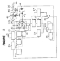
- FIG. 1 is a diagram showing a control circuit for the power assisted steering control apparatus of the present invention, wherein a reference numeral 20 designates a differentiation circuit, a numeral 21 designates a clutch driver for driving a clutch, a numeral 23 designates a torque neutral point detection circuit for detecting a neutral point of torque, a numeral 24 designates a self-sustaining circuit, a numeral 25 designates a fail-relay interrupting circuit, a numeral 26 designates a fail relay which comprises stationary contacts 41a, 41b, a movable contact 42 and an exciting coil 43, a numeral 27 designate a first level determining device, numerals 28 and 32 designate AND circuits, a numeral 29 designates a second level determining device, a numeral 30 designates a clutch current control circuit, a numeral 31 designates a clutch coil, and a numeral 36 designates a power source.
- the motor driving circuit 10 is constituted by a bridge circuit comprising four power MOS FETs 37-40.
- the fail relay 26 On activating the key switch 46, the fail relay 26 is activated and the movable contact 41 comes to contact with stationary contacts 41a, 41b, whereby a current is fed to the motor driving circuit 10 and the clutch driver 21 so that the motor 14 is connected to the steering shaft by means of the clutch.
- a steering torque produced in the steering wheel is detected by the torque sensor 1, and the output of the torque sensor is inputted to the CPU 3 and the torque neutral point detecting circuit 23 through the differentiation circuit 20.
- the CPU 3 processes the torque detection signal to detect the direction and the magnitude of the torque produced in the steering wheel, and outputs a signal to the motor driving circuit 10.
- the motor driving circuit 10 controls the magnitude and the direction of a current flowing in the motor 14 through the output terminals 44, 45, so that the motor 14 is driven.
- the driving force of the motor 14 is supplied to the steering shaft to thereby assist an operational force for the steering wheel.
- the motor current detection circuit 11 detects the current flowing in the motor through the resistor 12.
- the torque neutral point detecting circuit 23 detects the neutral point of torque T0, i.e. a neutral state of the steering wheel.
- the output of the torque neutral point detecting circuit 23 is inputted to the AND gate 28 along with the output of the second level determining device 29.
- the output of the AND gate 28 is supplied to the fail relay 26 through the self-sustaining circuit 24 and the fail-relay interrupting circuit 25.
- the output of the torque neutral point detecting circuit 23 is inputted to the AND gate 32 along with the output of the first level determinig device 27. And the output of the AND gate 32 is supplied to the clutch current control circuit 30.
- a control signal is supplied to the clutch current control circuit 30 to reduce the clutch current, whereby there occurs a slipage in the clutch. Accordingly, when the motor 14 falls in a state of locking or nearly locking while the motor current increases, the clutch current is reduced to thereby make the connection between the motor and the steering shaft loose to thereby bring the steering wheel into a state of manual operation.
- the AND gate 28 is turned on to open the fail relay 26, whereby the current supplied to the motor driving circuit 10 and the clutch driver 21 is interrupted. Accordingly, the steering wheel is brought to a state of complete manual operation.
- the steering wheel when the motor falls in a state of locking or nearly locking, the steering wheel is isolated from the clutch or the motor so that the steering wheel is brought into a state of manual operation or nearly manual operation. Accordinly, there is no possibility that the operator feels the operation of the steering wheel to be abnormally heavy, whereby an automobile can be safely driven.
Landscapes
- Engineering & Computer Science (AREA)
- Chemical & Material Sciences (AREA)
- Combustion & Propulsion (AREA)
- Transportation (AREA)
- Mechanical Engineering (AREA)
- Power Steering Mechanism (AREA)
- Steering Control In Accordance With Driving Conditions (AREA)
Applications Claiming Priority (2)
| Application Number | Priority Date | Filing Date | Title |
|---|---|---|---|
| JP63117388A JPH01285460A (ja) | 1988-05-13 | 1988-05-13 | 電動式パワーステアリング装置 |
| JP117388/88 | 1988-05-13 |
Publications (2)
| Publication Number | Publication Date |
|---|---|
| EP0341495A1 true EP0341495A1 (de) | 1989-11-15 |
| EP0341495B1 EP0341495B1 (de) | 1993-07-28 |
Family
ID=14710415
Family Applications (1)
| Application Number | Title | Priority Date | Filing Date |
|---|---|---|---|
| EP89107561A Expired - Lifetime EP0341495B1 (de) | 1988-05-13 | 1989-04-26 | Steuerung für eine Lenkung mit elektromotorischer Hilfskraft |
Country Status (5)
| Country | Link |
|---|---|
| US (1) | US4947949A (de) |
| EP (1) | EP0341495B1 (de) |
| JP (1) | JPH01285460A (de) |
| KR (1) | KR920006531B1 (de) |
| DE (1) | DE68907786T2 (de) |
Cited By (1)
| Publication number | Priority date | Publication date | Assignee | Title |
|---|---|---|---|---|
| EP0900711A3 (de) * | 1997-09-02 | 2000-06-14 | Koyo Seiko Co., Ltd. | Elektrische Servolenkung |
Families Citing this family (5)
| Publication number | Priority date | Publication date | Assignee | Title |
|---|---|---|---|---|
| EP0350817B1 (de) * | 1988-07-11 | 1995-04-19 | Koyo Seiko Co., Ltd. | Motorgetriebene Servolenkung |
| FR2667039B1 (fr) * | 1990-09-25 | 1993-06-18 | Renault | Direction assistee electrique de parking. |
| JP3212215B2 (ja) * | 1994-03-17 | 2001-09-25 | 三菱電機株式会社 | 電動パワーステアリング制御装置 |
| JP3724964B2 (ja) * | 1998-11-18 | 2005-12-07 | 株式会社デンソー | モータ駆動装置 |
| US8498781B2 (en) * | 2007-01-05 | 2013-07-30 | Steven J. Collier-Hallman | Methods and motor computer program products for motor control by the implementation of damping for over-speed conditions |
Citations (3)
| Publication number | Priority date | Publication date | Assignee | Title |
|---|---|---|---|---|
| EP0077696A1 (de) * | 1981-10-19 | 1983-04-27 | ACIERS ET OUTILLAGE PEUGEOT Société dite: | Servolenkungseinrichtung für Kraftfahrzeuge |
| JPS61205556A (ja) * | 1985-03-08 | 1986-09-11 | Hitachi Ltd | 電動式パワ−ステアリング装置の保護回路 |
| EP0249902A2 (de) * | 1986-06-12 | 1987-12-23 | Mitsubishi Denki Kabushiki Kaisha | Pannensicheres Verfahren und System für Motorgetriebenes Servolenkungsgerät |
Family Cites Families (8)
| Publication number | Priority date | Publication date | Assignee | Title |
|---|---|---|---|---|
| US4300650A (en) * | 1979-12-10 | 1981-11-17 | Weber Harold J | Multilevel power assisted steering |
| US4518055A (en) * | 1982-04-08 | 1985-05-21 | Nissan Motor Company, Limited | Pump-drive device of power-assisted steering system |
| US4621327A (en) * | 1984-06-13 | 1986-11-04 | Nartron Corporation | Electronic power steering method and apparatus |
| US4573545A (en) * | 1984-08-30 | 1986-03-04 | Eaton Corporation | Fail-safe device for an electrical power assisted steering system including an in-line clutch mechanism |
| JPH0662093B2 (ja) * | 1985-03-29 | 1994-08-17 | 豊田工機株式会社 | 電気式動力舵取装置 |
| JPH0798490B2 (ja) * | 1986-02-06 | 1995-10-25 | 本田技研工業株式会社 | 電動式パワーステアリング装置 |
| JPH0723104B2 (ja) * | 1986-04-22 | 1995-03-15 | 三菱電機株式会社 | モ−タ駆動式パワ−ステアリング制御装置 |
| JPS62283067A (ja) * | 1986-05-31 | 1987-12-08 | Aisin Seiki Co Ltd | 電動パワ−ステアリング装置 |
-
1988
- 1988-05-13 JP JP63117388A patent/JPH01285460A/ja active Pending
-
1989
- 1989-03-20 KR KR8903458A patent/KR920006531B1/ko not_active Expired
- 1989-04-26 US US07/343,310 patent/US4947949A/en not_active Expired - Fee Related
- 1989-04-26 EP EP89107561A patent/EP0341495B1/de not_active Expired - Lifetime
- 1989-04-26 DE DE89107561T patent/DE68907786T2/de not_active Expired - Fee Related
Patent Citations (3)
| Publication number | Priority date | Publication date | Assignee | Title |
|---|---|---|---|---|
| EP0077696A1 (de) * | 1981-10-19 | 1983-04-27 | ACIERS ET OUTILLAGE PEUGEOT Société dite: | Servolenkungseinrichtung für Kraftfahrzeuge |
| JPS61205556A (ja) * | 1985-03-08 | 1986-09-11 | Hitachi Ltd | 電動式パワ−ステアリング装置の保護回路 |
| EP0249902A2 (de) * | 1986-06-12 | 1987-12-23 | Mitsubishi Denki Kabushiki Kaisha | Pannensicheres Verfahren und System für Motorgetriebenes Servolenkungsgerät |
Non-Patent Citations (1)
| Title |
|---|
| PATENT ABSTRACTS OF JAPAN vol. 011, no. 039 (M - 559)<2486> 5 February 1987 (1987-02-05) * |
Cited By (1)
| Publication number | Priority date | Publication date | Assignee | Title |
|---|---|---|---|---|
| EP0900711A3 (de) * | 1997-09-02 | 2000-06-14 | Koyo Seiko Co., Ltd. | Elektrische Servolenkung |
Also Published As
| Publication number | Publication date |
|---|---|
| DE68907786T2 (de) | 1994-03-17 |
| DE68907786D1 (de) | 1993-09-02 |
| KR890017127A (ko) | 1989-12-15 |
| JPH01285460A (ja) | 1989-11-16 |
| US4947949A (en) | 1990-08-14 |
| EP0341495B1 (de) | 1993-07-28 |
| KR920006531B1 (en) | 1992-08-08 |
Similar Documents
| Publication | Publication Date | Title |
|---|---|---|
| KR910000398B1 (ko) | 모터구동식 동력조향 제어장치 | |
| KR880012422A (ko) | 전동식 파워스티어링장치 | |
| US5999870A (en) | Motor-driven power steering system for a vehicle and a method for controlling same | |
| EP0249902B1 (de) | Pannensicheres Verfahren und System für Motorgetriebenes Servolenkungsgerät | |
| JPH08244634A (ja) | 電動パワーステアリング制御装置 | |
| JPH062467B2 (ja) | 電動式パワーステアリング装置 | |
| JP2641245B2 (ja) | 電動式パワーステアリング装置 | |
| KR940004682B1 (ko) | 모터구동식 파워스테어링 제어장치 | |
| AU2003213428A1 (en) | Electric power steering device control apparatus | |
| KR930005849A (ko) | 전동파워 스티어링 제어장치 및 방법 | |
| KR900008031B1 (ko) | 모터구동식 파워스테어링 제어장치 | |
| US5507359A (en) | Electrically operated power steering control device | |
| EP0341495B1 (de) | Steuerung für eine Lenkung mit elektromotorischer Hilfskraft | |
| KR920005425B1 (ko) | 전동식 동력조향장치 | |
| JP4348848B2 (ja) | 電動パワーステアリング装置 | |
| KR900009002B1 (ko) | 모터구동식 파워스테어링 제어장치 | |
| KR900008033B1 (ko) | 모터 구동식 동력 조향 제어장치 | |
| JP3572801B2 (ja) | 電動パワーステアリング装置 | |
| KR900008034B1 (ko) | 모터 구동식 동력 조향 제어장치 | |
| JP3163920B2 (ja) | 電動パワーステアリング装置とそれに用いられるコントロールユニット | |
| JP2641243B2 (ja) | 電動式パワーステアリング装置 | |
| JPH05319296A (ja) | モータ駆動式パワーステアリング制御装置 | |
| JPH0311942B2 (de) | ||
| JPH0435071Y2 (de) | ||
| JP3261736B2 (ja) | 電動パワーステアリング装置 |
Legal Events
| Date | Code | Title | Description |
|---|---|---|---|
| PUAI | Public reference made under article 153(3) epc to a published international application that has entered the european phase |
Free format text: ORIGINAL CODE: 0009012 |
|
| AK | Designated contracting states |
Kind code of ref document: A1 Designated state(s): DE FR GB |
|
| 17P | Request for examination filed |
Effective date: 19891115 |
|
| 17Q | First examination report despatched |
Effective date: 19920706 |
|
| GRAA | (expected) grant |
Free format text: ORIGINAL CODE: 0009210 |
|
| AK | Designated contracting states |
Kind code of ref document: B1 Designated state(s): DE FR GB |
|
| REF | Corresponds to: |
Ref document number: 68907786 Country of ref document: DE Date of ref document: 19930902 |
|
| ET | Fr: translation filed | ||
| PLBE | No opposition filed within time limit |
Free format text: ORIGINAL CODE: 0009261 |
|
| STAA | Information on the status of an ep patent application or granted ep patent |
Free format text: STATUS: NO OPPOSITION FILED WITHIN TIME LIMIT |
|
| 26N | No opposition filed | ||
| PGFP | Annual fee paid to national office [announced via postgrant information from national office to epo] |
Ref country code: FR Payment date: 20010409 Year of fee payment: 13 |
|
| PGFP | Annual fee paid to national office [announced via postgrant information from national office to epo] |
Ref country code: DE Payment date: 20010418 Year of fee payment: 13 |
|
| PGFP | Annual fee paid to national office [announced via postgrant information from national office to epo] |
Ref country code: GB Payment date: 20010425 Year of fee payment: 13 |
|
| REG | Reference to a national code |
Ref country code: GB Ref legal event code: IF02 |
|
| PG25 | Lapsed in a contracting state [announced via postgrant information from national office to epo] |
Ref country code: GB Free format text: LAPSE BECAUSE OF NON-PAYMENT OF DUE FEES Effective date: 20020426 |
|
| PG25 | Lapsed in a contracting state [announced via postgrant information from national office to epo] |
Ref country code: DE Free format text: LAPSE BECAUSE OF NON-PAYMENT OF DUE FEES Effective date: 20021101 |
|
| GBPC | Gb: european patent ceased through non-payment of renewal fee |
Effective date: 20020426 |
|
| PG25 | Lapsed in a contracting state [announced via postgrant information from national office to epo] |
Ref country code: FR Free format text: LAPSE BECAUSE OF NON-PAYMENT OF DUE FEES Effective date: 20021231 |
|
| REG | Reference to a national code |
Ref country code: FR Ref legal event code: ST |