EP0341679A1 - Scie circulaire à table - Google Patents
Scie circulaire à table Download PDFInfo
- Publication number
- EP0341679A1 EP0341679A1 EP19890108361 EP89108361A EP0341679A1 EP 0341679 A1 EP0341679 A1 EP 0341679A1 EP 19890108361 EP19890108361 EP 19890108361 EP 89108361 A EP89108361 A EP 89108361A EP 0341679 A1 EP0341679 A1 EP 0341679A1
- Authority
- EP
- European Patent Office
- Prior art keywords
- saw
- lever
- table according
- saw table
- gear
- Prior art date
- Legal status (The legal status is an assumption and is not a legal conclusion. Google has not performed a legal analysis and makes no representation as to the accuracy of the status listed.)
- Granted
Links
- 238000006073 displacement reaction Methods 0.000 claims abstract description 11
- 238000005096 rolling process Methods 0.000 claims description 3
- 230000005540 biological transmission Effects 0.000 abstract description 9
- 230000002349 favourable effect Effects 0.000 abstract description 6
- 238000010276 construction Methods 0.000 abstract 1
- 230000000284 resting effect Effects 0.000 abstract 1
- 239000011295 pitch Substances 0.000 description 6
- 238000013016 damping Methods 0.000 description 1
- 238000011161 development Methods 0.000 description 1
- 230000018109 developmental process Effects 0.000 description 1
- 238000010586 diagram Methods 0.000 description 1
- 230000010354 integration Effects 0.000 description 1
- 238000000034 method Methods 0.000 description 1
- 238000003825 pressing Methods 0.000 description 1
- 230000001681 protective effect Effects 0.000 description 1
- 230000035939 shock Effects 0.000 description 1
- 230000003068 static effect Effects 0.000 description 1
Images



Classifications
-
- B—PERFORMING OPERATIONS; TRANSPORTING
- B23—MACHINE TOOLS; METAL-WORKING NOT OTHERWISE PROVIDED FOR
- B23D—PLANING; SLOTTING; SHEARING; BROACHING; SAWING; FILING; SCRAPING; LIKE OPERATIONS FOR WORKING METAL BY REMOVING MATERIAL, NOT OTHERWISE PROVIDED FOR
- B23D45/00—Sawing machines or sawing devices with circular saw blades or with friction saw discs
- B23D45/06—Sawing machines or sawing devices with circular saw blades or with friction saw discs with a circular saw blade arranged underneath a stationary work-table
- B23D45/061—Sawing machines or sawing devices with circular saw blades or with friction saw discs with a circular saw blade arranged underneath a stationary work-table the saw blade being mounted on a carriage
-
- B—PERFORMING OPERATIONS; TRANSPORTING
- B23—MACHINE TOOLS; METAL-WORKING NOT OTHERWISE PROVIDED FOR
- B23D—PLANING; SLOTTING; SHEARING; BROACHING; SAWING; FILING; SCRAPING; LIKE OPERATIONS FOR WORKING METAL BY REMOVING MATERIAL, NOT OTHERWISE PROVIDED FOR
- B23D47/00—Sawing machines or sawing devices working with circular saw blades, characterised only by constructional features of particular parts
- B23D47/02—Sawing machines or sawing devices working with circular saw blades, characterised only by constructional features of particular parts of frames; of guiding arrangements for work-table or saw-carrier
-
- B—PERFORMING OPERATIONS; TRANSPORTING
- B23—MACHINE TOOLS; METAL-WORKING NOT OTHERWISE PROVIDED FOR
- B23D—PLANING; SLOTTING; SHEARING; BROACHING; SAWING; FILING; SCRAPING; LIKE OPERATIONS FOR WORKING METAL BY REMOVING MATERIAL, NOT OTHERWISE PROVIDED FOR
- B23D47/00—Sawing machines or sawing devices working with circular saw blades, characterised only by constructional features of particular parts
- B23D47/08—Sawing machines or sawing devices working with circular saw blades, characterised only by constructional features of particular parts of devices for bringing the circular saw blade to the workpiece or removing same therefrom
-
- B—PERFORMING OPERATIONS; TRANSPORTING
- B23—MACHINE TOOLS; METAL-WORKING NOT OTHERWISE PROVIDED FOR
- B23D—PLANING; SLOTTING; SHEARING; BROACHING; SAWING; FILING; SCRAPING; LIKE OPERATIONS FOR WORKING METAL BY REMOVING MATERIAL, NOT OTHERWISE PROVIDED FOR
- B23D47/00—Sawing machines or sawing devices working with circular saw blades, characterised only by constructional features of particular parts
- B23D47/08—Sawing machines or sawing devices working with circular saw blades, characterised only by constructional features of particular parts of devices for bringing the circular saw blade to the workpiece or removing same therefrom
- B23D47/10—Sawing machines or sawing devices working with circular saw blades, characterised only by constructional features of particular parts of devices for bringing the circular saw blade to the workpiece or removing same therefrom actuated by fluid or gas pressure
Definitions
- the invention is based on a saw table according to the type of claim 1.
- Such saw tables enable the sawing of firmly clamped workpieces, similar to a cross-cut saw.
- a saw table with a firmly clamped saw unit is known in which the translation of the pivoting movement of the hand lever into the linear movement of the saw blade is effected by means of a cable pull attached to the end of the lever.
- the length of the displacement of the saw unit depends directly on the length of the lever. With the table height of 260 mm specified in the exemplary embodiment, this results in a displacement path of only approximately 150 mm if the pivoting angle of the hand lever is to remain within the ergonomically still acceptable range of less than 40 °.
- the saw table according to the invention with the characterizing features of claim 1 has the advantage that, with a compact design of the saw table, the displacement path of the saw blade is extended without leaving the ergonomically favorable pivoting range of the hand lever.
- the saw blade can be guided both forwards and backwards.
- the hand lever can also be replaced by an electric servomotor.
- Claims 13 to 19 relate to different designs of the transmission gear, a double spindle with different pitches allows a favorable translation. When using a ball screw, the friction is significantly reduced. A spindle drive, or a ball or roller guide simultaneously ensure that the carriage is guided straight for the saw blade or the motor. With the ball or roller guide, the swivel range of the lever can be easily adjusted.
- the use of hydraulic cylinders has the additional advantage that the return stroke is damped in the end positions of the displacement path. The speed-proportional damping is also advantageous and safer when sawing when the saw blade is jammed.
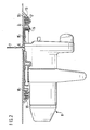
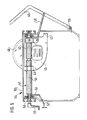
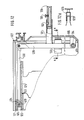
- the saw table 1 has a table top 2 with all-round guide and fastening strips 3 with preferably T-shaped grooves 4 (see also FIG. 5) for attaching stops 5.
- the table top 2 has an elongated slot 6 in its central region, which is located in the plane of a saw blade 7 which can be moved therein and which belongs to a saw unit 8 shown in FIG. For sawing, the saw blade 7 is moved in the feed direction indicated by an arrow.
- the table top 2 is connected to a housing 9 which has removable feet 10.
- swivel lever 13 consisting of two parallel pieces of pipe, which has at its free-standing end a handle 14 which is transverse to the pieces of pipe and connects them.
- the effective length L of the lever 13 from the handle 14 to its pivot point is preferably approximately 500-800 mm.
- the saw unit 8 shown in FIG. 2 is a commercially available hand-held circular saw with a base plate 15.
- the base plate 15 is mounted on a slide 17, for example with screws 16.
- the carriage 17 has rollers 18 which run in guides 19 of the table top 2.
- the carriage 17 can also be pivotally attached to the saw table 1 in order to bring the saw blade 7 into different angular positions with respect to the table top 2 for miter cuts.
- the guides 19 have a circular cross section in the regions that come into contact with the rollers 18, so that the rollers 18 engage behind the guides 19 with their adapted cup-shaped cross section. A horizontal and vertical fixing of the slide 17 with respect to the saw table 2 thus takes place immediately.
- a bevel gear 21 is shown as a gear 20 for translating the pivoting movement of the lever 13 into the linear movement of the saw unit 8.
- the pivot lever 13, which in this case preferably penetrates the rear wall 11 of the housing 9, is connected to a bevel gear 22.
- This bevel gear meshes with a bevel gear 23 arranged at right angles thereto.
- a roller 24 is seated on the shaft of the bevel gear 23, if appropriate at a suitable distance.
- a cable 26 is tensioned on which the Saw unit 8 or the carriage 17 is attached.
- the pivot lever 13 is plugged into a pipe section 27 so that it can be removed for transport. It can also be removed if the saw table is used as a conventional circular saw table with a fixed saw blade. In this case, the carriage 17 is locked and the workpiece is moved towards the saw blade in the usual manner during sawing.
- the cable can also be run over vertical rollers.
- a spur gear is used instead of the bevel gear.
- a ring gear can be used to reverse the direction of displacement of the motor.
- Planetary gears can also be used advantageously.
- a toothed belt or a chain (bicycle chain) can also be used.
- the ends of the rope or belt can also be wound a few turns around the deflection rollers, similar to a car window crank.
- the rope can also be guided over pulleys or guides e.g. like a Bowden cable.
- a return spring can be attached to the hand levers or the cable pulls according to the exemplary embodiments in FIGS. 1 and 2, which returns the saw blade to the starting position before sawing for safety reasons.
- a workpiece is placed on the table top, if necessary at the stop 5.
- the saw blade is initially in its rear position closest to lever 13. After the saw unit has been switched on, the lever 13 is pulled down in the direction of the arrow toward the operator standing in front of the saw table 1 until the handle 14 is approximately 200 mm from the table top 2 in its end position. The saw blade moves in the feed direction towards the operator along the slot 6.
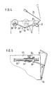
- the lever movement is translated into a linear movement by means of a sliding crank mechanism 30.
- the hand lever 31 is fastened to a toothed or friction wheel 32 which drives the toothed or friction wheel 33, which is connected to the lever 34 of the slider crank mechanism.
- the rod 35 is connected to the guide carriage 38 of the circular saw via joints 36 and 37.
- the position of the hand lever 31 and the gear 30 before the saw cut is shown in dashed lines.
- the thrust crank mechanism 30 is advantageously designed such that the dead centers do not fall within the driving range of the guide carriage.
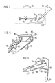
- a rotatably mounted spindle 40 has two areas 41 and 42 with possibly different pitches and / or different pitch directions, in each of which a nut 43 or 44 engages.
- the saw unit 45 is fastened to the nut 43 with the saw blade 46.
- the spindle 40 can simultaneously serve as a linear guide for the saw unit 45.
- the protective hood of the saw unit has a connecting piece 47 for a suction hose.
- the feed lever 49 is attached to the second nut 44 via a rod 48.
- a return spring 50 in the swivel joint of the feed lever ensures that the saw unit moves back automatically into the starting position shown in FIG.
- the spindle 40 alternatively has a hand crank 51 at its front end; An electric servomotor can also replace the hand crank.
- the spindle can be locked by means of a lever 52 with a locking member 53 for fixing the saw unit during transport or during table saw operation.
- the spindle gear (40, 43, 44) is inserted into a saw table 54 with a table top 55, which in turn has fastening strips 56 on the outer edge.
- the spindle 40 By moving the feed lever 49, the spindle 40 is rotated by the nut 44. The rotation of the spindle produces a linear movement of the saw unit 45 in the second nut 43.
- a gear ratio can be achieved by varying the thread pitch in the areas 41 and 42. For the threads, pitches between 30 ° and 50 ° are advantageous. If necessary, the threads can be multi-start.
- the nuts can be slide nuts or nuts with rolling elements, for example also ball nuts or part of a ball screw. In the simplest case offers a deep groove ball bearing without an inner ring and correspondingly rolled multi-start ball tracks on the spindle.
- the spindle drive can also serve as a guideway for the saw unit.
- the return spring 50 can be designed as a torsion spring with a round or rectangular cross section. Alternatively, a roller spring can also be attached, for example, directly to the saw unit 45.
- the spindle 60 is mounted in a rotationally rigid manner.
- a sleeve 61 with an internal and external thread is pushed over the thread of the spindle 60 by means of the pivot lever 62.
- the pivot lever 62 is articulated on a ring 63 which is rotatably but axially fixedly connected to the sleeve 61.
- the sleeve 61 rotates when the lever 62 is pivoted relative to the non-rotatable spindle 60 and a non-rotatable nut 64 on its external thread.
- the saw unit not shown, is attached to the outer nut 64.
- the desired route can be set by selecting the appropriate slope.
- the pivot lever 62 is articulated in a swivel joint 65 on the rear wall 66 of the saw table 67.
- the sleeve 61 moves on the spindle 60 from right to left or vice versa; at the same time the nut 64 moves away from the ring 63 of the sleeve 61 to the left or vice versa. This results in the desired extension of the travel path of the saw unit compared to the short lever travel.
- the rotatably mounted spindle 70 is provided with a bevel gear 71 which meshes with the bevel gear 72 of the hand lever 73.
- the saw unit not shown, is fastened to the saw blade 75 on the nut 74 which does not rotate.
- the hand lever can be replaced or supplemented by a servomotor in a simple manner.
- FIG. 8 shows a sixth exemplary embodiment of a spherical flat guide 79, which consists of an upper guide rail 80, a lower guide rail 81 and a ball cage 82.
- Balls 84 are held in the openings 83 of the ball cage 82.
- the ball cage 82 has fastening tabs 85.
- the balls 84 roll in the curved tracks 86 and 87 of the guide rails.
- the raceways are so braced against each other that a forced unrolling takes place in such a way that, when the lower guide rail 81 is held in place, the upper guide rail 80 moves in the longitudinal direction with respect to the ball cage 82 at twice the speed.
- the saw unit 90 with the saw blade 91 is firmly connected to the upper guide rail 80, which thus serves as a displaceable slide 80.
- the lower guide rail 81 is firmly connected to the housing of the underfloor saw 1.
- a rod 92, which is articulated on the feed lever 93, is fastened to the fastening tab 85 of the ball cage 82.
- the feed lever 93 is rotatable in the usual way in a joint 94 connected to the housing of the saw.
- the balls which are positively guided via frictional engagement, cause the second guideway 80 to move twice as much as the cage 82 itself when the cage 82 is driven, relative to the held guideway 81.
- the desired translation of the lever path into the linear movement of the saw unit 90 is thus achieved.
- the frictional forces of the balls can be designed, for example, at 100 N feed force. This means that sawing work can be carried out perfectly.
- slipping of the balls can be achieved, for example to put the pivoting lever position in an ergonomically favorable position for a certain sawing work.
- the flat guide also expediently serves as an aggregate linear guide.
- the integration of feed force introduction and linear guide is not only inexpensive, but it can also be attached particularly close to the saw blade. This has static advantages, because the ideal area for guiding and feeding force is in the saw blade level.
- FIGS. 10 and 11 show a further variant of a ball guide as the seventh exemplary embodiment.
- a carriage 100, on which the saw unit 101 is fastened, is displaceably mounted on the one hand in a slider 102, which is fastened to the table top 103 of a saw table 108.
- the other side of the carriage 100 has a guide tube 104.
- the guide rod 107 is firmly connected to the saw table 108.
- the cage 105 carries at its end a ring 109 on which the pivot lever 110 is articulated by means of a rod 111.
- the rod 111 passes through a slot 112 on the rear wall 113 of the saw table 108.
- the pivot lever 110 is also articulated in a swivel joint 114 on the rear wall 113.
- a bellows 115 is attached between the ring 109 and the guide tube 104.
- this ball guide 108 corresponds to that of the two previous exemplary embodiments.
- the guide tube 104 with the carriage 100 attached to it moves by the distance 2X.
- the balls can also be replaced by gear wheels 120 which run in racks 121 and 122 of two guide rails 123 and 124.
- the guide rail 124 is fixedly connected to the saw table 127, while a slide 125 is attached to the sliding guide rail 123 with a saw unit.
- a pivoting angle of the feed lever 128 of 30 °, there is a displacement path of the saw unit of 345 mm.
- the feed lever consists of a pipe section 128 with a handle (not shown) and a rod 129 to which a short pipe section 131 is welded, into which the pipe section 128 can be inserted and locked.
- the spring-loaded locking pin 132 which can be unlocked by pressing the button 133, serves this purpose.
- the rod 129 is mounted in a swivel joint 134 which is connected to the housing of the saw table 127 and is fastened to the rear wall 135 of the saw table 127 within the housing. In its position closest to the housing (as shown in FIG. 12), the rod 129 can be locked by means of a band spring 136 which surrounds it resiliently. In this position, the saw unit is fixed in place, so that the saw table 127 serves as a conventional circular saw table.
- a hydraulic transmission is used in the ninth embodiment.
- the hand lever 140 is connected to the piston 141 of the hydraulic cylinder 142.
- the two piston chambers of the cylinder 142 are optionally connected crosswise to the piston chambers of the hydraulic cylinder 143.
- the saw unit is connected to the piston 144 of this cylinder.
- a feed movement of the hand lever 140 at the same time causes a feed movement of the saw unit that is translated into faster because of the different piston dimensions.
- the direction of travel can be determined in a simple manner by appropriate selection of the line routing between the cylinders 142 and 143.
- the travel ratio can also be influenced according to the respective requirements by the choice of the piston diameter.
- FIG. 15 shows a portable underfloor saw table 149 which can also be used as a sliding table saw.
- the saw blade 150 is advantageously fixed stationary in any position in this use. However, as with the other exemplary embodiments, it can also be moved, preferably with a fixed table, by means of a lever (not shown).
- a part 151 of the table top can be moved longitudinally in the cutting direction of the saw blade.
- displaceable table half 151 is no longer than the fixed table top 156 and does not protrude beyond the housing 154. This makes it easier to tidy up and transport the saw table and serves to ensure safety against accidents.
- a workpiece is placed on the table top part 151 and moved together with the latter to the saw blade 150.
- the embodiment according to FIG. 15 enables both pulling cross-cut saws and fully-fledged format saws with a handy, sliding table that does not interfere with work. If necessary, both working methods can also be combined.
- the invention is not limited to the specific exemplary embodiments.
- the individual exemplary embodiments can be combined with others, in particular the gears can be exchanged.
- the function of the second and the following exemplary embodiments corresponds to that of the first example.
Landscapes
- Engineering & Computer Science (AREA)
- Mechanical Engineering (AREA)
- Sawing (AREA)
Applications Claiming Priority (2)
| Application Number | Priority Date | Filing Date | Title |
|---|---|---|---|
| DE3816125A DE3816125A1 (de) | 1988-05-11 | 1988-05-11 | Tischkreissaege |
| DE3816125 | 1988-05-11 |
Publications (2)
| Publication Number | Publication Date |
|---|---|
| EP0341679A1 true EP0341679A1 (fr) | 1989-11-15 |
| EP0341679B1 EP0341679B1 (fr) | 1993-08-04 |
Family
ID=6354180
Family Applications (1)
| Application Number | Title | Priority Date | Filing Date |
|---|---|---|---|
| EP89108361A Expired - Lifetime EP0341679B1 (fr) | 1988-05-11 | 1989-05-10 | Scie circulaire à table |
Country Status (2)
| Country | Link |
|---|---|
| EP (1) | EP0341679B1 (fr) |
| DE (2) | DE3816125A1 (fr) |
Cited By (7)
| Publication number | Priority date | Publication date | Assignee | Title |
|---|---|---|---|---|
| EP0689907A1 (fr) * | 1994-06-28 | 1996-01-03 | Otto Martin Maschinenbau GmbH & Co. | Machine de travail du bois |
| DE19536187C1 (de) * | 1995-09-28 | 1996-12-12 | Metabowerke Kg | Transportable Tischkreissäge |
| US6463837B2 (en) | 1997-03-20 | 2002-10-15 | Emex As | Guiding device for a saw blade |
| EP1839791A3 (fr) * | 2006-03-31 | 2007-11-21 | Metabowerke GmbH & Co. | Scie circulaire à table |
| CN103358360A (zh) * | 2013-08-06 | 2013-10-23 | 颜夏根 | 一种木工锯床 |
| IT201800005489A1 (it) * | 2018-05-18 | 2019-11-18 | Macchina per la levigatura di pezzi. | |
| CN116394353A (zh) * | 2023-05-19 | 2023-07-07 | 成都建工第三建筑工程有限公司 | 一种应用于建筑板材的切割加工装置 |
Families Citing this family (1)
| Publication number | Priority date | Publication date | Assignee | Title |
|---|---|---|---|---|
| EP1060061B1 (fr) * | 1998-03-06 | 2002-09-18 | Ernex AS | Scie de menuisier |
Citations (1)
| Publication number | Priority date | Publication date | Assignee | Title |
|---|---|---|---|---|
| EP0066275A1 (fr) * | 1981-06-03 | 1982-12-08 | Arnim Schulte | Table à scie |
-
1988
- 1988-05-11 DE DE3816125A patent/DE3816125A1/de not_active Withdrawn
-
1989
- 1989-05-10 DE DE8989108361T patent/DE58905100D1/de not_active Expired - Lifetime
- 1989-05-10 EP EP89108361A patent/EP0341679B1/fr not_active Expired - Lifetime
Patent Citations (1)
| Publication number | Priority date | Publication date | Assignee | Title |
|---|---|---|---|---|
| EP0066275A1 (fr) * | 1981-06-03 | 1982-12-08 | Arnim Schulte | Table à scie |
Cited By (9)
| Publication number | Priority date | Publication date | Assignee | Title |
|---|---|---|---|---|
| EP0689907A1 (fr) * | 1994-06-28 | 1996-01-03 | Otto Martin Maschinenbau GmbH & Co. | Machine de travail du bois |
| DE19536187C1 (de) * | 1995-09-28 | 1996-12-12 | Metabowerke Kg | Transportable Tischkreissäge |
| US6463837B2 (en) | 1997-03-20 | 2002-10-15 | Emex As | Guiding device for a saw blade |
| EP1839791A3 (fr) * | 2006-03-31 | 2007-11-21 | Metabowerke GmbH & Co. | Scie circulaire à table |
| CN103358360A (zh) * | 2013-08-06 | 2013-10-23 | 颜夏根 | 一种木工锯床 |
| CN103358360B (zh) * | 2013-08-06 | 2015-05-06 | 颜夏根 | 一种木工锯床 |
| IT201800005489A1 (it) * | 2018-05-18 | 2019-11-18 | Macchina per la levigatura di pezzi. | |
| CN116394353A (zh) * | 2023-05-19 | 2023-07-07 | 成都建工第三建筑工程有限公司 | 一种应用于建筑板材的切割加工装置 |
| CN116394353B (zh) * | 2023-05-19 | 2023-08-22 | 成都建工第三建筑工程有限公司 | 一种应用于建筑板材的切割加工装置 |
Also Published As
| Publication number | Publication date |
|---|---|
| EP0341679B1 (fr) | 1993-08-04 |
| DE3816125A1 (de) | 1989-12-07 |
| DE58905100D1 (de) | 1993-09-09 |
Similar Documents
| Publication | Publication Date | Title |
|---|---|---|
| EP0175643B1 (fr) | Perceuse sur montant avec colonne de guidage | |
| DE69831558T2 (de) | Tragbares Schneidgerät | |
| DE2945770A1 (de) | Bearbeitungszentrum | |
| EP0341679B1 (fr) | Scie circulaire à table | |
| EP2106317A1 (fr) | Scie encastrée motorisée, fixe | |
| DE2530365A1 (de) | Einrichtung zur durchmesserverstellung einer walze | |
| EP0615807B1 (fr) | Scie de précision à table ayant une rigidité de torsion améliorée des éléments de structure | |
| DE2555150C2 (de) | Vorrichtung zum Erzeugen des Längsvorschubes von Greiferschienen für eine Stufenpresse | |
| DE4411257C2 (de) | Sägemaschine für Gehrungs- und Schifterschnitte | |
| DE3217705C2 (de) | Trennschleifmaschine | |
| DE2613092B2 (de) | Motorsäge | |
| DE4033785C2 (fr) | ||
| DE3347920A1 (de) | Saegeeinrichtung | |
| EP1285722B1 (fr) | Perceuse radiale | |
| DE4310268C1 (de) | Schutzhaubenträger, insbesondere für eine Tischkreissäge | |
| DE2505985B2 (de) | Saegenschaerfmaschine zum schaerfen von zaehnen unterschiedlicher zahnspitzenhoehe | |
| DE3817193C2 (fr) | ||
| DE8624943U1 (de) | Teleskopartig ausfahrbare Handhabungs- oder Transporteinrichtung | |
| DE575799C (de) | Tragbare Saegemaschine | |
| DE2633098B2 (de) | Waagerecht-AuBen-Räummaschine | |
| DE1704789A1 (de) | Schaumstoff-Schneidemaschine | |
| DE504195C (de) | Schaber mit Kraftbetrieb | |
| EP0260477B1 (fr) | Machine à brochage verticale | |
| AT256589B (de) | Rohrbrennschneidmaschine | |
| EP0082446A2 (fr) | Tour pour bois |
Legal Events
| Date | Code | Title | Description |
|---|---|---|---|
| PUAI | Public reference made under article 153(3) epc to a published international application that has entered the european phase |
Free format text: ORIGINAL CODE: 0009012 |
|
| AK | Designated contracting states |
Kind code of ref document: A1 Designated state(s): DE GB IT |
|
| 17P | Request for examination filed |
Effective date: 19900507 |
|
| 17Q | First examination report despatched |
Effective date: 19910430 |
|
| RAP3 | Party data changed (applicant data changed or rights of an application transferred) |
Owner name: ROBERT BOSCH GMBH |
|
| GRAA | (expected) grant |
Free format text: ORIGINAL CODE: 0009210 |
|
| AK | Designated contracting states |
Kind code of ref document: B1 Designated state(s): DE GB IT |
|
| GBT | Gb: translation of ep patent filed (gb section 77(6)(a)/1977) |
Effective date: 19930806 |
|
| REF | Corresponds to: |
Ref document number: 58905100 Country of ref document: DE Date of ref document: 19930909 |
|
| ITF | It: translation for a ep patent filed | ||
| PLBE | No opposition filed within time limit |
Free format text: ORIGINAL CODE: 0009261 |
|
| STAA | Information on the status of an ep patent application or granted ep patent |
Free format text: STATUS: NO OPPOSITION FILED WITHIN TIME LIMIT |
|
| 26N | No opposition filed | ||
| PGFP | Annual fee paid to national office [announced via postgrant information from national office to epo] |
Ref country code: GB Payment date: 19990426 Year of fee payment: 11 |
|
| PG25 | Lapsed in a contracting state [announced via postgrant information from national office to epo] |
Ref country code: GB Free format text: LAPSE BECAUSE OF NON-PAYMENT OF DUE FEES Effective date: 20000510 |
|
| GBPC | Gb: european patent ceased through non-payment of renewal fee |
Effective date: 20000510 |
|
| PG25 | Lapsed in a contracting state [announced via postgrant information from national office to epo] |
Ref country code: IT Free format text: LAPSE BECAUSE OF NON-PAYMENT OF DUE FEES;WARNING: LAPSES OF ITALIAN PATENTS WITH EFFECTIVE DATE BEFORE 2007 MAY HAVE OCCURRED AT ANY TIME BEFORE 2007. THE CORRECT EFFECTIVE DATE MAY BE DIFFERENT FROM THE ONE RECORDED. Effective date: 20050510 |
|
| PGFP | Annual fee paid to national office [announced via postgrant information from national office to epo] |
Ref country code: DE Payment date: 20080728 Year of fee payment: 20 |