EP0341890B1 - Automatische Fahrzeugsteuerung - Google Patents
Automatische Fahrzeugsteuerung Download PDFInfo
- Publication number
- EP0341890B1 EP0341890B1 EP89304450A EP89304450A EP0341890B1 EP 0341890 B1 EP0341890 B1 EP 0341890B1 EP 89304450 A EP89304450 A EP 89304450A EP 89304450 A EP89304450 A EP 89304450A EP 0341890 B1 EP0341890 B1 EP 0341890B1
- Authority
- EP
- European Patent Office
- Prior art keywords
- vehicle
- initialisation
- reflectors
- navigation system
- area
- Prior art date
- Legal status (The legal status is an assumption and is not a legal conclusion. Google has not performed a legal analysis and makes no representation as to the accuracy of the status listed.)
- Expired - Lifetime
Links
Images

Classifications
-
- G—PHYSICS
- G05—CONTROLLING; REGULATING
- G05D—SYSTEMS FOR CONTROLLING OR REGULATING NON-ELECTRIC VARIABLES
- G05D1/00—Control of position, course, altitude or attitude of land, water, air or space vehicles, e.g. using automatic pilots
- G05D1/02—Control of position or course in two dimensions
- G05D1/021—Control of position or course in two dimensions specially adapted to land vehicles
- G05D1/0231—Control of position or course in two dimensions specially adapted to land vehicles using optical position detecting means
- G05D1/0234—Control of position or course in two dimensions specially adapted to land vehicles using optical position detecting means using optical markers or beacons
- G05D1/0236—Control of position or course in two dimensions specially adapted to land vehicles using optical position detecting means using optical markers or beacons in combination with a laser
-
- G—PHYSICS
- G05—CONTROLLING; REGULATING
- G05D—SYSTEMS FOR CONTROLLING OR REGULATING NON-ELECTRIC VARIABLES
- G05D1/00—Control of position, course, altitude or attitude of land, water, air or space vehicles, e.g. using automatic pilots
- G05D1/20—Control system inputs
- G05D1/24—Arrangements for determining position or orientation
- G05D1/244—Arrangements for determining position or orientation using passive navigation aids external to the vehicle, e.g. markers, reflectors or magnetic means
-
- G—PHYSICS
- G01—MEASURING; TESTING
- G01S—RADIO DIRECTION-FINDING; RADIO NAVIGATION; DETERMINING DISTANCE OR VELOCITY BY USE OF RADIO WAVES; LOCATING OR PRESENCE-DETECTING BY USE OF THE REFLECTION OR RERADIATION OF RADIO WAVES; ANALOGOUS ARRANGEMENTS USING OTHER WAVES
- G01S17/00—Systems using the reflection or reradiation of electromagnetic waves other than radio waves, e.g. lidar systems
- G01S17/02—Systems using the reflection of electromagnetic waves other than radio waves
- G01S17/06—Systems determining position data of a target
-
- G—PHYSICS
- G01—MEASURING; TESTING
- G01S—RADIO DIRECTION-FINDING; RADIO NAVIGATION; DETERMINING DISTANCE OR VELOCITY BY USE OF RADIO WAVES; LOCATING OR PRESENCE-DETECTING BY USE OF THE REFLECTION OR RERADIATION OF RADIO WAVES; ANALOGOUS ARRANGEMENTS USING OTHER WAVES
- G01S17/00—Systems using the reflection or reradiation of electromagnetic waves other than radio waves, e.g. lidar systems
- G01S17/87—Combinations of systems using electromagnetic waves other than radio waves
-
- G—PHYSICS
- G05—CONTROLLING; REGULATING
- G05D—SYSTEMS FOR CONTROLLING OR REGULATING NON-ELECTRIC VARIABLES
- G05D1/00—Control of position, course, altitude or attitude of land, water, air or space vehicles, e.g. using automatic pilots
- G05D1/60—Intended control result
- G05D1/646—Following a predefined trajectory, e.g. a line marked on the floor or a flight path
Definitions
- This invention relates to the control of automated vehicles which move around a site, such as a factory or a warehouse, in accordance with control signals generated by a computer.
- the invention is particularly relevant to vehicles which are controlled over radio or other remote control links and do not rely on guidance wires or tracks.
- Each vehicle has a scanning laser beam which rotates in azimuth so that it scans across a number of reflector boards which are spaced apart around the site.
- Each reflector board is provided with uniquely coded strips of a retro-reflective material which is such that the laser beam incident thereon is reflected back along the same path.
- Each vehicle is thereby able, using triangulation techniques, to determine its own position relative to any location within the site.
- Each vehicle monitors its own position as it moves along a path to its required destination, and continuously transmits its position back to the base station, so that the base station can control the truck movements so as to avoid collisions.
- the retro-reflective stripes and the non-reflective stripes therebetween form a unique bar code on each reflector board.
- the stripes are scanned sequentially by the laser beam, the first few stripes in the sequence provide a code which confirms that a reflector board has been found (as distinct from any other reflective body which might be encountered).
- the next stripes in the sequence identify the particular target board which is being interrogated, and the final stripe indicates the position of the end of the reflector board with a high degree of accuracy, for determination of the position of the vehicle.
- the reflector boards must not be made too large, or they will encroach upon the area available for vehicle and personnel movements.
- the strips must not be too narrow, or the reliability of code reading will be unacceptable. It follows, therefore, that, for an acceptable board size and an acceptable stripe width, only a limited number of stripes, and hence only a limited number of uniquely-coded boards, can be provided.
- a method of operating a vehicle guidance and control system of the kind including a vehicle having motive power and steering, a navigation system and means for transmitting a directional laser beam which is scanned in a predetermined sense; a plurality of reflectors spaced apart from each other, each incorporating an optical code which identifies that reflector, and each of which is located so as to be capable of intercepting the laser beam; and means to utilise light reflected back to the vehicle by at least two reflectors for controlling the movement and heading of the vehicle; the method comprising the steps of notionally dividing an area in which the vehicle is to operate into a plurality of equal sub-areas of predetermined dimensions, each provided with a plurality of the reflectors; positioning the vehicle at an initial location from which its laser beam can scan initialisation reflectors located at positions selected for initialisation of its navigation system; feeding to the navigation system data defining the positions of the initialisation reflectors; and causing the navigation system to determine the position of the vehicle with respect to the initialisation reflectors;
- three initialisation reflectors will be scanned, unless the vehicle has means, such as compass, for determining its heading, when two reflectors will be sufficient.
- the method of the present invention allows duplication of reflector codes in different sub-areas, because at any instant the vehicle can determine in which sub-area it is located and so can differentiate between a reflector in one sub-area and an identically-coded reflector in another sub-area.
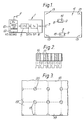
- a controller 1 for controlling the movement of vehicles, such as the vehicles 2 and 3, around an area 4 comprises a computer 5 which generates vehicle control signals which are fed to a radio transmitter 6.
- the signals are used to modulate a carrier wave which is transmitted via an antenna 7 and is received by antennas 8 and 9 on the vehicles 2 and 3.
- Data are fed into the computer 5 from data input means 10 which includes a radio receiver which receives position data from the vehicles 2 and 3 via an antenna 11.
- the data may alternatively be transmitted by other means, such as via an ultra sonic or laser link.
- the data input means may also comprise sensors for the automatic sensing of conditions within the area, and a keyboard 12 is provided for manual data entry.
- the navigation system of each vehicle is preferably as described in our above-mentioned British Patent No: 2,143,395.
- coded retro-reflective targets 13 are positioned around the area 4.
- Rotary laser scanners 14, 15 are fitted on the vehicles 2 and 3, respectively, and the navigation system of each vehicle continuously determines, from reflections from the coded targets, and by triangulation, the exact position of the respective vehicle relative to those targets.
- Figure 2 shows an example of a coded reflective target 13.
- the target has alternate reflective stripes 16 and non-reflective stripes 17.
- the widths of the stripes determine the code elements, so that a wide reflective stripe followed by a narrow non-reflective stripe represents a digital 1 element, and a narrow reflective stripe followed by a wide non-reflective stripe represents a digital 0 element.
- a number of the code elements are used to confirm that the laser beam reflections are received from a target and not from some other reflective surface.
- the number of pairs of stripes available for encoding the target identity, without making the target excessively large, may be limited to, say, five, so that only thirty-two different reflector codes can be achieved.
- Figure 3 represents a plan of part of a very large area 18 over which vehicles are to move.
- Such area may be, for example, 700m x 400m.
- the reflective targets must not be spaced apart by more than, say, 40m.
- the area is therefore divided into sub-areas 19, which are preferably square and are preferably of 32.767 metres side. The latter dimension is chosen as convenient when a 16-bit word is used for characterising the position, the most significant bit being used to indicate polarity. The largest number which can be represented by the remaining fifteen bits is then 32,767.
- Four reflective targets 13 are located in each square, the targets being affixed to walls, where available, or otherwise to posts 20 or other supports.
- a vehicle such as the vehicle 2
- its scanner scans the datum targets so that its navigation system can accurately determine the initial position of the vehicle relative to those targets, and its initial heading.
- the navigation system keeps a record of the present distance of the vehicle from the initialisation datum position and the present heading of the vehicle. In that way the navigation system always has a record of which sub-area is occupied by the vehicle at any instant and can then determine positional data accurately from the targets in that sub-area.
- the datum targets may be located at any other desired position within or alongside the area 18. Indeed, three of the targets 13 within any of the sub-areas may be treated as datum targets. One or more further sets of datum targets may be located around the area to avoid the need for the vehicle to travel a large distance for the initialisation process.
Landscapes
- Physics & Mathematics (AREA)
- Engineering & Computer Science (AREA)
- Electromagnetism (AREA)
- General Physics & Mathematics (AREA)
- Radar, Positioning & Navigation (AREA)
- Remote Sensing (AREA)
- Computer Networks & Wireless Communication (AREA)
- Aviation & Aerospace Engineering (AREA)
- Automation & Control Theory (AREA)
- Optics & Photonics (AREA)
- Control Of Position, Course, Altitude, Or Attitude Of Moving Bodies (AREA)
- Navigation (AREA)
Claims (5)
- Verfahren zum Betreiben eines Fahrzeugführungs- und Steuersystems der Art, die enthält ein Fahrzeug (2, 3), das über Triebkraft und Lenkung verfügt, ein Navigationssystem und eine Einrichtung (14, 15) zum Aussenden eines gerichteten Laserstrahls, der in einer vorbestimmten Richtung gescanned wird; mehrere Reflektoren (13), die voneinander beabstandet sind und jeweils einen optischen Code (16, 17) enthalten, der den Reflektor identifiziert, und von denen jeder so angeordnet ist, daß er imstande ist, den Laserstrahl zu unterbrechen; und eine Einrichtung zur Ausnutzung des Lichts, das zum Fahrzeug durch zumindest zwei Reflektoren zurückreflektiert worden ist, zur Steuerung der Bewegung und des Steuerkurses des Fahrzeugs; gekennzeichnet durch die Schritte der fiktiven Unterteilung eines Bereichs (18), in dem das Fahrzeug wirken soll, in mehrere gleicher Teilbereiche (19) vorbestimmter Abmessungen, von denen jeder mit mehreren Reflektoren versehen ist; Positionieren des Fahrzeugs an einer Anfangsposition (24), von der aus sein Laserstrahl Initialisierungsreflektoren (21-23) abtasten kann, die an Positionen liegen, die zur Initialisierung seines Navigationssystems ausgewählt sind; Zuführen von Daten, die die Positionen der Initialisierungsreflektoren definieren, zum Navigationssystem; und Veranlassen des Navigationssystems, die Position des Fahrzeugs bezüglich der Initialisierungsreflektoren zu ermitteln; wobei während darauffolgender Bewegung des Fahrzeugs im Bereich umher das Navigationssystem durch Messen von Distanzen und Richtungen, die vom Fahrzeug aus dieser Anfangsposition gefahren werden, funktionswirksam ist, zu ermitteln, in welchem Teilbereich das Fahrzeug zu jedwedem Moment lokalisiert ist.
- Verfahren nach Anspruch 1, dadurch gekennzeichnet, daß drei Initialisierungsreflektoren (21-23) verwendet werden, um die Anfangspositions- und Steuerkursdaten zur Initialisierung des Navigationssystems zu liefern.
- Verfahren nach Anspruch 1, dadurch gekennzeichnet, daß zwei Initialisierungsreflektoren (21-23) verwendet werden, um Anfangspositionsdaten zur Initialisierung des Navigationssystems zu liefern; und daß eine Einrichtung am Fahrzeug (2, 3) vorgesehen ist, um den Steuerkurs des Fahrzeugs während der Initialisierung des Navigationssystems zu bestimmen.
- Verfahren nach einem vorhergehenden Anspruch, dadurch gekennzeichnet, daß die die Positionen der Initialisierungsreflektoren (21-23) definierenden Daten dem Navigationssystem über eine Datenübertragung (7, 8, 9, 11) zugeführt werden, die durch den freien Raum überträgt.
- Verfahren nach Anspruch 4, dadurch gekennzeichnet, daß die Übertragung (7, 8, 9, 11) eine Funkverbindung ist.
Applications Claiming Priority (2)
| Application Number | Priority Date | Filing Date | Title |
|---|---|---|---|
| GB8811442A GB2218590B (en) | 1988-05-13 | 1988-05-13 | Automated vehicle control |
| GB8811442 | 1988-05-13 |
Publications (3)
| Publication Number | Publication Date |
|---|---|
| EP0341890A2 EP0341890A2 (de) | 1989-11-15 |
| EP0341890A3 EP0341890A3 (en) | 1990-12-19 |
| EP0341890B1 true EP0341890B1 (de) | 1993-08-11 |
Family
ID=10636904
Family Applications (1)
| Application Number | Title | Priority Date | Filing Date |
|---|---|---|---|
| EP89304450A Expired - Lifetime EP0341890B1 (de) | 1988-05-13 | 1989-05-03 | Automatische Fahrzeugsteuerung |
Country Status (8)
| Country | Link |
|---|---|
| US (1) | US5005128A (de) |
| EP (1) | EP0341890B1 (de) |
| JP (1) | JP2741403B2 (de) |
| KR (1) | KR970002256B1 (de) |
| DE (1) | DE68908259T2 (de) |
| ES (1) | ES2045423T3 (de) |
| GB (1) | GB2218590B (de) |
| IE (1) | IE60924B1 (de) |
Families Citing this family (40)
| Publication number | Priority date | Publication date | Assignee | Title |
|---|---|---|---|---|
| US5237164A (en) * | 1989-05-12 | 1993-08-17 | Sony Corporation | Card having retroreflective bar codes and a magnetic stripe |
| JP2868847B2 (ja) * | 1990-06-27 | 1999-03-10 | 本田技研工業株式会社 | 自走車の操向制御装置 |
| US5281901A (en) * | 1990-12-03 | 1994-01-25 | Eaton-Kenway, Inc. | Downward compatible AGV system and methods |
| GB2259210B (en) * | 1991-08-30 | 1995-10-04 | Marconi Gec Ltd | Aircraft ground movement monitor |
| IL100633A (en) * | 1992-01-12 | 1999-04-11 | Israel State | Large area movement robot |
| US5279672A (en) * | 1992-06-29 | 1994-01-18 | Windsor Industries, Inc. | Automatic controlled cleaning machine |
| IT1272491B (it) * | 1993-07-29 | 1997-06-23 | Renato Zaccaria | Metodo per il rilevamento della posizione di un veicolo mobile in un' aerea delimitata e dispositivo che realizza tale metodo |
| US5367458A (en) * | 1993-08-10 | 1994-11-22 | Caterpillar Industrial Inc. | Apparatus and method for identifying scanned reflective anonymous targets |
| IL109360A0 (en) * | 1994-04-20 | 1994-10-07 | Siman Sensors & Intelligent Ma | Navigation system for fast automated vehicles and mobile robots |
| GB2325807B (en) * | 1997-05-30 | 2002-03-20 | British Broadcasting Corp | Position determination |
| WO1998054593A1 (en) | 1997-05-30 | 1998-12-03 | British Broadcasting Corporation | Position determination |
| AUPP299498A0 (en) | 1998-04-15 | 1998-05-07 | Commonwealth Scientific And Industrial Research Organisation | Method of tracking and sensing position of objects |
| EP1103824A3 (de) * | 1999-11-23 | 2002-08-28 | Xerox Corporation | Virtueles Steuerungssystem mit Verwendung von nicht-bilderzeugenden Scannern |
| SE519481C2 (sv) * | 2000-06-22 | 2003-03-04 | Tts Ships Equipment Ab | Anordning vid Ro-Ro fartyg |
| US6556598B1 (en) * | 2000-07-21 | 2003-04-29 | Self-Guided Systems, Llc | Laser guidance assembly for a vehicle |
| RU2180311C1 (ru) * | 2001-07-05 | 2002-03-10 | Мешалкин Георгий Алексеевич | Защитная пробка |
| US7533435B2 (en) | 2003-05-14 | 2009-05-19 | Karcher North America, Inc. | Floor treatment apparatus |
| EP1517117A1 (de) * | 2003-09-22 | 2005-03-23 | Leica Geosystems AG | Verfahren und System zur Bestimmung einer Aktualposition eines Positionierungsgerätes |
| US7706917B1 (en) | 2004-07-07 | 2010-04-27 | Irobot Corporation | Celestial navigation system for an autonomous robot |
| US8966693B2 (en) | 2009-08-05 | 2015-03-03 | Karcher N. America, Inc. | Method and apparatus for extended use of cleaning fluid in a floor cleaning machine |
| US8224516B2 (en) | 2009-12-17 | 2012-07-17 | Deere & Company | System and method for area coverage using sector decomposition |
| US20110153338A1 (en) * | 2009-12-17 | 2011-06-23 | Noel Wayne Anderson | System and method for deploying portable landmarks |
| US8635015B2 (en) * | 2009-12-17 | 2014-01-21 | Deere & Company | Enhanced visual landmark for localization |
| ES2401509B1 (es) * | 2011-10-05 | 2014-03-05 | Universidad De Almería | Sistema de guiado para movimiento autónomo de vehículos en entornos estructurados. |
| DE202014104780U1 (de) | 2013-12-04 | 2014-10-29 | Götting KG | Fahrerloses flurgebundenes Fahrzeug |
| CN104515441B (zh) * | 2014-12-26 | 2015-12-02 | 中国人民解放军总装备部军械技术研究所 | 一种涡轮保险引信性能测试起爆防护装置 |
| JP6656673B2 (ja) * | 2015-06-10 | 2020-03-04 | 株式会社Doog | 自律移動システム |
| CN105157697B (zh) * | 2015-07-31 | 2017-05-17 | 天津大学 | 基于光电扫描的室内移动机器人位姿测量系统及测量方法 |
| US10683171B2 (en) | 2016-09-30 | 2020-06-16 | Staples, Inc. | Hybrid modular storage fetching system |
| US10589931B2 (en) | 2016-09-30 | 2020-03-17 | Staples, Inc. | Hybrid modular storage fetching system |
| EP3519937A4 (de) | 2016-09-30 | 2020-04-29 | Staples, Inc. | Hybrides modulares speicherabrufsystem |
| WO2018202301A1 (de) | 2017-05-04 | 2018-11-08 | Alfred Kärcher SE & Co. KG | Bodenreinigungsgerät und verfahren zum reinigen einer bodenfläche |
| US11590997B1 (en) | 2018-08-07 | 2023-02-28 | Staples, Inc. | Autonomous shopping cart |
| US11084410B1 (en) | 2018-08-07 | 2021-08-10 | Staples, Inc. | Automated guided vehicle for transporting shelving units |
| US11630447B1 (en) | 2018-08-10 | 2023-04-18 | Staples, Inc. | Automated guided vehicle for transporting objects |
| US11180069B2 (en) | 2018-12-31 | 2021-11-23 | Staples, Inc. | Automated loading of delivery vehicles using automated guided vehicles |
| US11119487B2 (en) | 2018-12-31 | 2021-09-14 | Staples, Inc. | Automated preparation of deliveries in delivery vehicles using automated guided vehicles |
| USD907868S1 (en) | 2019-01-24 | 2021-01-12 | Karcher North America, Inc. | Floor cleaner |
| US11124401B1 (en) | 2019-03-31 | 2021-09-21 | Staples, Inc. | Automated loading of delivery vehicles |
| CN110262474B (zh) * | 2019-05-06 | 2022-04-05 | 深圳市恒天伟焱科技股份有限公司 | 一种激光导引小车行进线路的自动控制系统及方法 |
Family Cites Families (7)
| Publication number | Priority date | Publication date | Assignee | Title |
|---|---|---|---|---|
| US4225226A (en) * | 1978-12-29 | 1980-09-30 | Spectra-Physics, Inc. | Laser guidance system for crop spraying aircraft |
| GB2143395B (en) * | 1983-05-14 | 1986-08-06 | Gen Electric Co Plc | Vehicle guidance and control system |
| US4700301A (en) * | 1983-11-02 | 1987-10-13 | Dyke Howard L | Method of automatically steering agricultural type vehicles |
| US4716530A (en) * | 1984-05-21 | 1987-12-29 | Kabushiki Kaisha Meidensha | System for automatically controlling movement of unmanned vehicle and method therefor |
| US4670648A (en) * | 1985-03-06 | 1987-06-02 | University Of Cincinnati | Omnidirectional vision system for controllng mobile machines |
| DE3686379T2 (de) * | 1985-08-30 | 1993-03-11 | Texas Instruments Inc | Regler fuer ein ferngesteuertes fahrzeug unter verwendung der verzoegerten absoluten positionsdaten fuer lenkung und navigation. |
| US4796198A (en) * | 1986-10-17 | 1989-01-03 | The United States Of America As Represented By The United States Department Of Energy | Method for laser-based two-dimensional navigation system in a structured environment |
-
1988
- 1988-05-13 GB GB8811442A patent/GB2218590B/en not_active Expired - Lifetime
-
1989
- 1989-05-02 IE IE143089A patent/IE60924B1/en unknown
- 1989-05-02 US US07/346,129 patent/US5005128A/en not_active Expired - Lifetime
- 1989-05-03 DE DE89304450T patent/DE68908259T2/de not_active Expired - Fee Related
- 1989-05-03 ES ES89304450T patent/ES2045423T3/es not_active Expired - Lifetime
- 1989-05-03 EP EP89304450A patent/EP0341890B1/de not_active Expired - Lifetime
- 1989-05-11 KR KR1019890006349A patent/KR970002256B1/ko not_active Expired - Fee Related
- 1989-05-11 JP JP1118489A patent/JP2741403B2/ja not_active Expired - Fee Related
Also Published As
| Publication number | Publication date |
|---|---|
| KR900018778A (ko) | 1990-12-22 |
| DE68908259T2 (de) | 1993-11-25 |
| JP2741403B2 (ja) | 1998-04-15 |
| EP0341890A3 (en) | 1990-12-19 |
| ES2045423T3 (es) | 1994-01-16 |
| GB8811442D0 (en) | 1988-06-15 |
| US5005128A (en) | 1991-04-02 |
| DE68908259D1 (de) | 1993-09-16 |
| IE891430L (en) | 1989-11-13 |
| KR970002256B1 (ko) | 1997-02-26 |
| JPH0256611A (ja) | 1990-02-26 |
| IE60924B1 (en) | 1994-09-07 |
| GB2218590B (en) | 1992-05-20 |
| EP0341890A2 (de) | 1989-11-15 |
| GB2218590A (en) | 1989-11-15 |
Similar Documents
| Publication | Publication Date | Title |
|---|---|---|
| EP0341890B1 (de) | Automatische Fahrzeugsteuerung | |
| US4309758A (en) | Driverless vehicle autoguided by light signals and three non-directional detectors | |
| EP0193985B1 (de) | Navigationssystem für ein nicht an eine Bahn gebundenes Fahrzeug | |
| GB2143395A (en) | Vehicle guidance and control system | |
| KR100549624B1 (ko) | 자동 유도되는 운반수단의 위치를 결정하는 방법 | |
| US4940925A (en) | Closed-loop navigation system for mobile robots | |
| US4855915A (en) | Autoguided vehicle using reflective materials | |
| US6269291B1 (en) | System and method for controlling of vehicles | |
| US4779203A (en) | Visual navigation system for mobile robots | |
| EP0007789A2 (de) | Unbemanntes, durch Lichtsignale selbst-gesteuertes Fahrzeug mit gerichteten Empfangseinrichtungen | |
| EP0221643A2 (de) | Sehfeld-Navigationssystem für einen frei umherstreifenden mobilen Roboter | |
| EP0363072A1 (de) | Automatisierte Fahrzeugsteuerung | |
| EP0341889B1 (de) | Automatische Fahrzeugsteuerung | |
| US4882694A (en) | Apparatus for visually locating and communicating with mobile robots | |
| US5068795A (en) | System for detecting position of moving vehicle | |
| WO2005052515A1 (en) | System for determining the position of an underground mining or constructionn vehicle | |
| CN111949022B (zh) | 一种自动对位桥吊的智能导引搬运车及使用方法 | |
| CA1238706A (en) | Vehicle guidance and control system | |
| JPH0628030A (ja) | 移動体の位置出し装置 | |
| KR920009051B1 (ko) | 차량 안내 제어 장치 | |
| IE850052L (en) | Vehicle guidance and control system | |
| US4745551A (en) | Software servo velocity filter with bounded output | |
| JPH05270617A (ja) | 現品トラッキング方法と装置 | |
| RU2089482C1 (ru) | Способ и устройство для его осуществления | |
| EP0636902B1 (de) | Verfahren zum Bestimmen des Ortes eines sich bewegenden Fahrzeuges in einem begrenzten Raum und Vorrichtung zur Durchführung dieses Verfahrens |
Legal Events
| Date | Code | Title | Description |
|---|---|---|---|
| PUAI | Public reference made under article 153(3) epc to a published international application that has entered the european phase |
Free format text: ORIGINAL CODE: 0009012 |
|
| AK | Designated contracting states |
Kind code of ref document: A2 Designated state(s): CH DE ES FR IT LI SE |
|
| PUAL | Search report despatched |
Free format text: ORIGINAL CODE: 0009013 |
|
| AK | Designated contracting states |
Kind code of ref document: A3 Designated state(s): CH DE ES FR IT LI SE |
|
| RHK1 | Main classification (correction) |
Ipc: G05D 1/03 |
|
| 17P | Request for examination filed |
Effective date: 19910617 |
|
| 17Q | First examination report despatched |
Effective date: 19921106 |
|
| GRAA | (expected) grant |
Free format text: ORIGINAL CODE: 0009210 |
|
| AK | Designated contracting states |
Kind code of ref document: B1 Designated state(s): CH DE ES FR IT LI SE |
|
| ET | Fr: translation filed | ||
| REF | Corresponds to: |
Ref document number: 68908259 Country of ref document: DE Date of ref document: 19930916 |
|
| ITF | It: translation for a ep patent filed | ||
| RAP2 | Party data changed (patent owner data changed or rights of a patent transferred) |
Owner name: CEGELEC CONTROLS LTD. |
|
| REG | Reference to a national code |
Ref country code: ES Ref legal event code: FG2A Ref document number: 2045423 Country of ref document: ES Kind code of ref document: T3 |
|
| REG | Reference to a national code |
Ref country code: CH Ref legal event code: PUE Owner name: CEGELEC CONTROLS LTD |
|
| PLBE | No opposition filed within time limit |
Free format text: ORIGINAL CODE: 0009261 |
|
| STAA | Information on the status of an ep patent application or granted ep patent |
Free format text: STATUS: NO OPPOSITION FILED WITHIN TIME LIMIT |
|
| 26N | No opposition filed | ||
| EAL | Se: european patent in force in sweden |
Ref document number: 89304450.3 |
|
| PGFP | Annual fee paid to national office [announced via postgrant information from national office to epo] |
Ref country code: FR Payment date: 20050411 Year of fee payment: 17 |
|
| PGFP | Annual fee paid to national office [announced via postgrant information from national office to epo] |
Ref country code: DE Payment date: 20050415 Year of fee payment: 17 Ref country code: CH Payment date: 20050415 Year of fee payment: 17 |
|
| PGFP | Annual fee paid to national office [announced via postgrant information from national office to epo] |
Ref country code: SE Payment date: 20050419 Year of fee payment: 17 |
|
| PGFP | Annual fee paid to national office [announced via postgrant information from national office to epo] |
Ref country code: ES Payment date: 20050506 Year of fee payment: 17 |
|
| PG25 | Lapsed in a contracting state [announced via postgrant information from national office to epo] |
Ref country code: SE Free format text: LAPSE BECAUSE OF NON-PAYMENT OF DUE FEES Effective date: 20060504 Ref country code: ES Free format text: LAPSE BECAUSE OF NON-PAYMENT OF DUE FEES Effective date: 20060504 |
|
| PG25 | Lapsed in a contracting state [announced via postgrant information from national office to epo] |
Ref country code: LI Free format text: LAPSE BECAUSE OF NON-PAYMENT OF DUE FEES Effective date: 20060531 Ref country code: CH Free format text: LAPSE BECAUSE OF NON-PAYMENT OF DUE FEES Effective date: 20060531 |
|
| PGFP | Annual fee paid to national office [announced via postgrant information from national office to epo] |
Ref country code: IT Payment date: 20060531 Year of fee payment: 18 |
|
| PG25 | Lapsed in a contracting state [announced via postgrant information from national office to epo] |
Ref country code: DE Free format text: LAPSE BECAUSE OF NON-PAYMENT OF DUE FEES Effective date: 20061201 |
|
| REG | Reference to a national code |
Ref country code: CH Ref legal event code: PL |
|
| EUG | Se: european patent has lapsed | ||
| REG | Reference to a national code |
Ref country code: FR Ref legal event code: ST Effective date: 20070131 |
|
| REG | Reference to a national code |
Ref country code: ES Ref legal event code: FD2A Effective date: 20060504 |
|
| PG25 | Lapsed in a contracting state [announced via postgrant information from national office to epo] |
Ref country code: FR Free format text: LAPSE BECAUSE OF NON-PAYMENT OF DUE FEES Effective date: 20060531 |
|
| PG25 | Lapsed in a contracting state [announced via postgrant information from national office to epo] |
Ref country code: IT Free format text: LAPSE BECAUSE OF NON-PAYMENT OF DUE FEES Effective date: 20070503 |