EP0341927A1 - Capteurs biologiques - Google Patents
Capteurs biologiques Download PDFInfo
- Publication number
- EP0341927A1 EP0341927A1 EP89304570A EP89304570A EP0341927A1 EP 0341927 A1 EP0341927 A1 EP 0341927A1 EP 89304570 A EP89304570 A EP 89304570A EP 89304570 A EP89304570 A EP 89304570A EP 0341927 A1 EP0341927 A1 EP 0341927A1
- Authority
- EP
- European Patent Office
- Prior art keywords
- sensor
- radiation
- reflecting element
- incidence
- angle
- Prior art date
- Legal status (The legal status is an assumption and is not a legal conclusion. Google has not performed a legal analysis and makes no representation as to the accuracy of the status listed.)
- Granted
Links
- 238000002198 surface plasmon resonance spectroscopy Methods 0.000 claims abstract description 31
- 230000005855 radiation Effects 0.000 claims abstract description 23
- 238000012544 monitoring process Methods 0.000 claims abstract description 3
- 239000000463 material Substances 0.000 claims description 15
- 238000006243 chemical reaction Methods 0.000 claims description 9
- 230000000694 effects Effects 0.000 claims description 9
- 230000005670 electromagnetic radiation Effects 0.000 claims description 7
- 239000007787 solid Substances 0.000 claims description 3
- 238000013098 chemical test method Methods 0.000 claims description 2
- 239000007769 metal material Substances 0.000 claims 2
- 230000001419 dependent effect Effects 0.000 claims 1
- 230000000873 masking effect Effects 0.000 claims 1
- 239000011521 glass Substances 0.000 abstract description 40
- 229910052751 metal Inorganic materials 0.000 abstract description 36
- 239000002184 metal Substances 0.000 abstract description 36
- 230000008859 change Effects 0.000 abstract description 7
- 230000027455 binding Effects 0.000 abstract description 5
- 239000010410 layer Substances 0.000 description 25
- 239000010408 film Substances 0.000 description 24
- 239000000523 sample Substances 0.000 description 20
- 239000000427 antigen Substances 0.000 description 12
- 102000036639 antigens Human genes 0.000 description 12
- 108091007433 antigens Proteins 0.000 description 12
- 238000012360 testing method Methods 0.000 description 11
- 230000003287 optical effect Effects 0.000 description 7
- 239000011248 coating agent Substances 0.000 description 5
- 238000000576 coating method Methods 0.000 description 5
- 230000002745 absorbent Effects 0.000 description 4
- 239000002250 absorbent Substances 0.000 description 4
- 238000010586 diagram Methods 0.000 description 4
- 238000001704 evaporation Methods 0.000 description 4
- 239000007788 liquid Substances 0.000 description 4
- 238000000034 method Methods 0.000 description 4
- 230000001360 synchronised effect Effects 0.000 description 4
- 230000009471 action Effects 0.000 description 3
- 239000004411 aluminium Substances 0.000 description 3
- 229910052782 aluminium Inorganic materials 0.000 description 3
- XAGFODPZIPBFFR-UHFFFAOYSA-N aluminium Chemical compound [Al] XAGFODPZIPBFFR-UHFFFAOYSA-N 0.000 description 3
- 238000001514 detection method Methods 0.000 description 3
- PCHJSUWPFVWCPO-UHFFFAOYSA-N gold Chemical compound [Au] PCHJSUWPFVWCPO-UHFFFAOYSA-N 0.000 description 3
- 229910052737 gold Inorganic materials 0.000 description 3
- 239000010931 gold Substances 0.000 description 3
- 150000002500 ions Chemical class 0.000 description 3
- 229910052709 silver Inorganic materials 0.000 description 3
- 239000004332 silver Substances 0.000 description 3
- 239000000758 substrate Substances 0.000 description 3
- 239000010409 thin film Substances 0.000 description 3
- 229910021417 amorphous silicon Inorganic materials 0.000 description 2
- 230000008878 coupling Effects 0.000 description 2
- 238000010168 coupling process Methods 0.000 description 2
- 238000005859 coupling reaction Methods 0.000 description 2
- 239000010432 diamond Substances 0.000 description 2
- 229910003460 diamond Inorganic materials 0.000 description 2
- 239000000835 fiber Substances 0.000 description 2
- 238000003754 machining Methods 0.000 description 2
- 238000005259 measurement Methods 0.000 description 2
- 230000010355 oscillation Effects 0.000 description 2
- 230000035945 sensitivity Effects 0.000 description 2
- 239000012780 transparent material Substances 0.000 description 2
- 239000003298 DNA probe Substances 0.000 description 1
- 206010013710 Drug interaction Diseases 0.000 description 1
- 102000004190 Enzymes Human genes 0.000 description 1
- 108090000790 Enzymes Proteins 0.000 description 1
- 102000003886 Glycoproteins Human genes 0.000 description 1
- 108090000288 Glycoproteins Proteins 0.000 description 1
- 102000004856 Lectins Human genes 0.000 description 1
- 108090001090 Lectins Proteins 0.000 description 1
- 108020004518 RNA Probes Proteins 0.000 description 1
- 239000003391 RNA probe Substances 0.000 description 1
- 230000002411 adverse Effects 0.000 description 1
- 239000012491 analyte Substances 0.000 description 1
- 238000004458 analytical method Methods 0.000 description 1
- 238000003491 array Methods 0.000 description 1
- 230000008901 benefit Effects 0.000 description 1
- 230000015572 biosynthetic process Effects 0.000 description 1
- 239000007853 buffer solution Substances 0.000 description 1
- 239000006185 dispersion Substances 0.000 description 1
- 238000007772 electroless plating Methods 0.000 description 1
- 238000009713 electroplating Methods 0.000 description 1
- 230000005686 electrostatic field Effects 0.000 description 1
- 230000008020 evaporation Effects 0.000 description 1
- 239000012530 fluid Substances 0.000 description 1
- 239000003574 free electron Substances 0.000 description 1
- 239000007789 gas Substances 0.000 description 1
- 150000004676 glycans Chemical class 0.000 description 1
- CPBQJMYROZQQJC-UHFFFAOYSA-N helium neon Chemical compound [He].[Ne] CPBQJMYROZQQJC-UHFFFAOYSA-N 0.000 description 1
- 230000002209 hydrophobic effect Effects 0.000 description 1
- 238000007654 immersion Methods 0.000 description 1
- 238000003018 immunoassay Methods 0.000 description 1
- 230000003993 interaction Effects 0.000 description 1
- 238000010849 ion bombardment Methods 0.000 description 1
- 239000002523 lectin Substances 0.000 description 1
- 230000007246 mechanism Effects 0.000 description 1
- 230000007935 neutral effect Effects 0.000 description 1
- 150000002823 nitrates Chemical class 0.000 description 1
- 230000009871 nonspecific binding Effects 0.000 description 1
- 239000011368 organic material Substances 0.000 description 1
- 102000040430 polynucleotide Human genes 0.000 description 1
- 108091033319 polynucleotide Proteins 0.000 description 1
- 239000002157 polynucleotide Substances 0.000 description 1
- 229920001282 polysaccharide Polymers 0.000 description 1
- 239000005017 polysaccharide Substances 0.000 description 1
- 102000004169 proteins and genes Human genes 0.000 description 1
- 108090000623 proteins and genes Proteins 0.000 description 1
- 239000010453 quartz Substances 0.000 description 1
- 230000004044 response Effects 0.000 description 1
- 150000003839 salts Chemical class 0.000 description 1
- 238000007493 shaping process Methods 0.000 description 1
- VYPSYNLAJGMNEJ-UHFFFAOYSA-N silicon dioxide Inorganic materials O=[Si]=O VYPSYNLAJGMNEJ-UHFFFAOYSA-N 0.000 description 1
- 239000002356 single layer Substances 0.000 description 1
- 239000000243 solution Substances 0.000 description 1
Images
Classifications
-
- G—PHYSICS
- G01—MEASURING; TESTING
- G01N—INVESTIGATING OR ANALYSING MATERIALS BY DETERMINING THEIR CHEMICAL OR PHYSICAL PROPERTIES
- G01N33/00—Investigating or analysing materials by specific methods not covered by groups G01N1/00 - G01N31/00
- G01N33/48—Biological material, e.g. blood, urine; Haemocytometers
-
- G—PHYSICS
- G01—MEASURING; TESTING
- G01N—INVESTIGATING OR ANALYSING MATERIALS BY DETERMINING THEIR CHEMICAL OR PHYSICAL PROPERTIES
- G01N21/00—Investigating or analysing materials by the use of optical means, i.e. using sub-millimetre waves, infrared, visible or ultraviolet light
- G01N21/17—Systems in which incident light is modified in accordance with the properties of the material investigated
- G01N21/55—Specular reflectivity
- G01N21/552—Attenuated total reflection
- G01N21/553—Attenuated total reflection and using surface plasmons
-
- G—PHYSICS
- G01—MEASURING; TESTING
- G01N—INVESTIGATING OR ANALYSING MATERIALS BY DETERMINING THEIR CHEMICAL OR PHYSICAL PROPERTIES
- G01N33/00—Investigating or analysing materials by specific methods not covered by groups G01N1/00 - G01N31/00
- G01N33/48—Biological material, e.g. blood, urine; Haemocytometers
- G01N33/50—Chemical analysis of biological material, e.g. blood, urine; Testing involving biospecific ligand binding methods; Immunological testing
- G01N33/53—Immunoassay; Biospecific binding assay; Materials therefor
- G01N33/543—Immunoassay; Biospecific binding assay; Materials therefor with an insoluble carrier for immobilising immunochemicals
- G01N33/54366—Apparatus specially adapted for solid-phase testing
- G01N33/54373—Apparatus specially adapted for solid-phase testing involving physiochemical end-point determination, e.g. wave-guides, FETS, gratings
-
- Y—GENERAL TAGGING OF NEW TECHNOLOGICAL DEVELOPMENTS; GENERAL TAGGING OF CROSS-SECTIONAL TECHNOLOGIES SPANNING OVER SEVERAL SECTIONS OF THE IPC; TECHNICAL SUBJECTS COVERED BY FORMER USPC CROSS-REFERENCE ART COLLECTIONS [XRACs] AND DIGESTS
- Y10—TECHNICAL SUBJECTS COVERED BY FORMER USPC
- Y10S—TECHNICAL SUBJECTS COVERED BY FORMER USPC CROSS-REFERENCE ART COLLECTIONS [XRACs] AND DIGESTS
- Y10S435/00—Chemistry: molecular biology and microbiology
- Y10S435/808—Optical sensing apparatus
-
- Y—GENERAL TAGGING OF NEW TECHNOLOGICAL DEVELOPMENTS; GENERAL TAGGING OF CROSS-SECTIONAL TECHNOLOGIES SPANNING OVER SEVERAL SECTIONS OF THE IPC; TECHNICAL SUBJECTS COVERED BY FORMER USPC CROSS-REFERENCE ART COLLECTIONS [XRACs] AND DIGESTS
- Y10—TECHNICAL SUBJECTS COVERED BY FORMER USPC
- Y10S—TECHNICAL SUBJECTS COVERED BY FORMER USPC CROSS-REFERENCE ART COLLECTIONS [XRACs] AND DIGESTS
- Y10S436/00—Chemistry: analytical and immunological testing
- Y10S436/805—Optical property
Definitions
- This invention relates to sensors for use in biological, biochemical and chemical testing and in particular to immunosensors used to monitor the interaction of antibodies with their corresponding antigens.
- the properties of the surface change when a solution containing a corresponding antigen is brought into contact with the surface to thus allow the antigen to bind with the antibody.
- the change in the optical properties of the surface can be monitored with suitable apparatus.
- SPR surface plasmon resonance
- Surface plasmon resonance is the oscillation of the plasma of free electrons which exists at a metal boundary. These oscillations are affected by the refractive index of the material adjacent the metal surface and it is this that forms the basis of the sensor mechanism.
- Surface plasmon resonance may be achieved by using the evanescent wave which is generated when a p- polarised light beam is totally internally reflected at the boundary of a medium, e.g. glass, which has a high dielectric constant.
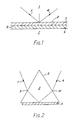
- FIG. 1 of the accompanying drawings Illustrated in Figure 1 of the accompanying drawings is a diagram of the equipment described in this paper.
- a beam 1 of light is applied from a laser source (not shown) onto an internal surface 2 of a glass body 3.
- a detector (not shown) monitors the internally reflected beam 4.
- Applied to the external surface 2 of glass body 3 is a thin film 5 of metal, for example gold or silver, and applied to the film 5 is a further thin film 6 of organic material containing antibodies.
- a sample 7 containing antigen is brought into contact with the antibody film 6 to thus cause a reaction between the antigen and the antibody. If binding occurs the refractive index of the layer 6 will change owing to the increased size of the antibody molecules and this change can be detected and measured using the surface plasmon resonance technique, as will now be explained.
- Surface plasmon resonance can be experimentally observed, in the arrangement of Figure 1, by varying the angle of the incident beam 1 and monitoring the intensity of the internally reflected beam 4. At a certain angle of incidence the parallel component of the light momentum will match with the dispersion for surface plasmons at the opposite surface 8 of the metal film. Provided that the thickness of metal film 5 is chosen correctly there will be an electromagnetic coupling between the glass/metal interface at surface 2 and the metal/antibody interface at surface 8 which results in surface plasmon resonance and thus an attenuation in the reflected beam 4 at that particular angle of incidence. Thus, as the angle of incidence of beam 1 is varied, surface plasmon resonance is observed as a sharp dip in the intensity of the internally reflected beam 4 at a particular angle of incidence.
- the angle of incidence at which resonance occurs is affected by the refractive index of the material against the metal film 5 - i.e. the antibody layer 6 - and the angle of incidence corresponding to resonance is thus a direct measure of the state of the reaction between the antibody and the antigen.
- Increased sensitivity can be obtained by choosing an angle of incidence half way down the reflectance dip curve, where the response is substantially linear, at the beginning of the antibody/antigen reaction, and then maintaining that angle of incidence fixed and observing changes in the intensity of the reflected beam 4 with time.
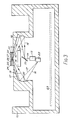
- FIG. 1 A diagram showing this arrangement is given in Figure 2 which is simply an experimental set up intended to demonstrate surface plasmon resonance.
- the prism is shown under reference 8 and has applied to its undersurface a thin film 5 of metal.
- Light 1 from a laser source (not shown) is incident on the prism where it is refracted at point 9 before entering the prism.
- the internally reflected beam 4 is likewise refracted (at point 10) upon exiting from the prism.
- the prism One problem with the prism is that, as the angle of incidence is changed, either by moving the source, or rotating the prism, or both, the point on surface 2 at which the incoming beam is incident moves. Because of inevitable variations in the metal film 5 and the coating 6 of antibody, the angle of incidence which results in resonance changes as this movement occurs, which in turn introduces a further variable factor into the measurement and thus makes comparisons between the initial, unbound, state and the bound state of the antibody layer 6 less accurate.
- reflective optics we mean that light from the light source is applied to the transparent block in which surface plasmon resonance is generated via at least one reflecting element such as a mirror.
- this block could be any shape because the refraction which this block inevitably introduces can either be ignored (because it is insignificant), or can be compensated for in the reflective optics.
- the block may take the form of a thin glass plate, such as are used for microscope slides, onto one surface of which is applied the metal and the antibody film in the manner illustrated in Figure 1. Incoming light is applied to the opposite surface and refracts through it at the interface.
- the optics may be tailored for any reasonable shape of glass including, as has been ment oned, flat plates, or prisms, and may by the same token be used in conjunction with the hemicylindrical and hemispherical blocks used in the apparatus described in our corresponding European Patent Application 0305109, or in conjunction with the optical waveguides (e.g. fibre optics) described in our corresponding European Patent Application 89300544.7 dated the 20th January 1989.
- the reflecting element is preferably such as to bring the light to a focus at the point of incidence on the glass/metal interface.
- the input beam effectively becomes several beams incident upon the glass/metal interface over a range of angles.
- the arrangment is such that the range of angles span the angle of dip corresponding to surface plasmon resonance.
- the corresponding internally reflected beam is likewise effectively several beams and may be monitored by a large area detector, or by an array of angularly spaced detectors positioned to collect the whole emergent beam.
- the detectors can encode the information from the whole of the dip within milliseconds.
- a single narrow beam we use just a single narrow beam, and means are provided for causing its angle of incidence at the glass/metal interface to scan across a range of angles of incidence such as is suitable for viewing the dip resulting from surface plasmon resonance. If the centre angle of such movement is chosen, for example, to be the angle at which surface plasmon resonance takes place, then the whole dip can be rapidly scanned.
- scanning means are used to scan the output of the radiation source backwards and forwards about a small arc before it is applied to the focussing means.
- the scanning means may be operable to cause a continuous 360 o sweep of the output of the radiation source - somewhat in the manner of the rotating light from a lighthouse - and to mask off all but a small arc of this sweep, which small arc is thence applied to the focussing means.
- the focussing means is operable to ensure that the scanning beam is incident on the glass/metal interface at substantially the same point whatever the instantaneous scanning angle might be.
- the scanning means may, for example take the form of a plane mirror which is oscillated backwards and forwards at a frequency of, for example 50Hz.
- the scanning means may be such as to cause continuous rotation of the mirror at, for example, 50 r.p.s., thus resulting in the 360 o swept beam referred to above.
- the mirror may be moved by a suitable motor and mechanical interconnection. Suitable examples are synchronous motors, DC servo motors and the like.
- the circuitry associated with the motor outputs a strobe pulse so that the detector which looks at the output beam - i.e.
- the beam which has been internally reflected at the glass/metal interface - is able, at any one instance of time, to identify the particular angle of incidence at which the input light is incident at the glass/metal interface. It will be seen that the information in the input light about the SPR reflectance dip is not obtained on a spatial basis, but on a time basis by synchronising the scanning of the input beam with the information output from the detector to build up a "picture" of the dip as the reaction between the antigen and the antibody proceeds.
- the detector may take the form of a large area detector which is positioned to intercept the output beam whatever its angle of incidence. Since the detector would only have to provide an intensity reading, and not an indication of the beam x - y position, the detector can be implemented quite cheaply, for example, in the form of an amorphous silicon device.
- the mirror used to scan the input beam can additionally be used to cause the beam to scan in other planes to enable multiple tests to be carried out simultaneously.
- the scanning to move the beam about the SPR dip, as described above, is essentially a single-plane effect, the beam being incident at the glass/metal interface at a single point which is stationary. By moving the point of incidence, multiple tests can be carried out, in effect, simultaneously because the movement of the beam is very fast compared with the progress of the test or tests.
- the mirror is caused to scan additionally in a plane at right angles to the plane of scanning to produce, in effect, a second scanning movement.
- a line of incidence is produced, caused by the point of incidence moving along the line as the second scanning movement of the mirror takes place.
- further lines, parallel to the first can be scanned thus giving, in effect, two dimensional raster scanning of an area. All that is now necessary is to divide up the metal and antibody layers across the line or area being scanned to enable separate tests to be carried out at each such divided area. Depending upon the particular sample feeding arrangements used, this enables the effective simultaneous testing of a number of different analytes within a given specimen, or a number of separate specimens.
- the separate divided areas may each have the same antibody or may have different antibodies, and one or more may have no antibodies at all, to act as "reference" areas.
- the scanning arrangements may be such as to cause continuous scanning of the point of incidence across the line or area to be tested, in which case the circuitry associated with the apparatus will be designed to ascertain, on a time basis, just where the point of incidence is at any one time (and therefore which area is being tested) and relate this to the output of the detector.
- the scanning may be such as to cause the point of incidence to "hover" over each area to be tested for a time sufficient to enable scanning across the dip to be effected at that point before passing on to the next.
- the shaping of the reflecting element can additionally be carried out in order to compensate for other irregularities, in particular refraction, as the light enters the glass block, in order to ensure that the light is always incident on as near as possible a single spot on the glass/metal interface at which surface plasmon resonance occurs.
- the reflective surface will be generally concave with a shape close to parabolic. The exact shape, however, in two dimensions will be determined also by the nature and shape of the glass block, this shape being derived by suitable computer programming.
- a characteristic modulation may be impressed on the electromagnetic radiation so that synchronous detection may be used to ensure that signals at the detector relating to the desired reflected radiation are adequately distinguishable from those undesired output signals relating to extraneous radiation or other noise sources that can affect the detector. Such modulation is particularly desirable when using a single large-area detector.
- the layer applied to the metal film is described herein as an antibody layer for use in immunoassays, it will be seen that any sensitive layer whose refractive index changes upon an event occurring can be used to thus provide a sensitive detector having a wide variety of applications in the fields of biology, biochemistry and chemistry.
- the material comprising the sensitive layer may be specific to a particular entity within the sample or may be non-specific (i.e. may interact with several species of entity within the sample).
- recognition molecules such as the aforementioned antibodies which will specifically bind an analyte of interest within the sample, DNA/RNA probes which will bind with their complements in the sample liquid, or lectins, glycoproteins or enzyme substrates, all of which are capable of recognising and binding with the other partner in a bimolecular recognition pair.
- non-specific materials include hydrophobic materials, for example in the form of a monolayer of phospholipid-type molecules to capture amphipathic molecules, or hydrophilic materials which would capture polysaccharides.
- hydrophobic materials for example in the form of a monolayer of phospholipid-type molecules to capture amphipathic molecules, or hydrophilic materials which would capture polysaccharides.
- the surface of the metal film itself can form an effective non-specific binding material. Silver or gold surfaces will bind proteins or polynucleotides such as DNA or RNA without the need for any further coating and, in this case a separate sensitive layer is effectively dispensed with altogether, and the surface of the metal film used directly for the capture of entities within the sample to be tested.
- the metal film material is commonly silver or gold, usually applied by evaporation.
- the film needs to be as uniform as possible in order to cater for minute movement in the point of incidence of the incoming beam. It is assumed that a structured metal film will give the best resonance and there are various ways in which the glass body can be pretreated to improve the performance of the metal film and in particular to control the natural tendency of such films to form discontinuous islands:-
- Coating performance can also be improved by:-
- the apparatus comprises a glass slide 11 of transparent material such as glass or quartz attached on a housing 12.
- a source 13 of electromagnetic radiation produces a collimated input beam 14 of electromagnetic radiation.
- the frequency of the radiation must be such as to result in the generation of surface plasmon waves and in practice will be within or near the visible region.
- Suitable sources include a helium neon laser or an infra red diode laser, but an ordinary light source, with suitable filters and collimators could be used.
- a rotatable mirror 15 is used to scan the beam backwards and forwards between the limit positions shown by the beams 16, 17 whose ray patterns are traced through the apparatus. With the mirror in the position indicated by the solid line, the limit beam 16 results; with the mirror in the position indicated by the dotted line, the limit beam 17 results.
- the mirror is moved by a motor (not shown) energised in such a way as to cause the beam to continuously scan between the limit positions 16 and 17.
- the mirror 15 may be driven by a synchronous motor or DC servo motor or similar at a rotation speed typically of 50HZ giving a scan period in the millisecond region.
- the beam from the mirror 15 is reflected off a generally concave reflecting surface 18 and is incident at a point 19 on the upper surface of the slide 11.
- This upper surface is formed with a metal film layer on top of which is an antibody or other sensitive layer, arranged in the manner illustrated in Figure 1.
- the combined metal film/antibody layer is shown under reference 20. Radiation which is internally reflected at point 19 passes out of the slide and is reflected by a further generally concave reflecting surface 21 into a radiation sensitive detector 22 which gives an electrical output signal for analysis by associated circuitry mounted on a printed circuit board 23 within the housing.
- the reflective surfaces 18, 21 are formed by machining of the material, for example aluminium, of the housing 12. If the housing is not fabricated from a suitable material, the reflective surfaces 18,21 can, of course, be formed as separate elements attached to the housing. Diamond machining of aluminium results in a highly reflective surface whose shape can be tailored, under computer control, to give whatever optical characteristics are required of it.
- the layer 20 is restricted to a relatively small active zone about the point 19 and within a central hole provided in a circular disc 24 of absorbent material Overlying disc 24 are two further discs 25, 26 of non-absorbent material.
- a central aperture in upper disc 26 defines a well 27 into which a sample to be tested is placed.
- a central aperture in disc 25 is of a size to cause liquid in well 27 to travel through by capillary action into the active zone above layer 20.
- the thickness of disc 24 is such as to define a depth for the active zone such as to promote radially outwards movement of the sample liquid emerging from aperture 28 by capillary action.
- the absorbent disc 24 absorbs sample which has flowed past the active zone.
- the whole unit comprising slide 11, disc 24 and discs 25 and 26 is disposable so that a fresh unit, including layer 20 can be used for each test.
- a sample to be tested, and containing an antigen capable of binding with the antibody molecules in layer 20 is placed in the well 27 and passes through aperture 28 by capillary action. Emerging from aperture 28, the liquid sample commences to flow rapidly outwards in all directions towards the absorbent disc 24, passing as it does so the layer 20. The sample adjacent the layer 20 is thus being constantly replenished during the course of the test, which ensures maximum sensitivity.
- any antigen within the sample capable of binding with the antibody in layer 20 will do so, thus altering the refractive index of layer 20 as the reaction proceeds.
- This change in refractive index is continuously monitored during the test by directing at the point 19 the light beam from source 13. Provided that conditions are correct - in particular the angle of incidence at the point 19 is correct - the application of the light beam will result in the generation of a plasmon wave, thus extracting energy from the input beam and causing an attenuation in the intensity of the output beam at a particular angle of incidence.
- the mirror 15 is oscillated backwards and forwards as the test proceeds so as to cause the beam to scan between the limit positions 16, 17, as explained above.
- the circuitry controlling the mirror motor outputs a strobe signal to enable the detector 22 to identify the instantaneous angle at which the light is incident at the point 19, so that an accurate picture of the reflectance dip can be obtained.
- the initial reflective dip which is chosen for setting up the limit beams 16, 17 may be taken from the dip which results when some neutral or buffer solution is passed through the cell, or when the sample under test is passed through the cell but before any reaction thereof has taken place.
- the refractive index does not start to change immediately due to the antibody/antigen reaction.
- This centre angle may be chosen to be the actual angle of dip, or it may be an angle half way down the reflectance dip.
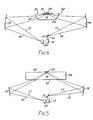
- Figure 3 shows the internal reflection needed to produce surface plasmon resonance being obtained from a thin glass slide 11, other geometrics are possible, and other methods of feeding the sample are also possible. Two alternative geometries are illustrated in Figures 4 and 5.
- the transparent block takes the form of a truncated prism 29, with the combined layer 20 applied to the base surface 30 of the prism.
- a glass slide 31 is optionally incorporated to provide a disposable assembly, as explained above.
- the slide, if used, is seated on the base surface 30 of the prism, using an optical coupling fluid.
- Light incident on the sloping input face 32 of the prism is subject to refraction and will result in the point 19 of incidence moving as the angle of the incoming beam is varied during scanning unless suitable measures are taken.
- these measures may take the form of suitable tailoring of the shape of the reflective surface 18 to ensure that, whatever the angle of incidence, the light is always incident at the glass/metal interface at a single spot.
- Figure 5 shows an arrangement in which the transparent block takes the form of a rectangular block 34 in which the rays enter and leave the block through the surface 35 opposite to the surface 36 at which internal reflection takes place.
- a disposable slide can be used, but this is not shown in Figure 5, the combined layer 20 being applied direct to the block.
- Refraction takes place at the glass/air interface at surface 35 and this may be compensated for in the manner explained above by tailoring the shape of reflective surfaces 18 and 19.
- the arrangement of Figure 5 is really no more than a version of the arrangement of Figure 3, but in which the glass slide 11 of Figure 3 is much thicker, thus exaggerating any errors due to refraction. In the case of a very thin glass slide, the errors associated with refraction may be small enough to be ignored but, if not, compensation can always be carried out, as explained above.
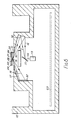
- Figure 6 shows an arrangement similar to that of Figure 3, but in which the output reflecting surface 21 and the small light detector 22 are replaced by a large area light detector 37, such as an amorphous silicon device.
- the detector may be positioned in any convenient position and has a radiation sensitive area which is large enough to encompass the full movement of the output beam.
- the output from the detector is synchronised with the scanning of mirror 15 so that the circuitry is able to identify what the detector is looking at at any one instance of time. For this reason, it is not necessary to provide the detector 37 with any x - y positional detection since the information in the beam is on a time basis, rather than a positional basis.
- the teaching of the present invention can also be applied to the apparatus described in our corresponding European Patent Applications 0305109 and 89300544.7, the disclosures of both of which are incorporated herein by this reference.
- the "input" reflective surface (reference 18) of the present invention would be used to bring the incoming beam to a focus at the input face of the optical waveguide (fibre optic).
- the mirror 15 will scan the beam 14 in substantially a single plane - that of the paper in Figures 3, 4, 5 and 6
- Means may also be provided for scanning the beam backwards and forwards into and out of the plane of the paper, but at a slower rate, so that the point 19 moves along a line extending at right angles to the plane of Figures 3, 4 and 5.
- This enables a single beam to sequentially scan a plurality of separate active areas each having a distinct sensitive layer thereon.
- the beam can scan continuously over the active area so formed, with appropriate synchronising signals to tell the detector what it is looking at, or the mirror may scan (in this direction only) in a series of discrete steps so as to hover briefly over each active area for sufficient time to take a reading. In this way several analytes within a single sample, or several separate samples, may be tested simultaneously for the same antibodies.
- each active area may have a different antibody, or some may be "reference" active areas.
- a two dimensional array of active areas is provided on the top surface of the slide 11 and means are provided for causing the point 19 of incidence to raster (two dimensional) scan the active areas line by line.
- raster two dimensional
- Such scanning is readily carried out by a single mirror or more likely, a mirror system to give the two dimensional scanning. As before, scanning may be continuous, or the beam may halt momentarily over each active area for sufficient time for a reading to be taken.
- scanning to obtain coverage of more than one active area is separate from the scanning used to alter the angle of incidence about the dip, although it may use the same mirror, moved in different planes. It should also be noted that scanning to cover multiple active areas may also be applied to the arrangements, such as those described in the aforementioned Patent Applications 8720854 and 8801807 in which a relatively wide input beam is focussed, by refractive or reflective optics, to the point 19 at which surface plasmon resonance occurs.
Landscapes
- Health & Medical Sciences (AREA)
- Life Sciences & Earth Sciences (AREA)
- Immunology (AREA)
- Chemical & Material Sciences (AREA)
- Engineering & Computer Science (AREA)
- Biochemistry (AREA)
- Urology & Nephrology (AREA)
- General Physics & Mathematics (AREA)
- Physics & Mathematics (AREA)
- Pathology (AREA)
- Analytical Chemistry (AREA)
- Biomedical Technology (AREA)
- General Health & Medical Sciences (AREA)
- Hematology (AREA)
- Molecular Biology (AREA)
- Medicinal Chemistry (AREA)
- Food Science & Technology (AREA)
- Biotechnology (AREA)
- Microbiology (AREA)
- Cell Biology (AREA)
- Investigating Or Analysing Materials By Optical Means (AREA)
Priority Applications (1)
| Application Number | Priority Date | Filing Date | Title |
|---|---|---|---|
| AT89304570T ATE91548T1 (de) | 1988-05-10 | 1989-05-05 | Biosensoren. |
Applications Claiming Priority (4)
| Application Number | Priority Date | Filing Date | Title |
|---|---|---|---|
| GB8811054 | 1988-05-10 | ||
| GB8811053 | 1988-05-10 | ||
| GB888811054A GB8811054D0 (en) | 1988-05-10 | 1988-05-10 | Biological sensors |
| GB888811053A GB8811053D0 (en) | 1988-05-10 | 1988-05-10 | Biological sensors |
Publications (2)
| Publication Number | Publication Date |
|---|---|
| EP0341927A1 true EP0341927A1 (fr) | 1989-11-15 |
| EP0341927B1 EP0341927B1 (fr) | 1993-07-14 |
Family
ID=26293877
Family Applications (1)
| Application Number | Title | Priority Date | Filing Date |
|---|---|---|---|
| EP89304570A Expired - Lifetime EP0341927B1 (fr) | 1988-05-10 | 1989-05-05 | Capteurs biologiques |
Country Status (7)
| Country | Link |
|---|---|
| US (1) | US5064619A (fr) |
| EP (1) | EP0341927B1 (fr) |
| JP (1) | JP2833778B2 (fr) |
| KR (1) | KR900018671A (fr) |
| CA (1) | CA1335539C (fr) |
| DE (1) | DE68907519T2 (fr) |
| FI (1) | FI96722C (fr) |
Cited By (28)
| Publication number | Priority date | Publication date | Assignee | Title |
|---|---|---|---|---|
| WO1992001217A1 (fr) * | 1990-07-04 | 1992-01-23 | Valtion Teknillinen Tutkimuskeskus | Procede d'execution de mesure de resonnance de plasmon de surface et detecteur s'utilisant dans ce procede |
| GB2247749A (en) * | 1990-09-05 | 1992-03-11 | Marconi Gec Ltd | Sensor utilising surface plasmon resonance |
| WO1993004357A1 (fr) * | 1991-08-20 | 1993-03-04 | Pharmacia Biosensor Ab | Methode de determination |
| EP0529999A3 (en) * | 1991-08-27 | 1993-05-26 | Donald W. Sting | Radiant energy spectroscopy system |
| WO1993014391A1 (fr) * | 1992-01-11 | 1993-07-22 | Fisons Plc | Dispositif d'analyse a angle d'incidence variable |
| WO1994000751A1 (fr) * | 1992-06-29 | 1994-01-06 | Pharmacia Biosensor Ab | Ameliorations apportees a des techniques d'analyse optique |
| FR2718849A1 (fr) * | 1994-04-14 | 1995-10-20 | Pasteur Sanofi Diagnostics | Procédé d'immunodosage de l'antithrombine III activée par un glycosaminoglycane, anticorps monoclonaux correspondants et leur procédé d'obtention. |
| WO1995029398A1 (fr) * | 1994-04-23 | 1995-11-02 | Fisons Plc | Dispositif d'analyse |
| EP0797090A3 (fr) * | 1996-03-19 | 1997-10-01 | Texas Instruments Incorporated | Captures integres a resonance de plasma de surface |
| WO1997044664A1 (fr) * | 1996-05-23 | 1997-11-27 | Unilever Plc | Ameliorations relatives aux tests d'immunodetection specifiques |
| EP0805347A3 (fr) * | 1996-04-30 | 1998-08-05 | Fuji Photo Film Co., Ltd. | Capteur de plasmons de surface |
| EP0836092A3 (fr) * | 1996-10-01 | 1998-09-16 | Texas Instruments Inc. | Capteur optique |
| DE19829086A1 (de) * | 1998-06-30 | 2000-01-13 | Univ Dresden Tech | Verfahren und Vorrichtung zur optischen Messung von ultradünnen Schichten |
| EP0982584A1 (fr) * | 1998-08-28 | 2000-03-01 | Perkin-Elmer Limited | Accessoire de spectromètre pour effectuer des mesures de réflexion totale atténuée |
| WO2001006236A1 (fr) * | 1999-07-15 | 2001-01-25 | Gpc Biotech Ag | Procede et dispositif d'analyse a rendement eleve de l'interaction moleculaire au moyen d'une resonance plasmonique de surface (spr) |
| US6180778B1 (en) | 1994-02-11 | 2001-01-30 | Qiagen Gmbh | Process for the separation of double-stranded/single-stranded nucleic acid structures |
| WO2003034046A1 (fr) * | 2001-10-17 | 2003-04-24 | Vir A/S | Capteur base sur la resonance des plasmons de surface |
| US6686208B2 (en) * | 1997-03-18 | 2004-02-03 | Institut Fur Chemo- Und Biosensorik Munster E.V. | Device and method for carrying out fluoresence immunotests |
| NL1022916C2 (nl) * | 2003-03-13 | 2004-09-14 | Ssens B V | Toestel en werkwijze voor onderzoek van een dunne laag opbouw gebruik makend van oppervlakte plasmon resonantie en inrichting en werkwijze voor het regelen van temperatuur. |
| WO2005050181A1 (fr) * | 2003-11-19 | 2005-06-02 | Beanor Oy | Procede et dispositif pour la mesure de la resonance plasmonique de surface |
| EP1835277A1 (fr) | 2006-03-15 | 2007-09-19 | Omron Corporation | Composant optique, capteur optique, capteur de plasmons de surface et dispositif de reconnaissance d'empreintes digitales |
| WO2009056875A1 (fr) | 2007-11-01 | 2009-05-07 | Attomarker Limited | Procédé d'optimisation de la sensibilité d'un ellipsomètre à plasmons de surface |
| CN100504287C (zh) * | 2006-07-24 | 2009-06-24 | 吴宝同 | 表面等离子共振测量装置和方法 |
| EP2181321A4 (fr) * | 2007-08-20 | 2011-10-19 | Korea Res Inst Of Bioscience | Capteur par résonance plasmonique de surface utilisant un miroir rotatif |
| CN102430439A (zh) * | 2007-10-01 | 2012-05-02 | 泰肯贸易股份公司 | 微型试管组件及其使用 |
| EP2437047A3 (fr) * | 2010-09-30 | 2012-10-24 | Precision Energy Services, Inc. | Capteur d'indice de réfraction pour l'analyse de fluides |
| US8411262B2 (en) | 2010-09-30 | 2013-04-02 | Precision Energy Services, Inc. | Downhole gas breakout sensor |
| CN105858593A (zh) * | 2016-04-05 | 2016-08-17 | 中国科学院半导体研究所 | 用于高灵敏生化检测的微型双端固支梁传感器的制作方法 |
Families Citing this family (94)
| Publication number | Priority date | Publication date | Assignee | Title |
|---|---|---|---|---|
| US4935346A (en) | 1986-08-13 | 1990-06-19 | Lifescan, Inc. | Minimum procedure system for the determination of analytes |
| GB8913474D0 (en) * | 1989-06-12 | 1989-08-02 | Amersham Int Plc | Assay method |
| US5489980A (en) * | 1992-03-18 | 1996-02-06 | Anthony; Michael | Apparatus for rapid and accurate analysis of the composition of samples |
| US5395587A (en) * | 1993-07-06 | 1995-03-07 | Smithkline Beecham Corporation | Surface plasmon resonance detector having collector for eluted ligate |
| GB9320305D0 (en) * | 1993-10-01 | 1993-11-17 | Kodak Ltd | Production of carriers for surface plasmin resonance |
| GB9320310D0 (en) * | 1993-10-01 | 1993-11-17 | Kodak Ltd | Production of carriers for surface plasmon resonance |
| US5955153A (en) * | 1993-10-01 | 1999-09-21 | Johnson & Johnson Clinical Diagnostics, Inc. | Production of carriers for surface plasmon resonance |
| JP3390063B2 (ja) * | 1993-10-25 | 2003-03-24 | 日本分光株式会社 | 高感度反射測定装置用の光学系 |
| US5485277A (en) * | 1994-07-26 | 1996-01-16 | Physical Optics Corporation | Surface plasmon resonance sensor and methods for the utilization thereof |
| US5814565A (en) * | 1995-02-23 | 1998-09-29 | University Of Utah Research Foundation | Integrated optic waveguide immunosensor |
| US5858799A (en) * | 1995-10-25 | 1999-01-12 | University Of Washington | Surface plasmon resonance chemical electrode |
| US5815278A (en) * | 1995-10-25 | 1998-09-29 | University Of Washington | Surface plasmon resonance light pipe sensing probe and related interface optics |
| US6356676B1 (en) | 1996-03-19 | 2002-03-12 | University Of Utah Research Foundation | Lens and associatable flow cell |
| US6108463A (en) * | 1996-03-19 | 2000-08-22 | University Of Utah Research Foundation | Lens and associatable flow cell |
| JP4043538B2 (ja) * | 1996-04-25 | 2008-02-06 | 富士フイルム株式会社 | 表面プラズモンセンサー |
| US5917607A (en) * | 1996-04-25 | 1999-06-29 | Fuji Photo Film Co., Ltd. | Surface plasmon sensor for multiple channel analysis |
| EP0990135A4 (fr) * | 1996-04-30 | 2000-04-26 | Metrika Inc | Procede et dispositif de mesure du rayonnement optique reflechi |
| US5852229A (en) * | 1996-05-29 | 1998-12-22 | Kimberly-Clark Worldwide, Inc. | Piezoelectric resonator chemical sensing device |
| US6020047A (en) * | 1996-09-04 | 2000-02-01 | Kimberly-Clark Worldwide, Inc. | Polymer films having a printed self-assembling monolayer |
| US5846843A (en) * | 1996-11-18 | 1998-12-08 | The University Of Toledo | Sensor using long range surface plasmon resonance with diffraction double-grating |
| US5922550A (en) * | 1996-12-18 | 1999-07-13 | Kimberly-Clark Worldwide, Inc. | Biosensing devices which produce diffraction images |
| US6048623A (en) * | 1996-12-18 | 2000-04-11 | Kimberly-Clark Worldwide, Inc. | Method of contact printing on gold coated films |
| US5776785A (en) * | 1996-12-30 | 1998-07-07 | Diagnostic Products Corporation | Method and apparatus for immunoassay using fluorescent induced surface plasma emission |
| US5898503A (en) * | 1997-03-19 | 1999-04-27 | Texas Instruments Incorporated | Surface plasmon resonance sensor with interchangeable optical element |
| US6180288B1 (en) | 1997-03-21 | 2001-01-30 | Kimberly-Clark Worldwide, Inc. | Gel sensors and method of use thereof |
| US6025189A (en) * | 1997-05-14 | 2000-02-15 | 3M Innovative Properties Company | Apparatus for reading a plurality of biological indicators |
| US6222619B1 (en) | 1997-09-18 | 2001-04-24 | University Of Utah Research Foundation | Diagnostic device and method |
| US6021240A (en) * | 1997-10-02 | 2000-02-01 | F&S, Inc. | Optical sensor activation device |
| US6343168B1 (en) | 1997-10-02 | 2002-01-29 | Luna Innovations, Inc. | Optical sensor arrangement |
| US6060256A (en) | 1997-12-16 | 2000-05-09 | Kimberly-Clark Worldwide, Inc. | Optical diffraction biosensor |
| IL137260A0 (en) | 1998-02-02 | 2001-07-24 | Signature Bioscience Inc | Method and apparatus for detecting molecular binding events |
| US6338968B1 (en) | 1998-02-02 | 2002-01-15 | Signature Bioscience, Inc. | Method and apparatus for detecting molecular binding events |
| US6395480B1 (en) | 1999-02-01 | 2002-05-28 | Signature Bioscience, Inc. | Computer program and database structure for detecting molecular binding events |
| US6275628B1 (en) | 1998-12-10 | 2001-08-14 | Luna Innovations, Inc. | Single-ended long period grating optical device |
| US6221579B1 (en) | 1998-12-11 | 2001-04-24 | Kimberly-Clark Worldwide, Inc. | Patterned binding of functionalized microspheres for optical diffraction-based biosensors |
| US6579673B2 (en) | 1998-12-17 | 2003-06-17 | Kimberly-Clark Worldwide, Inc. | Patterned deposition of antibody binding protein for optical diffraction-based biosensors |
| US6480282B1 (en) | 1999-05-06 | 2002-11-12 | University Of Washington | Capillary surface plasmon resonance sensors and multisensors |
| JP2001066248A (ja) * | 1999-08-26 | 2001-03-16 | Fuji Photo Film Co Ltd | 表面プラズモンセンサー |
| US7167615B1 (en) | 1999-11-05 | 2007-01-23 | Board Of Regents, The University Of Texas System | Resonant waveguide-grating filters and sensors and methods for making and using same |
| US6458326B1 (en) | 1999-11-24 | 2002-10-01 | Home Diagnostics, Inc. | Protective test strip platform |
| US6399295B1 (en) | 1999-12-17 | 2002-06-04 | Kimberly-Clark Worldwide, Inc. | Use of wicking agent to eliminate wash steps for optical diffraction-based biosensors |
| US7198939B2 (en) * | 2000-01-28 | 2007-04-03 | Agilent Technologies, Inc. | Apparatus for interrogating an addressable array |
| US6728429B1 (en) | 2000-02-16 | 2004-04-27 | Biotell, Inc. | Optical detection |
| US6576430B1 (en) * | 2000-11-20 | 2003-06-10 | Becton, Dickinson And Company | Detection of ligands by refractive surface methods |
| US6525330B2 (en) | 2001-02-28 | 2003-02-25 | Home Diagnostics, Inc. | Method of strip insertion detection |
| US6562625B2 (en) | 2001-02-28 | 2003-05-13 | Home Diagnostics, Inc. | Distinguishing test types through spectral analysis |
| US6885454B2 (en) * | 2001-03-28 | 2005-04-26 | Fuji Photo Film Co., Ltd. | Measuring apparatus |
| US7283707B1 (en) | 2001-07-25 | 2007-10-16 | Oewaves, Inc. | Evanescently coupling light between waveguides and whispering-gallery mode optical resonators |
| US6853479B1 (en) | 2001-08-30 | 2005-02-08 | Oewaves, Inc. | Apparatus and method for coupling light between an optical resonator and a semiconductor chip with a minimum number of components and alignment steps |
| US7300798B2 (en) * | 2001-10-18 | 2007-11-27 | Agilent Technologies, Inc. | Chemical arrays |
| US7102752B2 (en) | 2001-12-11 | 2006-09-05 | Kimberly-Clark Worldwide, Inc. | Systems to view and analyze the results from diffraction-based diagnostics |
| US7098041B2 (en) | 2001-12-11 | 2006-08-29 | Kimberly-Clark Worldwide, Inc. | Methods to view and analyze the results from diffraction-based diagnostics |
| US8367013B2 (en) | 2001-12-24 | 2013-02-05 | Kimberly-Clark Worldwide, Inc. | Reading device, method, and system for conducting lateral flow assays |
| US20030119203A1 (en) | 2001-12-24 | 2003-06-26 | Kimberly-Clark Worldwide, Inc. | Lateral flow assay devices and methods for conducting assays |
| JP4173725B2 (ja) * | 2001-12-25 | 2008-10-29 | 富士フイルム株式会社 | エバネッセント波を利用したセンサー |
| US6879752B1 (en) | 2002-04-03 | 2005-04-12 | Oewaves, Inc. | Film spacer for setting the gap between an optical coupler and a whispering-gallery mode optical resonator |
| US6791690B2 (en) * | 2002-04-30 | 2004-09-14 | Agilent Technologies, Inc. | Reading dry chemical arrays |
| US7223534B2 (en) | 2002-05-03 | 2007-05-29 | Kimberly-Clark Worldwide, Inc. | Diffraction-based diagnostic devices |
| US7485453B2 (en) * | 2002-05-03 | 2009-02-03 | Kimberly-Clark Worldwide, Inc. | Diffraction-based diagnostic devices |
| US7214530B2 (en) * | 2002-05-03 | 2007-05-08 | Kimberly-Clark Worldwide, Inc. | Biomolecule diagnostic devices and method for producing biomolecule diagnostic devices |
| US7223368B2 (en) | 2002-05-03 | 2007-05-29 | Kimberly-Clark Worldwide, Inc. | Diffraction-based diagnostic devices |
| US7118855B2 (en) * | 2002-05-03 | 2006-10-10 | Kimberly-Clark Worldwide, Inc. | Diffraction-based diagnostic devices |
| US7771922B2 (en) | 2002-05-03 | 2010-08-10 | Kimberly-Clark Worldwide, Inc. | Biomolecule diagnostic device |
| US7091049B2 (en) | 2002-06-26 | 2006-08-15 | Kimberly-Clark Worldwide, Inc. | Enhanced diffraction-based biosensor devices |
| US7314763B2 (en) | 2002-08-27 | 2008-01-01 | Kimberly-Clark Worldwide, Inc. | Fluidics-based assay devices |
| US7432105B2 (en) | 2002-08-27 | 2008-10-07 | Kimberly-Clark Worldwide, Inc. | Self-calibration system for a magnetic binding assay |
| US7285424B2 (en) | 2002-08-27 | 2007-10-23 | Kimberly-Clark Worldwide, Inc. | Membrane-based assay devices |
| US7169550B2 (en) * | 2002-09-26 | 2007-01-30 | Kimberly-Clark Worldwide, Inc. | Diffraction-based diagnostic devices |
| US7781172B2 (en) | 2003-11-21 | 2010-08-24 | Kimberly-Clark Worldwide, Inc. | Method for extending the dynamic detection range of assay devices |
| US6885455B2 (en) * | 2002-11-22 | 2005-04-26 | Dwight U. Bartholomew | Self-calibration of an optical-based sensor using a total internal reflection (TIR) signature |
| US7247500B2 (en) | 2002-12-19 | 2007-07-24 | Kimberly-Clark Worldwide, Inc. | Reduction of the hook effect in membrane-based assay devices |
| US20040197819A1 (en) | 2003-04-03 | 2004-10-07 | Kimberly-Clark Worldwide, Inc. | Assay devices that utilize hollow particles |
| US7851209B2 (en) | 2003-04-03 | 2010-12-14 | Kimberly-Clark Worldwide, Inc. | Reduction of the hook effect in assay devices |
| JP2005016963A (ja) * | 2003-06-23 | 2005-01-20 | Canon Inc | 化学センサ、化学センサ装置 |
| US20050112703A1 (en) | 2003-11-21 | 2005-05-26 | Kimberly-Clark Worldwide, Inc. | Membrane-based lateral flow assay devices that utilize phosphorescent detection |
| US7943395B2 (en) | 2003-11-21 | 2011-05-17 | Kimberly-Clark Worldwide, Inc. | Extension of the dynamic detection range of assay devices |
| US7713748B2 (en) | 2003-11-21 | 2010-05-11 | Kimberly-Clark Worldwide, Inc. | Method of reducing the sensitivity of assay devices |
| US7943089B2 (en) | 2003-12-19 | 2011-05-17 | Kimberly-Clark Worldwide, Inc. | Laminated assay devices |
| US7521226B2 (en) | 2004-06-30 | 2009-04-21 | Kimberly-Clark Worldwide, Inc. | One-step enzymatic and amine detection technique |
| KR100668323B1 (ko) * | 2005-01-19 | 2007-01-12 | 삼성전자주식회사 | 표면 플라즈몬 공명을 이용한 휴대용 바이오칩 스캐너 |
| JP4515927B2 (ja) * | 2005-01-25 | 2010-08-04 | 日本分光株式会社 | 全反射測定装置 |
| US7300631B2 (en) | 2005-05-02 | 2007-11-27 | Bioscale, Inc. | Method and apparatus for detection of analyte using a flexural plate wave device and magnetic particles |
| US7749445B2 (en) | 2005-05-02 | 2010-07-06 | Bioscale, Inc. | Method and apparatus for analyzing bioprocess fluids |
| US7648844B2 (en) | 2005-05-02 | 2010-01-19 | Bioscale, Inc. | Method and apparatus for detection of analyte using an acoustic device |
| US7611908B2 (en) | 2005-05-02 | 2009-11-03 | Bioscale, Inc. | Method and apparatus for therapeutic drug monitoring using an acoustic device |
| US7879619B2 (en) * | 2005-10-07 | 2011-02-01 | Tianwei Jing | Apparatus for detecting one or more substances and method of detecting a substance |
| JP2008102117A (ja) * | 2006-09-21 | 2008-05-01 | Fujifilm Corp | 表面プラズモン増強蛍光センサおよび蛍光検出方法 |
| US20090213383A1 (en) * | 2006-10-06 | 2009-08-27 | Nguyen Ly | Apparatus and method for detecting one or more substances |
| JP2009047436A (ja) * | 2007-08-13 | 2009-03-05 | Atago:Kk | 屈折計 |
| WO2009033056A1 (fr) | 2007-09-06 | 2009-03-12 | Bioscale, Inc. | Surfaces de détection réutilisables et procédés pour leur utilisation |
| JP2010025580A (ja) * | 2008-07-15 | 2010-02-04 | Olympus Corp | 光学ユニット |
| US9285516B2 (en) | 2010-08-02 | 2016-03-15 | Avinash Girish Bhardwaj | Actuator motion control mechanism for a concave mirror |
| US9006686B2 (en) | 2010-09-30 | 2015-04-14 | Konica Minolta Holdings, Inc. | Surface plasmon resonance fluorescence analysis device and surface plasmon resonance fluorescence analysis method |
| US10768108B2 (en) | 2011-09-28 | 2020-09-08 | Ge Healthcare Bio-Sciences Ab | Surface plasmon resonance biosensor system |
Citations (4)
| Publication number | Priority date | Publication date | Assignee | Title |
|---|---|---|---|---|
| US3645631A (en) * | 1970-05-05 | 1972-02-29 | Gte Sylvania Inc | Apparatus and method for measuring the carrier concentration of semiconductor materials |
| US4297032A (en) * | 1980-02-14 | 1981-10-27 | The United States Of America As Represented By The Secretary Of The Navy | Dark field surface inspection illumination technique |
| GB2173895A (en) * | 1985-04-12 | 1986-10-22 | Plessey Co Plc | Optical assay |
| EP0305109A1 (fr) * | 1987-08-22 | 1989-03-01 | AMERSHAM INTERNATIONAL plc | Senseurs biologiques |
Family Cites Families (6)
| Publication number | Priority date | Publication date | Assignee | Title |
|---|---|---|---|---|
| GB8509491D0 (en) * | 1985-04-12 | 1985-05-15 | Plessey Co Plc | Optic waveguide biosensors |
| JPS6147382A (ja) * | 1985-06-18 | 1986-03-07 | 株式会社ブリヂストン | 配管取付用パネル |
| JPS6382346A (ja) * | 1986-09-26 | 1988-04-13 | Shimadzu Corp | 溶液試料測定装置 |
| GB2197065A (en) * | 1986-11-03 | 1988-05-11 | Stc Plc | Optical sensor device |
| NL8700851A (nl) * | 1987-04-10 | 1988-11-01 | Tno | Werkwijze en inrichting voor het detecteren van zeer lage concentraties van een in een meetmedium aanwezige chemische component onder toepassing van oppervlakte-plasmonresonantie en elektrochemisch gestimuleerde adsorptie. |
| AU604364B2 (en) * | 1987-08-13 | 1990-12-13 | Dow Chemical Company, The | Sulfur dioxide removal from gas streams using hydroxyalkyl substituted piperazinones |
-
1989
- 1989-05-05 DE DE89304570T patent/DE68907519T2/de not_active Expired - Lifetime
- 1989-05-05 EP EP89304570A patent/EP0341927B1/fr not_active Expired - Lifetime
- 1989-05-08 CA CA000598945A patent/CA1335539C/fr not_active Expired - Fee Related
- 1989-05-09 FI FI892225A patent/FI96722C/fi not_active IP Right Cessation
- 1989-05-10 KR KR1019890006239A patent/KR900018671A/ko not_active Withdrawn
- 1989-05-10 JP JP1117159A patent/JP2833778B2/ja not_active Expired - Lifetime
- 1989-05-10 US US07/350,034 patent/US5064619A/en not_active Expired - Lifetime
Patent Citations (4)
| Publication number | Priority date | Publication date | Assignee | Title |
|---|---|---|---|---|
| US3645631A (en) * | 1970-05-05 | 1972-02-29 | Gte Sylvania Inc | Apparatus and method for measuring the carrier concentration of semiconductor materials |
| US4297032A (en) * | 1980-02-14 | 1981-10-27 | The United States Of America As Represented By The Secretary Of The Navy | Dark field surface inspection illumination technique |
| GB2173895A (en) * | 1985-04-12 | 1986-10-22 | Plessey Co Plc | Optical assay |
| EP0305109A1 (fr) * | 1987-08-22 | 1989-03-01 | AMERSHAM INTERNATIONAL plc | Senseurs biologiques |
Non-Patent Citations (4)
| Title |
|---|
| OPTICS COMMUNICATIONS, vol. 59, no. 5/6, 1st October 1986, pages 361-365, Elsevier Science Publishers B.V. (North-Holland Physics Publishing Division), Amsterdam, NL; K. ODA et al.: "Instantaneous observation of angular scan-attenuated total reflection spectra" * |
| PATENT ABSTRACTS OF JAPAN, vol. 12, no. 88 (P-678)[2935], 23rd March 1988, page 4 P 678; & JP-A-62 220 834 (TOSHIBA CORP.) 29-09-1987 * |
| REVIEW OF SCIENTIFIC INSTRUMENTS, vol. 43, no. 6, June 1972, pages 925-928; K.W. BEACH et al.: "A one-dimensional focusing critical angle refractometer for mass transfer studies" * |
| SENSORS AND ACTUATORS, vol. 4, 1983, pages 299-304, Elsevier Sequoia, NL; B. LIEDBERG et al.: "Surface plasmon resonance for gas detection and biosensing" * |
Cited By (45)
| Publication number | Priority date | Publication date | Assignee | Title |
|---|---|---|---|---|
| WO1992001217A1 (fr) * | 1990-07-04 | 1992-01-23 | Valtion Teknillinen Tutkimuskeskus | Procede d'execution de mesure de resonnance de plasmon de surface et detecteur s'utilisant dans ce procede |
| US5322798A (en) * | 1990-07-04 | 1994-06-21 | Valtion Teknillinen Tutkimuskeskus | Method for carrying out surface plasmon resonance measurement and sensor for use in the method |
| GB2247749A (en) * | 1990-09-05 | 1992-03-11 | Marconi Gec Ltd | Sensor utilising surface plasmon resonance |
| WO1993004357A1 (fr) * | 1991-08-20 | 1993-03-04 | Pharmacia Biosensor Ab | Methode de determination |
| US5573956A (en) * | 1991-08-20 | 1996-11-12 | Hanning; Anders | Assay method based upon refractive index changes at a solid optical surface |
| EP0529999A3 (en) * | 1991-08-27 | 1993-05-26 | Donald W. Sting | Radiant energy spectroscopy system |
| US5491556A (en) * | 1992-01-11 | 1996-02-13 | Fisons, Plc | Analytical device with variable angle of incidence |
| WO1993014391A1 (fr) * | 1992-01-11 | 1993-07-22 | Fisons Plc | Dispositif d'analyse a angle d'incidence variable |
| WO1994000751A1 (fr) * | 1992-06-29 | 1994-01-06 | Pharmacia Biosensor Ab | Ameliorations apportees a des techniques d'analyse optique |
| US5641640A (en) * | 1992-06-29 | 1997-06-24 | Biacore Ab | Method of assaying for an analyte using surface plasmon resonance |
| US6946250B2 (en) | 1994-02-11 | 2005-09-20 | Qiagen Gmbh | Process for the separation of double-stranded/single-stranded nucleic acid structures |
| US6180778B1 (en) | 1994-02-11 | 2001-01-30 | Qiagen Gmbh | Process for the separation of double-stranded/single-stranded nucleic acid structures |
| WO1995028644A1 (fr) * | 1994-04-14 | 1995-10-26 | Pasteur Sanofi Diagnostics | Procede d'immunodosage de l'antithrombine iii activee par un glycosaminoglycane, anticorps monoclonaux correspondants et leur procede d'obtention |
| FR2718849A1 (fr) * | 1994-04-14 | 1995-10-20 | Pasteur Sanofi Diagnostics | Procédé d'immunodosage de l'antithrombine III activée par un glycosaminoglycane, anticorps monoclonaux correspondants et leur procédé d'obtention. |
| US5891647A (en) * | 1994-04-14 | 1999-04-06 | Pasteur Sanofi Diagnostics | Method for the immunoassay of antithrombin III activated by a glycosaminoglycan, corresponding monoclonal antibodies and method for obtaining them |
| WO1995029398A1 (fr) * | 1994-04-23 | 1995-11-02 | Fisons Plc | Dispositif d'analyse |
| EP0797090A3 (fr) * | 1996-03-19 | 1997-10-01 | Texas Instruments Incorporated | Captures integres a resonance de plasma de surface |
| US5912456A (en) * | 1996-03-19 | 1999-06-15 | Texas Instruments Incorporated | Integrally formed surface plasmon resonance sensor |
| EP0805347A3 (fr) * | 1996-04-30 | 1998-08-05 | Fuji Photo Film Co., Ltd. | Capteur de plasmons de surface |
| US5907408A (en) * | 1996-04-30 | 1999-05-25 | Fuji Photo Film Co., Ltd. | Surface plasmon sensor |
| WO1997044664A1 (fr) * | 1996-05-23 | 1997-11-27 | Unilever Plc | Ameliorations relatives aux tests d'immunodetection specifiques |
| US6097479A (en) * | 1996-10-01 | 2000-08-01 | Texas Instruments Incorporated | Critical angle sensor |
| EP0836092A3 (fr) * | 1996-10-01 | 1998-09-16 | Texas Instruments Inc. | Capteur optique |
| US6686208B2 (en) * | 1997-03-18 | 2004-02-03 | Institut Fur Chemo- Und Biosensorik Munster E.V. | Device and method for carrying out fluoresence immunotests |
| DE19829086A1 (de) * | 1998-06-30 | 2000-01-13 | Univ Dresden Tech | Verfahren und Vorrichtung zur optischen Messung von ultradünnen Schichten |
| DE19829086C2 (de) * | 1998-06-30 | 2001-10-31 | Univ Dresden Tech | Verfahren zur optischen Bestimmung von chemischen und physikalischen Eigenschaften von ultradünnen Schichten und Vorrichtung zur Durchführung des Verfahrens |
| US6414311B1 (en) | 1998-08-28 | 2002-07-02 | Wellesley International C.V. | Spectrometer accessory for carrying out attenuated total reflectance measurements |
| EP0982584A1 (fr) * | 1998-08-28 | 2000-03-01 | Perkin-Elmer Limited | Accessoire de spectromètre pour effectuer des mesures de réflexion totale atténuée |
| WO2001006236A1 (fr) * | 1999-07-15 | 2001-01-25 | Gpc Biotech Ag | Procede et dispositif d'analyse a rendement eleve de l'interaction moleculaire au moyen d'une resonance plasmonique de surface (spr) |
| WO2003034046A1 (fr) * | 2001-10-17 | 2003-04-24 | Vir A/S | Capteur base sur la resonance des plasmons de surface |
| NL1022916C2 (nl) * | 2003-03-13 | 2004-09-14 | Ssens B V | Toestel en werkwijze voor onderzoek van een dunne laag opbouw gebruik makend van oppervlakte plasmon resonantie en inrichting en werkwijze voor het regelen van temperatuur. |
| CN1894576B (zh) * | 2003-11-19 | 2010-04-28 | 比恩诺尔股份公司 | 用于执行表面等离子共振测量的方法和装置 |
| WO2005050181A1 (fr) * | 2003-11-19 | 2005-06-02 | Beanor Oy | Procede et dispositif pour la mesure de la resonance plasmonique de surface |
| US7701582B2 (en) | 2003-11-19 | 2010-04-20 | Beanor Oy | Method and device for carrying out surface plasmon resonance measurement |
| EP1835277A1 (fr) | 2006-03-15 | 2007-09-19 | Omron Corporation | Composant optique, capteur optique, capteur de plasmons de surface et dispositif de reconnaissance d'empreintes digitales |
| US7692795B2 (en) | 2006-03-15 | 2010-04-06 | Omron Corporation | Optical component, optical sensor, surface plasmon sensor and fingerprint recognition device |
| CN100504287C (zh) * | 2006-07-24 | 2009-06-24 | 吴宝同 | 表面等离子共振测量装置和方法 |
| EP2181321A4 (fr) * | 2007-08-20 | 2011-10-19 | Korea Res Inst Of Bioscience | Capteur par résonance plasmonique de surface utilisant un miroir rotatif |
| CN102430439A (zh) * | 2007-10-01 | 2012-05-02 | 泰肯贸易股份公司 | 微型试管组件及其使用 |
| CN102430439B (zh) * | 2007-10-01 | 2015-04-01 | 泰肯贸易股份公司 | 微型试管组件及其使用 |
| WO2009056875A1 (fr) | 2007-11-01 | 2009-05-07 | Attomarker Limited | Procédé d'optimisation de la sensibilité d'un ellipsomètre à plasmons de surface |
| EP2437047A3 (fr) * | 2010-09-30 | 2012-10-24 | Precision Energy Services, Inc. | Capteur d'indice de réfraction pour l'analyse de fluides |
| US8411262B2 (en) | 2010-09-30 | 2013-04-02 | Precision Energy Services, Inc. | Downhole gas breakout sensor |
| US8542353B2 (en) | 2010-09-30 | 2013-09-24 | Precision Energy Services, Inc. | Refractive index sensor for fluid analysis |
| CN105858593A (zh) * | 2016-04-05 | 2016-08-17 | 中国科学院半导体研究所 | 用于高灵敏生化检测的微型双端固支梁传感器的制作方法 |
Also Published As
| Publication number | Publication date |
|---|---|
| JP2833778B2 (ja) | 1998-12-09 |
| FI892225A7 (fi) | 1989-11-11 |
| EP0341927B1 (fr) | 1993-07-14 |
| DE68907519D1 (de) | 1993-08-19 |
| FI96722C (fi) | 1996-08-12 |
| FI96722B (fi) | 1996-04-30 |
| US5064619A (en) | 1991-11-12 |
| KR900018671A (ko) | 1990-12-22 |
| FI892225A0 (fi) | 1989-05-09 |
| DE68907519T2 (de) | 1993-10-21 |
| JPH02103469A (ja) | 1990-04-16 |
| CA1335539C (fr) | 1995-05-16 |
Similar Documents
| Publication | Publication Date | Title |
|---|---|---|
| EP0341927B1 (fr) | Capteurs biologiques | |
| EP0305109B1 (fr) | Senseurs biologiques | |
| EP0343826B1 (fr) | Capteurs biologiques | |
| EP0326291B1 (fr) | Capteur biologique | |
| US5055265A (en) | Biological sensors | |
| US5035863A (en) | Surface plasmon resonance sensors | |
| US6239876B1 (en) | Optical detector device | |
| US6795192B2 (en) | SPR sensor and SPR sensor array | |
| US6628376B1 (en) | Method of examining biological, biochemical, and chemical characteristics of a medium and apparatus for its embodiment | |
| WO1992005426A1 (fr) | Detecteurs biologiques | |
| JP3399804B2 (ja) | 表面プラズモンセンサー | |
| EP0575132A1 (fr) | Dispositif de mesure optique | |
| JPH06500636A (ja) | 化学、生化学および生物学的な測定試料の特異物質を選択的に検出する光学的な方法 | |
| US6788415B2 (en) | Turntable measuring apparatus utilizing attenuated total reflection | |
| JP2003042944A (ja) | 表面プラズモン共鳴センサ装置 | |
| JP2003042945A (ja) | 表面プラズモン共鳴センサ装置 | |
| JP2003042946A (ja) | 表面プラズモン共鳴センサ、及び該表面プラズモン共鳴センサを用いた表面プラズモン共鳴センサ装置 | |
| JP2003057172A (ja) | 表面プラズモン共鳴センサ装置 |
Legal Events
| Date | Code | Title | Description |
|---|---|---|---|
| PUAI | Public reference made under article 153(3) epc to a published international application that has entered the european phase |
Free format text: ORIGINAL CODE: 0009012 |
|
| AK | Designated contracting states |
Kind code of ref document: A1 Designated state(s): AT BE CH DE FR GB IT LI LU NL SE |
|
| 17P | Request for examination filed |
Effective date: 19900222 |
|
| 17Q | First examination report despatched |
Effective date: 19910423 |
|
| GRAA | (expected) grant |
Free format text: ORIGINAL CODE: 0009210 |
|
| AK | Designated contracting states |
Kind code of ref document: B1 Designated state(s): AT BE CH DE FR GB IT LI LU NL SE |
|
| PG25 | Lapsed in a contracting state [announced via postgrant information from national office to epo] |
Ref country code: IT Free format text: LAPSE BECAUSE OF FAILURE TO SUBMIT A TRANSLATION OF THE DESCRIPTION OR TO PAY THE FEE WITHIN THE PRE;WARNING: LAPSES OF ITALIAN PATENTS WITH EFFECTIVE DATE BEFORE 2007 MAY HAVE OCCURRED AT ANY TIME BEFORE 2007. THE CORRECT EFFECTIVE DATE MAY BE DIFFERENT FROM THE ONE RECORDED.SCRIBED TIME-LIMIT Effective date: 19930714 Ref country code: AT Effective date: 19930714 |
|
| REF | Corresponds to: |
Ref document number: 91548 Country of ref document: AT Date of ref document: 19930715 Kind code of ref document: T |
|
| REF | Corresponds to: |
Ref document number: 68907519 Country of ref document: DE Date of ref document: 19930819 |
|
| ET | Fr: translation filed | ||
| PLBE | No opposition filed within time limit |
Free format text: ORIGINAL CODE: 0009261 |
|
| STAA | Information on the status of an ep patent application or granted ep patent |
Free format text: STATUS: NO OPPOSITION FILED WITHIN TIME LIMIT |
|
| PG25 | Lapsed in a contracting state [announced via postgrant information from national office to epo] |
Ref country code: LU Free format text: LAPSE BECAUSE OF NON-PAYMENT OF DUE FEES Effective date: 19940531 |
|
| 26N | No opposition filed | ||
| EAL | Se: european patent in force in sweden |
Ref document number: 89304570.8 |
|
| PGFP | Annual fee paid to national office [announced via postgrant information from national office to epo] |
Ref country code: FR Payment date: 19980511 Year of fee payment: 10 |
|
| PGFP | Annual fee paid to national office [announced via postgrant information from national office to epo] |
Ref country code: NL Payment date: 19980531 Year of fee payment: 10 |
|
| PGFP | Annual fee paid to national office [announced via postgrant information from national office to epo] |
Ref country code: BE Payment date: 19980714 Year of fee payment: 10 |
|
| PG25 | Lapsed in a contracting state [announced via postgrant information from national office to epo] |
Ref country code: BE Free format text: LAPSE BECAUSE OF NON-PAYMENT OF DUE FEES Effective date: 19990531 |
|
| REG | Reference to a national code |
Ref country code: GB Ref legal event code: 732E |
|
| BERE | Be: lapsed |
Owner name: AMERSHAM INTERNATIONAL P.L.C. Effective date: 19990531 |
|
| PG25 | Lapsed in a contracting state [announced via postgrant information from national office to epo] |
Ref country code: NL Free format text: LAPSE BECAUSE OF NON-PAYMENT OF DUE FEES Effective date: 19991201 |
|
| PG25 | Lapsed in a contracting state [announced via postgrant information from national office to epo] |
Ref country code: FR Free format text: LAPSE BECAUSE OF NON-PAYMENT OF DUE FEES Effective date: 20000131 |
|
| NLV4 | Nl: lapsed or anulled due to non-payment of the annual fee |
Effective date: 19991201 |
|
| REG | Reference to a national code |
Ref country code: FR Ref legal event code: ST |
|
| REG | Reference to a national code |
Ref country code: CH Ref legal event code: PUE Owner name: NYCOMED AMERSHAM PLC TRANSFER- BIACORE AB Ref country code: CH Ref legal event code: PFA Free format text: AMERSHAM INTERNATIONAL PLC TRANSFER- NYCOMED AMERSHAM PLC |
|
| REG | Reference to a national code |
Ref country code: FR Ref legal event code: TP |
|
| REG | Reference to a national code |
Ref country code: GB Ref legal event code: IF02 |
|
| REG | Reference to a national code |
Ref country code: CH Ref legal event code: PUE Owner name: GE HEALTHCARE BIO-SCIENCES AB Free format text: BIACORE AB#RAPSGATAN 5#754 50 UPPSALA (SE) -TRANSFER TO- GE HEALTHCARE BIO-SCIENCES AB#BJOERKGATAN 30#751 84 UPPSALA (SE) Ref country code: CH Ref legal event code: NV Representative=s name: ISLER AND PEDRAZZINI AG |
|
| REG | Reference to a national code |
Ref country code: GB Ref legal event code: 732E |
|
| PGFP | Annual fee paid to national office [announced via postgrant information from national office to epo] |
Ref country code: CH Payment date: 20080530 Year of fee payment: 20 |
|
| PGFP | Annual fee paid to national office [announced via postgrant information from national office to epo] |
Ref country code: SE Payment date: 20080529 Year of fee payment: 20 Ref country code: DE Payment date: 20080630 Year of fee payment: 20 |
|
| PGFP | Annual fee paid to national office [announced via postgrant information from national office to epo] |
Ref country code: GB Payment date: 20080529 Year of fee payment: 20 |
|
| REG | Reference to a national code |
Ref country code: CH Ref legal event code: PL |
|
| REG | Reference to a national code |
Ref country code: GB Ref legal event code: PE20 Expiry date: 20090504 |
|
| EUG | Se: european patent has lapsed | ||
| PG25 | Lapsed in a contracting state [announced via postgrant information from national office to epo] |
Ref country code: GB Free format text: LAPSE BECAUSE OF EXPIRATION OF PROTECTION Effective date: 20090504 |