EP0341945A2 - Codeur d'interface pour angle d'arbre - Google Patents
Codeur d'interface pour angle d'arbre Download PDFInfo
- Publication number
- EP0341945A2 EP0341945A2 EP89304615A EP89304615A EP0341945A2 EP 0341945 A2 EP0341945 A2 EP 0341945A2 EP 89304615 A EP89304615 A EP 89304615A EP 89304615 A EP89304615 A EP 89304615A EP 0341945 A2 EP0341945 A2 EP 0341945A2
- Authority
- EP
- European Patent Office
- Prior art keywords
- signal
- byte
- frequency clock
- providing
- integrated circuit
- Prior art date
- Legal status (The legal status is an assumption and is not a legal conclusion. Google has not performed a legal analysis and makes no representation as to the accuracy of the status listed.)
- Granted
Links
Images


Classifications
-
- G—PHYSICS
- G01—MEASURING; TESTING
- G01S—RADIO DIRECTION-FINDING; RADIO NAVIGATION; DETERMINING DISTANCE OR VELOCITY BY USE OF RADIO WAVES; LOCATING OR PRESENCE-DETECTING BY USE OF THE REFLECTION OR RERADIATION OF RADIO WAVES; ANALOGOUS ARRANGEMENTS USING OTHER WAVES
- G01S7/00—Details of systems according to groups G01S13/00, G01S15/00, G01S17/00
- G01S7/02—Details of systems according to groups G01S13/00, G01S15/00, G01S17/00 of systems according to group G01S13/00
-
- G—PHYSICS
- G01—MEASURING; TESTING
- G01D—MEASURING NOT SPECIALLY ADAPTED FOR A SPECIFIC VARIABLE; ARRANGEMENTS FOR MEASURING TWO OR MORE VARIABLES NOT COVERED IN A SINGLE OTHER SUBCLASS; TARIFF METERING APPARATUS; MEASURING OR TESTING NOT OTHERWISE PROVIDED FOR
- G01D5/00—Mechanical means for transferring the output of a sensing member; Means for converting the output of a sensing member to another variable where the form or nature of the sensing member does not constrain the means for converting; Transducers not specially adapted for a specific variable
- G01D5/12—Mechanical means for transferring the output of a sensing member; Means for converting the output of a sensing member to another variable where the form or nature of the sensing member does not constrain the means for converting; Transducers not specially adapted for a specific variable using electric or magnetic means
- G01D5/244—Mechanical means for transferring the output of a sensing member; Means for converting the output of a sensing member to another variable where the form or nature of the sensing member does not constrain the means for converting; Transducers not specially adapted for a specific variable using electric or magnetic means influencing characteristics of pulses or pulse trains; generating pulses or pulse trains
- G01D5/245—Mechanical means for transferring the output of a sensing member; Means for converting the output of a sensing member to another variable where the form or nature of the sensing member does not constrain the means for converting; Transducers not specially adapted for a specific variable using electric or magnetic means influencing characteristics of pulses or pulse trains; generating pulses or pulse trains using a variable number of pulses in a train
- G01D5/2451—Incremental encoders
-
- G—PHYSICS
- G01—MEASURING; TESTING
- G01B—MEASURING LENGTH, THICKNESS OR SIMILAR LINEAR DIMENSIONS; MEASURING ANGLES; MEASURING AREAS; MEASURING IRREGULARITIES OF SURFACES OR CONTOURS
- G01B7/00—Measuring arrangements characterised by the use of electric or magnetic techniques
- G01B7/30—Measuring arrangements characterised by the use of electric or magnetic techniques for measuring angles or tapers; for testing the alignment of axes
Definitions
- the invention relates to shaft angle encoder interface apparatus, with particular reference to incremental shaft angle encoders having quadrature channel outputs.
- Shaft angle encoders are utilised to measure the angular position of a rotating shaft. For example, the angle of a rotating antenna shaft with respect to a reference point in a radar system is utilised to display radar targets at the appropriate display bearings.
- Such shaft angle encoders may be of the incremental optical type that provide quadrature square waves and a reference pulse which are decoded to indicate the shaft angle.
- the reference pulse may be utilised to provide an azimuthal reference at, for example, 0 from which shaft rotation is measured.
- the reference pulse occurs once every 360°.
- the quadrature square waves relate to the rotation of the shaft with respect to angular position and direction of rotation.
- the quadrature square waves are generated optically by a rotating code wheel in the optical shaft angle encoder.
- Two tracks of radial slits on the rotating code wheel generate the quadrature square waves.
- Each of the tracks is comprised of alternating slits and opaque areas of equal width, one track being displaced 90 with respect to the other track.
- Light passing through the slits on the rotating code wheel impinge upon photodetectors associated with each of the tracks, thereby generating voltages. Since the code wheel is rotating, the photodetectors receive alternating periods of light and dark thereby generating the quadrature square waves
- the reference pulse is generated by a slit on the rotating code wheel at a reference position.
- the amount of rotation can be determined by counting the number of transitions from zero to a positive voltage and the direction of rotation is decoded by processing the quadrature square waves.
- the angular position of the shaft is encoded by the shaft angle encoder as square waves out-of-phase with respect to each other by 90 ⁇ .
- These quadrature channel square waves require decoding to provide the angular resolution.
- Such shaft angle encoders require interface electronics to convert the quadrature square waves into a digital angle for use in the system.
- the digital angle may be utilised by the video system for positioning the radar targets at the proper bearings.
- the interface logic required to accomplish the decoding conversion from quadrature square wave channels to a digital angle utilising logic chips, such as gate arrays or discrete logic devices can be extensive, and hence very expensive, particularly with respect to determining the direction of rotation.
- integrated circuits are available for decoding quadrature channels when interfaced with a microprocessor. A chip of this type is available from the Hewlett Packard Company as the Quadrature Decoder Counter Interface IC denoted as the HCTL-2000.
- the HCTL-2000 decodes quadrature square waves and provides a 12 bit digital angle when interfaced with a microprocessor which provides control signals to the HCTL-2000.
- the use of the microprocessor is undesirable because of the excessive cost and board real estate required therefor.
- the microprocessor requires extensive source code assembly language preparation which must be downloaded into program memory. Since the microprocessor must be programmed to effect its control and decoding functions, the cost of the software and the cost of the microprocessor adds an undesired expense to the system.
- a further disadvantage of the quadrature channel decoding chip-microprocessor interface is that chips such as the HCTL-2000 have an internal inhibit mode that is automatically enabled during the time that the digital angle is read from the chip output.
- the inhibit logic latches the current angle preventing updating from the shaft angle encoder of the chip output angle.
- the digital angle from the shaft angle encoder may change during the inhibit mode, the output angle from the HCTL-2000 is not changed until the inhibit mode is reset.
- the display generally lags some incremental angular error behind the actual shaft position.
- the data is maintained stable during the readout period, the accuracy of the system is adversely affected since the data transfer rate of the system is reduced.
- HCTL-2000 up/down counter can continue to update the quadrature states. The information, however, is not made available until exiting from the inhibit mode. This may cause angle information data jumps rather than providing continuously updated data.
- the present invention utilises as defined in the appended claims and a state machine, preferably implemented by a programmable logic device (PLD), to control the quadrature channel decoding chip such as the HCTL-2000.
- the state machine provides an updated digital angle every data sample time thereby disabling the decoding chip inhibit mode.
- the angular data is updated at the fastest possible rate and the cost and amount of hardware required to transform the shaft angle encoder output into a digital angle is minimised.
- the invention minimises the system cost by utilising the state machine to drive the HCTL-2000 instead of the microprocessor for which the HCTL-2000 was designed.
- PLD's are less costly than microprocessors and do not require the writing of extensive source code programming as do microprocessors.
- the state machine provides an updated digital angle at a substantially faster rate than the microprocessor interfaces.
- the quadrature channel square wave outputs of the shaft angle encoder are illustrated.
- the output denoted as channel A leads the angular position by 45 and the output designated as channel B lags the angular position by 45 ⁇ .
- the channel B square wave output is in quadrature with the channel A square wave output.
- the channel A and channet B voltage levels represent four cyclically repeated states denoted as 1, 2, 3 and 4.
- state 1 channel A is binary ONE and channel B is binary ZERO.
- both channels are binary ONE.
- state 3 channel A is binary ZERO and channel B is binary ONE and in state 4, both channels are binary ZERO.
- the incremental position of the encoder is tracked by detecting transitions in the state and incrementing or decrementing an up/down counter to provide a digital readout of the angle.
- the direction of rotation is decoded by comparing the previous state to the current state and controlling the counter counter accordingly.
- the counter is controlled to count up for state transitions in the order 1, 2, 3, 4, 1, etc. and is controlled to count down for state transitions in the order 1, 4, 3, 2, 1, etc.
- Figure 1 also illustrates the reference pulse which is utilised to reset the up/down counter to zero.
- the reference pulse spans one cycle of the channel A and channel B square waves.
- the reference pulse is processed to provide a processed reference pulse as illustrated so that the angle is held at zero for one count instead of four counts.
- the chip includes a digital filter 10 to reduce noise and decode logic 11 to decode the quadrature square waves from the shaft angle encoder into a digital angle at output Do-D 1 .
- the quadrature square waves from the encoder are applied at CH A (channel A) and CH B, (channel B), respectively. to the digital filter 10 through Schmitt trigger inputs 12 and 13.
- the digital filter 10 is configured to provide a new output for each channel if the input level has had the same value on three consecutive rising clock edges.
- the channel A and channel B outputs from the filter 10 are applied to decode logic 11 directly and through respective D-flip-flops 14 and 15 so that the decode logic 11 receives the previous sampled state and the current sampled state. If the two states are different, the decode logic 11 provides a count signal CNT and an up/down signal UP/DN to a twelve-bit binary counter up/down counter 16. As discussed above with respect to Figure 1, the counter 16 is incremented or decremented when the previous sampled state of the quadrature square waves is different from the current state and the direction of count is controlled by comparing the states.
- the twelve bit angle output of the counter 16 is applied to a twelve-bit latch 17 which provides an eight-bit byte (high byte) and a four-bit byte (low byte) to an octal two-byte multiplexer buffer 18.
- the buffer 18 output Do-D 7 provides the resulting digital angle.
- the angle is read in two sequential bytes (high byte and low byte) to provide a twelve bit result.
- the output enable input ( OE) controls the chip readout and the select input (SEL) controls the readout of the high byte and the low byte.
- a clock signal CLK is applied through a Schmitt trigger input 19 to provide the clock input CK which controls the sampling of the OE and SEL lines as well as controlling the operation of the digital filter 10, the D-flip-flops 14 and 15, the counter 16 and the latch 17.
- the reference pulse from the shaft angle encoder is applied at RSTthrough a Schmitt trigger input 20 to reset the angle to zero. The reset pulse clears the counter 16 and the latch 17.
- the HCTL-2000 chip includes inhibit logic 21 for inhibiting data entry into the latch 17 when the buffer 18 is in the process of being read out. Thus, during this time, changes in the angle data in the counter 16 are not displayed.
- the inhibit logic 21 provides the inhibit signal to the latch 17 when UE-, SEL and CK are simultaneously low.
- the shaft angle encoder provides the CH A, CH B and RST signals.
- a microprocessor (not shown) provides CLK, SEL and OE and receives the sequentially provided high byte and low byte on the data lines Do-D 7 so as to format a twelve-bit digital angle.
- Software must be written for, and loaded into, the microprocessor to control providing and receiving these signals and to operate the HCTL-2000 in accordance with the timing diagram of Figure 3.
- Such software is complex, extensive and expensive and in addition the microprocessor imposes an undesirable expense and board real estate requirement on the system.
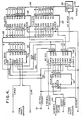
- the interface includes and HCTL-2000 chip 30 coupled to receive the lead and lag quadrature channel signals from the shaft angle encoder at pins 6 and 7 thereof.
- the CLK input to the HCTL-2000 is applied at pin 2 thereof from a 13 KHz clock source provided by the system at a terminal 31.
- These controls signals are generated by a state machine 32 preferably implemented by an EP310 PLD commercially available, for example, from the Altera Corporation.
- the EP310 also provides the reset pulse RS7to the HCTL-2000 at pin 5 thereof, in a manner to be described.
- the chip outputs of the HCTL-2000 Do-D 7 are provided at the output pins illustrated and are applied to an eight-bit parallel bus 33.
- the bus 33 is connected in parallel to the inputs of a high-byte latch 34 and to the inputs of a low-byte latch 35.
- the latches 34 and 35 sequentially receive the high byte and the low byte from the HCTL-2000 to assemble a twelve-bit digital angle on a bus 36.
- the latches 34 and 35 are preferably implemented by 74LS273 chips available, for example, from Texas Instruments, Incorporated.
- the latches 34 and 35 are controlled by the EP310 in a manner to be described.
- the digital angle output on the bus 36 is provided to the system under control of an azimuth ready signal AZREADY on a line 37.
- the interface output is schematically represented by an Angle Bus Out block 38 under control of the AZREADY signal to provide the interface angle on an output bus 39.
- the OE signal from the EP310 provides the azimuth ready signal so that bus reads are disabled during the time the HCTL-2000 is transferring the high and low bytes to the latches 34 and 35.
- the EP310 receives a 3.36 MHz system clock at pin 1 thereof and also receives the 13 KHz clock from the terminal 31 at pin 11 thereof.
- the 13 KHz clock is utilised as a READ signal by the EP310 to provide a digital angle sample.
- Pins 2 and 3 of the EP310 are connected to logic ONE for internal gating purposes.
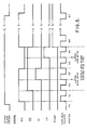
- the timing diagram of the EP310 is illustrated in Figure 5 and corresponds to the truth table set forth above. It will be appreciated, however, that the outputs of the EP310 include inversions that provide the outputs inverted with respect to the waveforms illustrated in Figure 5.
- the EP310 is controlled to operate in seven states S1-S7 and in a state PU (Power Up) when the system is first energised.
- a dummy variable RIDER is included to distinguish between the states S1 and S6.
- the state machine 32 enters state S1 under control of the 3.36 MHz clock when the 13 KHz READ signal goes high.
- state S1 the state machine 32 is programmed to output SEL low and OC, HI and LO high. With OE high.
- the HCTL-2000 outputs Do-D 1 are in the high impedance state.
- the state machine 32 is programmed to enter state S2.
- S2 SEL and OE are low and HI and LO are high.
- OE the outputs Do-D 7 of the HCTL-2000 are enabled. Since SEL is in the low state, the HCTL-2000 outputs the high byte onto the bus 33.
- the state machine 32 enters the state S3.
- the HI signal is changed to the low state and latches the high byte on the bus 33 into the latch 34.
- state S4 Upon the occurrence of the next high frequency clock pulse, state S4 is entered which changes the state of the SEL signal and returns the HI signal to high. With SEL and OE as issued by the EP310 to the HCTL-2000 during state S4, the low byte is placed on the Do-D 7 outputs of the HCTL-2000 and thus onto the bus 33.
- the next occurring high frequency clock pulse places the state machine 32 into state S5 for providing the LO pulse to the latch 35 thereby latching the low byte therein.
- the next occurring high frequency clock pulse advances the state machine 32 to the S6 state which turns off the LO signal as well as the OE signal thereby returning the HCTL-2000 outputs Do-D 1 to the high impedance state.
- the AZREADY signal on the line 37 is placed into its active state thereby permitting readout of the digital bus angle from the latches 34 and 35 onto the bus 39. It will be appreciated that during states S2-S5, when the latches 34 and 35 are being loaded, the AZREADY signal is in the inactive state, thereby disabling bus reads.
- the state machine 32 transitions from S6 to S7 and remains in state S7 until the next rising edge of the READ clock.
- READ occurs in state S7, the state machine 32 enters the S1 state to commence reading another sample of the digital angle.
- the state machine 32 On power up of the equipment, the state machine 32 is placed into the PU state and remains in this state until the first occurring rising edge of the 13 KHz READ clock. When READ occurs, the state machine 32 enters state S1.
- the reset pulse from the shaft angle encoder ( RSi ⁇ ) is processed by the EP310 via the 74LS164 to provide the RSTinstalle ( RSTq) to the HCTL-2000.
- the RST waveshaping is illustrated in Figure 6. It is appreciated that by the shift register action of the 74LS164 and the appropriate programming of the EP310, the shaft angle encoder reset pulse that spans four counts is converted to a reset pulse that spans one count and occurs at precisely 0 ⁇ . If the RST putse were not processed, the angle on Do-D 7 from the HCTL-2000 would be held at zero for four counts instead of one. Thus, with the reset pulse processing the azimuth count is zeroed every time the shaft rotates through 0 and then recommences counting thereafter.
- the invention utilises a state machine implemented by a programmable logic device to drive the HCTL-2000 in contrast to the prior art utilisation of a microprocessor.
- PLDs are less costly than microprocessors and do not require down loading of assembly language as do microprocessors. Additionally, microprocessors require far greater board real estate than do PLDs.
- the shaft angle encoder interface invention provides a twelve-bit digital angle from a shaft angle encoder with minimal cost and hardware.
- the present invention permits greater than 20% tolerance in the quadrature channels as compared to a tolerance of 12% as obtained in the prior art. This results from the high sampling rate obtained utilising the 3.36 MHz clock.
Landscapes
- Physics & Mathematics (AREA)
- General Physics & Mathematics (AREA)
- Engineering & Computer Science (AREA)
- Computer Networks & Wireless Communication (AREA)
- Radar, Positioning & Navigation (AREA)
- Remote Sensing (AREA)
- Transmission And Conversion Of Sensor Element Output (AREA)
- Analogue/Digital Conversion (AREA)
Applications Claiming Priority (2)
| Application Number | Priority Date | Filing Date | Title |
|---|---|---|---|
| US07/191,922 US4931792A (en) | 1988-05-09 | 1988-05-09 | Shaft angle encoder interface |
| US191922 | 1998-11-13 |
Publications (3)
| Publication Number | Publication Date |
|---|---|
| EP0341945A2 true EP0341945A2 (fr) | 1989-11-15 |
| EP0341945A3 EP0341945A3 (en) | 1990-08-01 |
| EP0341945B1 EP0341945B1 (fr) | 1992-09-16 |
Family
ID=22707467
Family Applications (1)
| Application Number | Title | Priority Date | Filing Date |
|---|---|---|---|
| EP89304615A Expired - Lifetime EP0341945B1 (fr) | 1988-05-09 | 1989-05-08 | Codeur d'interface pour angle d'arbre |
Country Status (6)
| Country | Link |
|---|---|
| US (1) | US4931792A (fr) |
| EP (1) | EP0341945B1 (fr) |
| JP (1) | JPH01307668A (fr) |
| KR (1) | KR930001726B1 (fr) |
| DE (1) | DE68902866T2 (fr) |
| DK (1) | DK222889A (fr) |
Cited By (3)
| Publication number | Priority date | Publication date | Assignee | Title |
|---|---|---|---|---|
| WO1997002515A1 (fr) * | 1995-07-03 | 1997-01-23 | Nsm Aktiengesellschaft | Procede et appareil de positionnement d'un moteur pas-a-pas pour un appareil de reproduction, d'enregistrement et/ou d'extraction de disques |
| DE102008031345A1 (de) * | 2008-07-02 | 2010-01-07 | Bayerische Motoren Werke Aktiengesellschaft | Auswerteeinheit, Verfahren zur Datenverarbeitung und KFZ mit Auswerteeinheit |
| CN112037501A (zh) * | 2020-08-31 | 2020-12-04 | 华中光电技术研究所(中国船舶重工集团公司第七一七研究所) | 一种基于fpga的多路轴角智能检测纠错和收发装置 |
Families Citing this family (4)
| Publication number | Priority date | Publication date | Assignee | Title |
|---|---|---|---|---|
| KR930003458B1 (ko) * | 1990-10-12 | 1993-04-29 | 삼성전자 주식회사 | 로보트의 절대위치 제어를 위한 카운터회로 |
| JP2720642B2 (ja) * | 1991-07-30 | 1998-03-04 | 三菱電機株式会社 | 多回転絶対値エンコーダ |
| TW256914B (en) * | 1994-05-27 | 1995-09-11 | Ibm | Servo-writing system for use in a data recording disk drive |
| FR2790322A1 (fr) * | 1999-02-26 | 2000-09-01 | Koninkl Philips Electronics Nv | Recepteur, circuit programmable et procede de calcul de filtres numeriques |
Family Cites Families (4)
| Publication number | Priority date | Publication date | Assignee | Title |
|---|---|---|---|---|
| US4558304A (en) * | 1983-02-24 | 1985-12-10 | Texas Instruments Incorporated | Incremental encoder synchronous decode circuit |
| US4714913A (en) * | 1985-07-16 | 1987-12-22 | Cohen Robert K | Quadrature phase signal processor |
| JPS6347612A (ja) * | 1986-08-13 | 1988-02-29 | Mitsutoyo Corp | 変位検出装置 |
| US4752846A (en) * | 1986-10-09 | 1988-06-21 | Hewlett-Packard Company | Tape drive system with tape position capture circuitry |
-
1988
- 1988-05-09 US US07/191,922 patent/US4931792A/en not_active Expired - Lifetime
- 1988-12-17 KR KR1019880016825A patent/KR930001726B1/ko not_active Expired - Fee Related
-
1989
- 1989-02-03 JP JP1025604A patent/JPH01307668A/ja active Pending
- 1989-05-05 DK DK222889A patent/DK222889A/da not_active Application Discontinuation
- 1989-05-08 DE DE8989304615T patent/DE68902866T2/de not_active Expired - Fee Related
- 1989-05-08 EP EP89304615A patent/EP0341945B1/fr not_active Expired - Lifetime
Cited By (5)
| Publication number | Priority date | Publication date | Assignee | Title |
|---|---|---|---|---|
| WO1997002515A1 (fr) * | 1995-07-03 | 1997-01-23 | Nsm Aktiengesellschaft | Procede et appareil de positionnement d'un moteur pas-a-pas pour un appareil de reproduction, d'enregistrement et/ou d'extraction de disques |
| US6020705A (en) * | 1995-07-03 | 2000-02-01 | Nsm Aktiengesellschaft | Process and equipment for positioning a step motor for a disk playback, recording and/or extracting machine |
| DE102008031345A1 (de) * | 2008-07-02 | 2010-01-07 | Bayerische Motoren Werke Aktiengesellschaft | Auswerteeinheit, Verfahren zur Datenverarbeitung und KFZ mit Auswerteeinheit |
| DE102008031345B4 (de) * | 2008-07-02 | 2016-03-10 | Bayerische Motoren Werke Aktiengesellschaft | Auswerteeinheit, Verfahren zur Datenverarbeitung und KFZ mit Auswerteeinheit |
| CN112037501A (zh) * | 2020-08-31 | 2020-12-04 | 华中光电技术研究所(中国船舶重工集团公司第七一七研究所) | 一种基于fpga的多路轴角智能检测纠错和收发装置 |
Also Published As
| Publication number | Publication date |
|---|---|
| JPH01307668A (ja) | 1989-12-12 |
| DK222889D0 (da) | 1989-05-05 |
| DE68902866D1 (de) | 1992-10-22 |
| EP0341945A3 (en) | 1990-08-01 |
| EP0341945B1 (fr) | 1992-09-16 |
| KR930001726B1 (ko) | 1993-03-12 |
| DK222889A (da) | 1989-11-10 |
| DE68902866T2 (de) | 1993-01-07 |
| KR890017551A (ko) | 1989-12-16 |
| US4931792A (en) | 1990-06-05 |
Similar Documents
| Publication | Publication Date | Title |
|---|---|---|
| US4628298A (en) | Chain code encoder | |
| US4465928A (en) | Optically multiplexed encoder system | |
| US5041829A (en) | Interpolation method and shaft angle encoder | |
| EP0332244A1 (fr) | Codeur avec une seule piste absolue | |
| EP0341945B1 (fr) | Codeur d'interface pour angle d'arbre | |
| EP1243069A1 (fr) | Appareil permettant de mesurer des intervalles entre des flancs de signaux | |
| US2980900A (en) | Synchro encoder | |
| Lygouras et al. | High-performance position detection and velocity adaptive measurement for closed-loop position control | |
| EP0117683A3 (fr) | Circuit de décodage synchrone pour codeur incrémental | |
| US5774068A (en) | Absolute signal detecting method and absolute encoder | |
| US6803868B2 (en) | Method and apparatus of producing a digital depiction of a signal | |
| US4777602A (en) | Digital autopilot controller for marine vessels | |
| US4220924A (en) | Digital phase decoding technique for quadrature phased signals | |
| JPH0210472Y2 (fr) | ||
| JP3200847B2 (ja) | ハイブリッドエンコーダ | |
| EP0257100A1 (fr) | Detecteur de position du type a distribution d'impulsions | |
| KR0153641B1 (ko) | 전동기 제어용 인크리멘탈엔코더에 의한 위치판별회로 | |
| US6166507A (en) | Disk drive system | |
| SU599161A1 (ru) | Устройство дл регистрации информации | |
| US4553027A (en) | Apparatus for reading encoded information on a carrier subject to non-uniform motion | |
| JPH04285815A (ja) | ロータリエンコーダの位置カウンタ回路 | |
| US4939756A (en) | Two-phase encoder circuit | |
| SU1387198A1 (ru) | Преобразователь угла поворота вала в код | |
| SU1012302A1 (ru) | Преобразователь угла поворота вала в код | |
| SU645190A1 (ru) | Преобразователь угла поворота вала в код |
Legal Events
| Date | Code | Title | Description |
|---|---|---|---|
| PUAI | Public reference made under article 153(3) epc to a published international application that has entered the european phase |
Free format text: ORIGINAL CODE: 0009012 |
|
| AK | Designated contracting states |
Kind code of ref document: A2 Designated state(s): BE DE FR GB IT NL |
|
| PUAL | Search report despatched |
Free format text: ORIGINAL CODE: 0009013 |
|
| AK | Designated contracting states |
Kind code of ref document: A3 Designated state(s): BE DE FR GB IT NL |
|
| 17P | Request for examination filed |
Effective date: 19910111 |
|
| 17Q | First examination report despatched |
Effective date: 19911127 |
|
| ITF | It: translation for a ep patent filed | ||
| GRAA | (expected) grant |
Free format text: ORIGINAL CODE: 0009210 |
|
| AK | Designated contracting states |
Kind code of ref document: B1 Designated state(s): BE DE FR GB IT NL |
|
| ET | Fr: translation filed | ||
| REF | Corresponds to: |
Ref document number: 68902866 Country of ref document: DE Date of ref document: 19921022 |
|
| PGFP | Annual fee paid to national office [announced via postgrant information from national office to epo] |
Ref country code: GB Payment date: 19930413 Year of fee payment: 5 |
|
| PGFP | Annual fee paid to national office [announced via postgrant information from national office to epo] |
Ref country code: FR Payment date: 19930507 Year of fee payment: 5 |
|
| PGFP | Annual fee paid to national office [announced via postgrant information from national office to epo] |
Ref country code: DE Payment date: 19930525 Year of fee payment: 5 |
|
| PGFP | Annual fee paid to national office [announced via postgrant information from national office to epo] |
Ref country code: NL Payment date: 19930531 Year of fee payment: 5 |
|
| PGFP | Annual fee paid to national office [announced via postgrant information from national office to epo] |
Ref country code: BE Payment date: 19930608 Year of fee payment: 5 |
|
| PLBE | No opposition filed within time limit |
Free format text: ORIGINAL CODE: 0009261 |
|
| STAA | Information on the status of an ep patent application or granted ep patent |
Free format text: STATUS: NO OPPOSITION FILED WITHIN TIME LIMIT |
|
| 26N | No opposition filed | ||
| PG25 | Lapsed in a contracting state [announced via postgrant information from national office to epo] |
Ref country code: GB Effective date: 19940508 |
|
| PG25 | Lapsed in a contracting state [announced via postgrant information from national office to epo] |
Ref country code: BE Effective date: 19940531 |
|
| BERE | Be: lapsed |
Owner name: SPERRY MARINE INC. Effective date: 19940531 |
|
| PG25 | Lapsed in a contracting state [announced via postgrant information from national office to epo] |
Ref country code: NL Effective date: 19941201 |
|
| GBPC | Gb: european patent ceased through non-payment of renewal fee |
Effective date: 19940508 |
|
| NLV4 | Nl: lapsed or anulled due to non-payment of the annual fee | ||
| PG25 | Lapsed in a contracting state [announced via postgrant information from national office to epo] |
Ref country code: FR Effective date: 19950131 |
|
| PG25 | Lapsed in a contracting state [announced via postgrant information from national office to epo] |
Ref country code: DE Effective date: 19950201 |
|
| REG | Reference to a national code |
Ref country code: FR Ref legal event code: ST |
|
| PG25 | Lapsed in a contracting state [announced via postgrant information from national office to epo] |
Ref country code: IT Free format text: LAPSE BECAUSE OF NON-PAYMENT OF DUE FEES;WARNING: LAPSES OF ITALIAN PATENTS WITH EFFECTIVE DATE BEFORE 2007 MAY HAVE OCCURRED AT ANY TIME BEFORE 2007. THE CORRECT EFFECTIVE DATE MAY BE DIFFERENT FROM THE ONE RECORDED. Effective date: 20050508 |