EP0341994B1 - Dispositif et procédé avec marqueurs à circuit de résonance passif pour localiser des conducteurs électriques enterrés - Google Patents
Dispositif et procédé avec marqueurs à circuit de résonance passif pour localiser des conducteurs électriques enterrés Download PDFInfo
- Publication number
- EP0341994B1 EP0341994B1 EP89304710A EP89304710A EP0341994B1 EP 0341994 B1 EP0341994 B1 EP 0341994B1 EP 89304710 A EP89304710 A EP 89304710A EP 89304710 A EP89304710 A EP 89304710A EP 0341994 B1 EP0341994 B1 EP 0341994B1
- Authority
- EP
- European Patent Office
- Prior art keywords
- conductor
- closed loop
- circuits
- conductors
- loop circuits
- Prior art date
- Legal status (The legal status is an assumption and is not a legal conclusion. Google has not performed a legal analysis and makes no representation as to the accuracy of the status listed.)
- Expired - Lifetime
Links
- 239000004020 conductor Substances 0.000 title claims abstract description 167
- 238000000034 method Methods 0.000 title claims abstract description 15
- 239000003990 capacitor Substances 0.000 claims abstract description 7
- 230000001419 dependent effect Effects 0.000 claims description 2
- 239000003550 marker Substances 0.000 abstract description 34
- 230000008878 coupling Effects 0.000 description 5
- 238000010168 coupling process Methods 0.000 description 5
- 238000005859 coupling reaction Methods 0.000 description 5
- 230000001939 inductive effect Effects 0.000 description 5
- 238000009434 installation Methods 0.000 description 3
- 230000035945 sensitivity Effects 0.000 description 3
- XLYOFNOQVPJJNP-UHFFFAOYSA-N water Substances O XLYOFNOQVPJJNP-UHFFFAOYSA-N 0.000 description 3
- 238000009412 basement excavation Methods 0.000 description 2
- 230000005540 biological transmission Effects 0.000 description 1
- 230000005672 electromagnetic field Effects 0.000 description 1
- 239000000835 fiber Substances 0.000 description 1
- 230000006698 induction Effects 0.000 description 1
- 230000005923 long-lasting effect Effects 0.000 description 1
- 230000004048 modification Effects 0.000 description 1
- 238000012986 modification Methods 0.000 description 1
- 238000012544 monitoring process Methods 0.000 description 1
- 230000000717 retained effect Effects 0.000 description 1
- 230000008054 signal transmission Effects 0.000 description 1
- 238000004804 winding Methods 0.000 description 1
Images

Classifications
-
- G—PHYSICS
- G01—MEASURING; TESTING
- G01V—GEOPHYSICS; GRAVITATIONAL MEASUREMENTS; DETECTING MASSES OR OBJECTS; TAGS
- G01V3/00—Electric or magnetic prospecting or detecting; Measuring magnetic field characteristics of the earth, e.g. declination, deviation
- G01V3/08—Electric or magnetic prospecting or detecting; Measuring magnetic field characteristics of the earth, e.g. declination, deviation operating with magnetic or electric fields produced or modified by objects or geological structures or by detecting devices
- G01V3/10—Electric or magnetic prospecting or detecting; Measuring magnetic field characteristics of the earth, e.g. declination, deviation operating with magnetic or electric fields produced or modified by objects or geological structures or by detecting devices using induction coils
-
- G—PHYSICS
- G01—MEASURING; TESTING
- G01V—GEOPHYSICS; GRAVITATIONAL MEASUREMENTS; DETECTING MASSES OR OBJECTS; TAGS
- G01V15/00—Tags attached to, or associated with, an object, in order to enable detection of the object
-
- G—PHYSICS
- G01—MEASURING; TESTING
- G01V—GEOPHYSICS; GRAVITATIONAL MEASUREMENTS; DETECTING MASSES OR OBJECTS; TAGS
- G01V3/00—Electric or magnetic prospecting or detecting; Measuring magnetic field characteristics of the earth, e.g. declination, deviation
- G01V3/02—Electric or magnetic prospecting or detecting; Measuring magnetic field characteristics of the earth, e.g. declination, deviation operating with propagation of electric current
- G01V3/06—Electric or magnetic prospecting or detecting; Measuring magnetic field characteristics of the earth, e.g. declination, deviation operating with propagation of electric current using AC
Definitions
- the invention presented herein relates to a system and method for locating buried, insulated, electrical conductors positioned near underground supply lines.
- a single tracing wire is sometimes buried with a utility line wherein the earth is used as a return path.
- An alternating current signal source is applied between the wire and ground or inductively coupled to the wire when the wire is to be traced.
- An electromagnetic or "H” field is produced along the wire by the alternating current flow established in the wire. This "H” field is detected by a receiver carried by an operator above the wire to trace the wire.
- United States Patent 4,119,908 discloses a method for tracing utility lines and locating other buried objects wherein a single, buried, tracing wire is provided in the vicinity of the buried utility line and passive markers, which contain a resonant circuit, are disposed adjacent and along side the tracing wire at each point where a particular object or structure is buried.
- An alternating current signal is applied directly or by induction to the tracing wire allowing the tracing wire to be traced as indicated above.
- a receiver when swung to and fro laterally of the energized tracing wire, will normally produce an output having a peak-no-peak sequence.
- each of the passive markers which is inductively coupled to the tracing wire, is tuned to the frequency of the alternating current signal flowing in the tracing wire so that the output of the receiver presents a peak when the receiver reaches a point where a null should be produced to provide a precise location of the passive marker.
- EP-A-0257624 discloses the use of more than one insulated conductor which are carried by a marking tape. Two conductors on the marking tape are terminated at one end with the alternating signal source connected between the conductors at the other end to provide a balance circuit as opposed to the single ended circuit that is established when a ground return is used with a single conductor. Passive markers are positioned along and between the two conductors where desired with the resonant circuit of each marker inductively coupled to each of the conductors. The two conductor balanced circuit arrangement causes both the outgoing and return current to inductively energize the passive markers to produce an electromagnetic or "H" field.
- U.S. Patent 4,119,908, supra provides for the locating of a buried conductor(s) which may be positioned adjacent to and along a buried utility or supply line, such as a telephone cable, gas or water line, to establish the location of the buried utility line and the point where lateral or branch lines are connected to the main line.
- a logical extension of such arrangement for establishing the path of a buried utility or supply line that branches from a main line calls for the use of a branch conductor for each branch line which would be connected by ohmic contact with the main tracing conductor. Once the point at which a branch tracing conductor is located, the path of the branch conductor can be determined.
- a method for determining the concealed location of any of a first, insulated electrical conductor and a plurality of insulated, electrical conductors, each of which extends from the first conductor at an angle and with a portion near the first conductor but without ohmic contact being made to the first conductor by using a plurality of passive markers, each having an inductor and a capacitor arranged to provide a resonant circuit, by using a signal source of alternating signals, and by using a receiver capable of receiving a signal at the frequency of the signals supplied by said signal source and communicating to an operator the strength of the received signal, characterised by:- positioning said plurality of passive markers so each of the plurality of electrical conductors and the first electrical conductor are inductively coupled via a different one of said plurality of passive markers; establishing the first conductor as a part of a closed loop circuit; establishing a plurality of closed loops circuits, each including a different one of the plurality of conductors
- a system for determining the concealed location of any of a first insulated electrical conductor and a plurality of insulated, electrical conductors, each of which extends from the first conductor at an angle and with a portion near the first conductor but none of said plurality of electrical conductors making ohmic contact with the first conductor including a plurality of arranged passive markers each having an inductor and a capacitor arranged to provide a resonant circuit characterised by:- said plurality of passive markers being positioned so each of the plurality of electrical conductors and the first electrical conductor are inductively coupled via a different one of said plurality of passive markers; forming closed loop circuit using said first conductor as a part thereof; and a plurality of closed loop circuits, each formed from a different one of the plurality of conductors whereby alternating signals applied to one of said closed loop circuits are inductively transmitted from said one of said closed loop circuits to the remaining closed loop circuits dependent upon the frequency
- FIG. 1 an electrical schematic of circuitry is shown that forms a part of the system of the invention presented herein.
- the system embodying the invention includes a first, insulated, electrical conductor 10 that when used with a buried utility installation is buried and located above and along such an installation, such as a water line, telephone cable, fiber optics cable, or electric power line and the like as indicated at 18 in Figure 5.
- a dotted line is used to indicate the utility line 18. If it is desired that the system provide for the location of each point where a lateral or branch line 20 is connected to the main buried utility line 18, a passive marker 16 is buried adjacent the conductor 10 above the point where a branch line 20 connects to the main line 18.
- the passive marker 16 is a known structure that includes an inductor-capacitor combination tuned to be resonant at a predetermined frequency, as for example, 100 kHz and is positioned with a suitably sealed case.
- the inductor portion is a coil of wire of ring shaped configuration with the ends of the wire connected together via a capacitor.
- the passive marker 16 is disposed to lie in a substantially horizontal plane alongside and as close to the conductor 10 as is conveniently possible to provide inductive coupling between the conductor 10 and the circuit of the passive marker. Referring to Figure 1, the electrical conductor 10 is grounded at one end as shown at 12.
- the conductor 10 When it is desired that the path of conductor 10 be determined to locate the utility line 18 with which it is associated and to locate each passive marker 16, the conductor 10 is energized by signals of a desired predetermined frequency, for example, 100 kHz corresponding to the resonant frequency of the passive marker 16. This is done by using a signal source, such as transmitter 14 which is preferably conductively coupled to the conductor 10 as shown in Figure 1, wherein one output of the transmitter 14 is connected to conductor 10 with the other output connected to ground.
- a signal source such as transmitter 14 which is preferably conductively coupled to the conductor 10 as shown in Figure 1, wherein one output of the transmitter 14 is connected to conductor 10 with the other output connected to ground.
- the system embodying the invention requires the use of a receiver 22, which is shown in Figure 5.
- the receiver 22 is portable and is of a conventional type having an antenna loop and designed to receive with requisite sensitivity a signal of the frequency transmitted by the transmitter 14 with an audible signal being provided by a speaker when a signal is received. Receipt of a signal is also made evident by a meter provided at the receiver.
- the receiver 12 is preferably in a form that can be conveniently swung back and forth laterally by the operator as he walks along the path of the conductor 10 with the antenna loop being generally horizontally disposed.
- a second branch line 36 which connects to the main line 18 is shown in Figure 1 with another passive marker 16 similarly buried adjacent the conductor 10 and above the point where the branch line 36 connects to the main line 18.
- the transmitter 14 is connected to the conductor 10, as described above, and is turned on while the operator walks along the conductor 10 path, swinging the receiver 22 laterally as he proceeds (the receiver, of course, having been turned on and the sensitivity appropriately adjusted).
- the transmitter output causes current to flow in the conductor 10 to generate an electromagnetic or "H" field which extends concentrically along the conductor 10 with the conductor being the field central axis.
- the conductors of each passive marker element 16 will be cut by the electromagnetic field along the conductor 10, thus causing an electromagnetic or "H” field also to be generated by each passive marker element.
- the "H" field generated by the respective passive marker element will have the same frequency as the field about conductor 10, but will have a different orientation.
- the signal seen by the receiver 22 peaks at the extremes of the swing and nulls at the mean or center of the swing. These peaks and nulls are communicated to the operator either by an audible tone via a speaker or visually via a meter. In this manner, the operator can readily follow the conductor 10 path.
- a passive marker element 16 When a passive marker element 16 is encountered, the pattern of the field signal as detected by the receiver 22 is altered such that a signal now appears where there would otherwise be a null.
- the tracing wire for the branch line can be traced in the same manner as for the tracing conductor for the main line.
- the required ohmic contact between a branch tracing conductor and the main tracing conductor would be made by cutting the main tracing conductor and splicing in the branch tracing conductor.
- an insulated, electrical conductor 24 is buried and is located above and along the lateral lines 20 ( Figure 5) and extends from the passive marker 16, which is used to establish the point where a lateral line 20 connects to a main utility line, to the end of the lateral line, which for example, may be a meter for the utility product that is provided.
- the lateral tracing conductor 24 does not make ohmic connection with the main tracing conductor 10.
- the electrical conductor 24 and the passive marker 16 are positioned so the conductor 24 is inductively coupled to the marker 16 with the inductive coupling between marker 16 and conductor 10, as has been described, being retained.
- the passive marker 16 not only functions, when there is an alternating signal supplied to the conductor 10, to produce a detectable signal at the marker due to the current induced in the coil of the marker, but also serves to function as a transformer to cause a current flow in the conductor 24 when both ends of the conductor 24 are grounded.
- the presence of a buried conductor 24 in association with a lateral utility line 20 also provides an alternative way for providing alternating signal to the system. This can be done by connecting the transmitter 14 between the end of conductor 24 away from the conductor 10 and ground.
- This end of conductor 24 is normally available as it serves as a tracing wire which in practice is brought up above ground at the end of the conductor 24 away from conductor 10. With such an arrangement, current flow in conductor 24 due to operation of the transmitter 14 will induce current flow in conductor 10 due to the inductive or transformer coupling provided by the resonant circuit of the passive marker 16 with the conductor 10 and 24.
- the transmitter 14 is preferably conductively coupled to the underground conductor 10 or a lateral conductor 20 so as to achieve a high field energy level. However, in some instances there may not be convenient physical access to the underground conductor, in which case the transmitter may be inductively coupled. A selector control on the transmitter 14 may be provided to accommodate either mode of operation.
- An electrical conductor 38 is provided for branch line 36 in the same manner as described for conductor 24 in relation to branch line 20 and functions in the same manner as conductor 24.
- the embodiment of the invention described in connection with Figures 1 and 5 involves the use of only unbalanced or single ended circuits for conductors 10 and 24 in that a ground return is used for such circuits.
- a preferred embodiment of the invention is to use a conductor in place of the ground return path that is provided in the circuits of Figures 1 and 5. Using two conductors provides for control of the circuit loop resistance and also allows the return path current to be coupled to the passive markers to provide for a greater "H" signal along the conductors and at the passive markers since outgoing and return path currents will be effective to generate "H" signals.
- FIG. 2 Such an embodiment is shown in Figure 2 wherein a conductor 26 provides the return path for current flow in conductor 10 and conductors 28 and 40 provide a return path for the current flow in conductors 24 and 36 associated with the branch or lateral utility lines 20 and 36, respectively.
- the utility lines are shown by dotted lines to avoid confusion with the electrical conductors of the system.
- the paired conductors 10 and 26; 20 and 28 and 38 and 40 provide three balanced signal transmission lines. While it is possible to connect them together directly at their ends, it is preferred that they be terminated with a resistance equal to the impedance of the transmission lines.
- Resistor 30 is used as a terminating impedance for one end of conductors 10 and 26, while resistors 32 and 34 are used for terminating the two ends of conductors 20 and 28 to complete a closed loop with resistors 42 and 44 being used to complete a closed loop for conductors 38 and 40.
- Transmitter 14 is shown connected between the conductors 10 and 26 for energizing the circuits with an alternating current having a frequency equal to the resonant frequency of the passive marker 16.
- the passive marker 16 for the embodiment of Figure 2 is positioned so its resonant circuit is horizontally disposed, as in the case of Figure 1, and is positioned so all the conductors 10, 26, 24 and 28 are inductively coupled to the winding providing the inductor in marker 16.
- the marker will then respond to current flow in conductors 10 and 26 and by the current induced in the resonant circuit of the marker, induce current flow in conductors 20 and 28.
- the passive marker 16 for conductors 10, 26, 38 and 40 is similarly positioned to function in a similar manner.
- the transmitter 14 can be connected between conductors 20 and 28 to energize the system. This, of course, requires removal of resistor 32 and the connection together of conductors 10 and 26 where the transmitter 14 is shown connected in Figure 2. Such connection can be direct or via a terminating impedances, such as a resistor similar to resistor 30.
- the transmitter 14 can also be connected for energization of the system to conductors 38 and 40 in a similar manner.
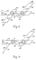
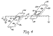
- FIGS. 3 and 4 are shown to illustrate arrangements wherein both balanced and single ended circuits can be used.
- FIGs 1, 2 and 5 wherein like reference numbers have been used for designating for like or similar elements, such reference numerals are also used for Figures 3 and 4.
- a balanced circuit is used with the main utility line 18, as in Figure 2
- a balance circuit is used for a lateral line 20, as in Figure 2
- a single ended circuit is used for lateral utility line 36.
- a single ended circuit is used with the main utility line 18 as in Figure 1
- balanced circuits for lateral line 20 and 36 are used, as in Figure 2.
- a passive marker 16 is supplied for use at each of the points where the lateral utility lines 20 and 36 connect with the main utility line 18 and are positioned for inductive coupling with the conductors associated with the main and lateral lines as heretofore described.
- the passive markers 16 can be used for locating other buried structures along a main utility line, a passive marker having a unique resonant frequency for a particular location or for each different type of location or structure can be used. For example, a resonant frequency of 100 KHz might be used for locating the connection of lateral lines to the main lines and 120 KHz for load coils, if the utility line is a telephone cable. Similarly, a different frequency could be used for each lateral connection to a main line.
- the marking tape will serve as a convenient way for placing the conductors under ground and will serve to warn an excavator of the presence of a utility line before an excavation effort reaches the level at which the utility line is buried.
- the two conductors carried by the marking tape are also usable to monitor the condition of the conductors to detect a break that may occur, since as by an excavation conducted along the utility line.
- the invention has been described in connection with location of buried conductors, it should be appreciated that the invention is broader in scope in that it is applicable also for locating any conductors as described which cannot be visibly traced.
- the first conductor of a system and the plurality of conductors that extend from the first conductor without ohmic contact being made to the first conductor may be located in the walls and/or floors of a building and serve as tracing wires for certain structures or elements located within the walls and/or floors of a building.
Landscapes
- Life Sciences & Earth Sciences (AREA)
- Physics & Mathematics (AREA)
- General Life Sciences & Earth Sciences (AREA)
- General Physics & Mathematics (AREA)
- Geophysics (AREA)
- Remote Sensing (AREA)
- Engineering & Computer Science (AREA)
- Environmental & Geological Engineering (AREA)
- Geology (AREA)
- Electromagnetism (AREA)
- Geophysics And Detection Of Objects (AREA)
- Radar Systems Or Details Thereof (AREA)
- Train Traffic Observation, Control, And Security (AREA)
- Communication Cables (AREA)
- Filters And Equalizers (AREA)
- Measurement Of Length, Angles, Or The Like Using Electric Or Magnetic Means (AREA)
- Remote Monitoring And Control Of Power-Distribution Networks (AREA)
Claims (6)
- Procédé pour déterminer l'endroit caché de l'un quelconque parmi un premier conducteur électrique isolé (10) et plusieurs conducteurs électriques isolés (24, 38), chacun de ceux-ci s'étendant depuis le premier conducteur (10) suivant un certain angle et comportant une partie voisine du premier conducteur (10) mais sans contact ohmique avec ce premier conducteur (10), en prévoyant plusieurs éléments de marquage passifs (16) comportant chacun une bobine et un condensateur agencés pour former un circuit résonant, en utilisant une source (14) de signaux alternatifs et en utilisant un récepteur (22) capable de recevoir un signal à la fréquence des signaux fournis par cette source de signaux (14) et communiquant à un opérateur l'intensité du signal reçu, caractérisé en ce qu'il comprend : la mise en place de la série des éléments de marquage passifs de manière que chacun des divers conducteurs électriques (24, 38) et le premier conducteur électrique (10) soient couplés par induction par l'intermédiaire d'un élément différent parmi les divers éléments de marquage passifs (16) ; l'établissement du premier conducteur (10) en tant que partie d'un circuit en boucle fermée ; l'établissement d'une pluralité de circuits en boucle fermée, comprenant chacun un conducteur différent parmi la série des conducteurs (24, 38) ; l'application de signaux alternatifs provenant de la source susdite de signaux à un premier des circuits susdits à boucle fermée, de manière que ces signaux soient transmis par induction depuis le premier cicuit susdit à boucle fermée aux circuits à boucle fermée restants suivant la fréquence de ces signaux alternatifs et le fréquence de résonance de chacun de ces circuits résonants ; et le déplacement du récepteur (22) latéralement à l'un quelconque de ces circuits à boucle fermée transportant ces signaux alternatifs et recevant des signaux électromagnétiques produits lorsqu'un tel circuit à boucle fermée transporte les signaux alternatifs susdits, pour établir la localisation de ces circuits à boucle fermée.
- Procédé suivant la revendication 1, dans lequel la source de signaux (14) est connectée physiquement au premier susdit des circuits à boucle fermée, pour alimenter les signaux alternatifs précités venant de la source de signaux à ce premier des circuits à boucle fermée.
- Procédé suivant la revendication 1, dans lequel la source de signaux (14) est couplée par induction au premier susdit des circuits à boucle fermée, pour appliquer les signaux alternatifs précités venant de la source de signaux au premier susdit des circuits à boucle fermée.
- Procédé suivant la revendication 1, dans lequel les circuits susdits à boucle fermée peuvent être des circuits équilibrés ou des circuits dont une extrémité est mise à la masse.
- Système permettant de déterminer l'endroit caché de l'un quelconque parmi un premier conducteur électrique isolé (10) et plusieurs conducteurs électriques isolés (24, 38), chacun de ceux-ci s'étendant depuis le premier conducteur (10) suivant un certain angle et comportant une partie qui est voisine de ce premier conducteur, aucun de ces divers conducteurs électriques (24, 38) n'étant en contact ohmique avec le premier conducteur (10), le système comprenant une série d'éléments de marquage passifs (16) comportant chacun une bobine et un condensateur agencés pour former un circuit résonant, caractérisé par : la série des éléments de marquage passifs (16) sont mis en place de manière que chacun des divers conducteurs électriques (24, 38) et le premier conducteur électrique (10) soient couplés par induction par l'intermédiaire d'un élément différent parmi les divers éléments de marquage passifs (16) ; la formation d'un circuit à boucle fermée en utilisant le premier conducteur susdit (10) en tant que partie de ce circuit ; et une série de circuits à boucle fermée, formés chacun au départ d'un conducteur différent parmi la série des conducteurs (24, 38), de sorte que des signaux alternatifs appliqués à un premier de ces circuits à boucle fermée sont transmis par induction depuis ce premier parmi ces circuits à boucle fermée vers les circuits à boucle fermée restants suivant la fréquence de ces signaux alternatifs et la fréquence de résonance de chacun des circuits résonants, pour assurer la production d'un signal électromagnétique décelable pour l'identification de la localisation du premier conducteur, et de l'un quelconque des divers conducteurs ou des éléments de marquage passifs susdits lors du transfert des signaux alternatifs.
- Système suivant la revendication 5, dans lequel les circuits susdits à boucle fermée peuvent être des circuits équilibrés ou des circuits comportant une extrémité mise à la terre.
Priority Applications (1)
| Application Number | Priority Date | Filing Date | Title |
|---|---|---|---|
| AT89304710T ATE88578T1 (de) | 1988-05-11 | 1989-05-10 | Anordnung und verfahren mit passiven resonanzschaltungsmarken zur lokalisierung von eingegrabenen elektrischen leitungen. |
Applications Claiming Priority (2)
| Application Number | Priority Date | Filing Date | Title |
|---|---|---|---|
| US193250 | 1988-05-11 | ||
| US07/193,250 US4866388A (en) | 1988-05-11 | 1988-05-11 | System and method with passive resonant circuit markers for locating buried electrical conductors |
Publications (3)
| Publication Number | Publication Date |
|---|---|
| EP0341994A2 EP0341994A2 (fr) | 1989-11-15 |
| EP0341994A3 EP0341994A3 (en) | 1990-08-01 |
| EP0341994B1 true EP0341994B1 (fr) | 1993-04-21 |
Family
ID=22712835
Family Applications (1)
| Application Number | Title | Priority Date | Filing Date |
|---|---|---|---|
| EP89304710A Expired - Lifetime EP0341994B1 (fr) | 1988-05-11 | 1989-05-10 | Dispositif et procédé avec marqueurs à circuit de résonance passif pour localiser des conducteurs électriques enterrés |
Country Status (11)
| Country | Link |
|---|---|
| US (1) | US4866388A (fr) |
| EP (1) | EP0341994B1 (fr) |
| JP (1) | JP2858784B2 (fr) |
| KR (1) | KR970011114B1 (fr) |
| AT (1) | ATE88578T1 (fr) |
| AU (1) | AU600200B2 (fr) |
| BR (1) | BR8902161A (fr) |
| CA (1) | CA1317005C (fr) |
| DE (1) | DE68906073T2 (fr) |
| DK (1) | DK173268B1 (fr) |
| ES (1) | ES2039854T3 (fr) |
Families Citing this family (17)
| Publication number | Priority date | Publication date | Assignee | Title |
|---|---|---|---|---|
| US5430379A (en) * | 1993-08-27 | 1995-07-04 | Minnesota Mining And Manufacturing Company | Conductor locator adapter for electronic markers |
| GB9501162D0 (en) * | 1995-01-20 | 1995-03-08 | Radiodetection Ltd | Conductor identification |
| GB9508399D0 (en) * | 1995-04-25 | 1995-06-14 | Radiodetection Ltd | Location of underground objects |
| US6218840B1 (en) * | 1998-05-18 | 2001-04-17 | John Fridy Warren | Apparatus allowing continuous radio detection of underground utilities while maintaining cathodic isolation |
| US6388575B1 (en) | 1999-11-05 | 2002-05-14 | Industrial Technology, Inc. | Addressable underground marker |
| CA2311834C (fr) | 2000-06-16 | 2002-09-24 | Norscan Instruments Ltd. | Methode et appareil interactifs de reperage et d'identification des installations de service public |
| US7091872B1 (en) * | 2002-07-01 | 2006-08-15 | Metrotech Corporation | Controlled power source for underground line location |
| US20060068754A1 (en) * | 2004-09-30 | 2006-03-30 | Helena Goldfarb | System and method for securing a large infrastructure |
| GB0505089D0 (en) * | 2005-03-11 | 2005-04-20 | Glaxo Group Ltd | System and methods for detecting environmental conditions |
| US8351869B2 (en) * | 2005-09-22 | 2013-01-08 | Ideal Industries, Inc. | Electric circuit tracer |
| US7696879B2 (en) * | 2007-12-18 | 2010-04-13 | Alcatel Lucent | Ascertaining physical routing of cabling interconnects |
| US7901306B2 (en) * | 2008-03-14 | 2011-03-08 | Minarovic Joe T | Electronic marker stakes for sports fields |
| CN102749661B (zh) * | 2011-04-22 | 2016-11-09 | 郝彤 | 非开挖式后装管内电子标识的安装方法 |
| NL2014762B1 (en) * | 2015-05-04 | 2017-01-26 | Fugro Tech Bv | Sensor system. |
| EP3417320B1 (fr) * | 2016-02-16 | 2025-05-07 | SeeScan, Inc. | Dispositifs et systèmes de marquage d'équipements enterrés |
| JP7060254B2 (ja) * | 2016-09-08 | 2022-04-26 | イーエーエス,アイピー,エルエルシー | 信号テープ |
| US11035973B2 (en) * | 2017-12-20 | 2021-06-15 | Armada Technologies, LLC | Passive underground locator beacon |
Family Cites Families (5)
| Publication number | Priority date | Publication date | Assignee | Title |
|---|---|---|---|---|
| US2167490A (en) * | 1937-05-07 | 1939-07-25 | Henry B Burr | Apparatus for locating concealed conductive bodies |
| US2148389A (en) * | 1938-01-14 | 1939-02-21 | Joslyn Mfg & Supply Co | Signaling system and method |
| US4119908A (en) * | 1975-11-28 | 1978-10-10 | A. P. C. Industries, Inc. | Method for locating buried markers which are disposed along the path of an underground conductor |
| US4712094A (en) * | 1986-05-29 | 1987-12-08 | Minnesota Mining And Manufacturing Company | Self-orienting passive marker structure |
| US4767237A (en) * | 1986-08-26 | 1988-08-30 | Minnesota Mining And Manufacturing Company | Marking tape with wire conductors and methods for use |
-
1988
- 1988-05-11 US US07/193,250 patent/US4866388A/en not_active Expired - Lifetime
-
1989
- 1989-04-24 CA CA000597556A patent/CA1317005C/fr not_active Expired - Fee Related
- 1989-04-27 AU AU33802/89A patent/AU600200B2/en not_active Ceased
- 1989-05-08 KR KR1019890006103A patent/KR970011114B1/ko not_active Expired - Fee Related
- 1989-05-09 BR BR898902161A patent/BR8902161A/pt unknown
- 1989-05-09 DK DK198902275A patent/DK173268B1/da not_active IP Right Cessation
- 1989-05-10 AT AT89304710T patent/ATE88578T1/de not_active IP Right Cessation
- 1989-05-10 ES ES198989304710T patent/ES2039854T3/es not_active Expired - Lifetime
- 1989-05-10 EP EP89304710A patent/EP0341994B1/fr not_active Expired - Lifetime
- 1989-05-10 DE DE8989304710T patent/DE68906073T2/de not_active Expired - Fee Related
- 1989-05-10 JP JP1115267A patent/JP2858784B2/ja not_active Expired - Lifetime
Also Published As
| Publication number | Publication date |
|---|---|
| JP2858784B2 (ja) | 1999-02-17 |
| AU3380289A (en) | 1989-11-16 |
| EP0341994A3 (en) | 1990-08-01 |
| AU600200B2 (en) | 1990-08-02 |
| KR970011114B1 (ko) | 1997-07-07 |
| DE68906073T2 (de) | 1993-09-09 |
| KR890017550A (ko) | 1989-12-16 |
| EP0341994A2 (fr) | 1989-11-15 |
| JPH01321389A (ja) | 1989-12-27 |
| DK227589A (da) | 1989-11-12 |
| BR8902161A (pt) | 1990-01-02 |
| DE68906073D1 (de) | 1993-05-27 |
| ATE88578T1 (de) | 1993-05-15 |
| DK173268B1 (da) | 2000-05-29 |
| ES2039854T3 (es) | 1993-10-01 |
| CA1317005C (fr) | 1993-04-27 |
| DK227589D0 (da) | 1989-05-09 |
| US4866388A (en) | 1989-09-12 |
Similar Documents
| Publication | Publication Date | Title |
|---|---|---|
| EP0341994B1 (fr) | Dispositif et procédé avec marqueurs à circuit de résonance passif pour localiser des conducteurs électriques enterrés | |
| US4119908A (en) | Method for locating buried markers which are disposed along the path of an underground conductor | |
| US4767237A (en) | Marking tape with wire conductors and methods for use | |
| US11906685B2 (en) | Distinguishing false signals in cable locating | |
| US5714885A (en) | Method and apparatus for locating faluts in buried conductors | |
| EP0793812B1 (fr) | Procede et appareil de reperage des cables d'alimentation en courant electrique ou des tuyaux d'alimentation en eau courante | |
| WO1997012262A9 (fr) | Procede et appareil de reperage des cables ou tuyaux d'alimentation publique en courant electrique | |
| US3831086A (en) | Apparatus for identifying and tracing a pair of conductors | |
| US5995588A (en) | Tone location device for locating faults in a paired line | |
| CA1279112C (fr) | Ruban marqueur a fils conducteurs, et son mode d'emploi | |
| GB2300267A (en) | Location of underground objects | |
| JPS5810147Y2 (ja) | 移動体停止制御用信号検出装置 |
Legal Events
| Date | Code | Title | Description |
|---|---|---|---|
| PUAI | Public reference made under article 153(3) epc to a published international application that has entered the european phase |
Free format text: ORIGINAL CODE: 0009012 |
|
| AK | Designated contracting states |
Kind code of ref document: A2 Designated state(s): AT BE CH DE ES FR GB IT LI NL SE |
|
| PUAL | Search report despatched |
Free format text: ORIGINAL CODE: 0009013 |
|
| AK | Designated contracting states |
Kind code of ref document: A3 Designated state(s): AT BE CH DE ES FR GB IT LI NL SE |
|
| 17P | Request for examination filed |
Effective date: 19901113 |
|
| 17Q | First examination report despatched |
Effective date: 19910813 |
|
| GRAA | (expected) grant |
Free format text: ORIGINAL CODE: 0009210 |
|
| AK | Designated contracting states |
Kind code of ref document: B1 Designated state(s): AT BE CH DE ES FR GB IT LI NL SE |
|
| REF | Corresponds to: |
Ref document number: 88578 Country of ref document: AT Date of ref document: 19930515 Kind code of ref document: T |
|
| ITF | It: translation for a ep patent filed | ||
| REF | Corresponds to: |
Ref document number: 68906073 Country of ref document: DE Date of ref document: 19930527 |
|
| ET | Fr: translation filed | ||
| REG | Reference to a national code |
Ref country code: ES Ref legal event code: FG2A Ref document number: 2039854 Country of ref document: ES Kind code of ref document: T3 |
|
| PLBE | No opposition filed within time limit |
Free format text: ORIGINAL CODE: 0009261 |
|
| STAA | Information on the status of an ep patent application or granted ep patent |
Free format text: STATUS: NO OPPOSITION FILED WITHIN TIME LIMIT |
|
| 26N | No opposition filed | ||
| ITTA | It: last paid annual fee | ||
| EAL | Se: european patent in force in sweden |
Ref document number: 89304710.0 |
|
| PGFP | Annual fee paid to national office [announced via postgrant information from national office to epo] |
Ref country code: FR Payment date: 20010418 Year of fee payment: 13 |
|
| PGFP | Annual fee paid to national office [announced via postgrant information from national office to epo] |
Ref country code: NL Payment date: 20010419 Year of fee payment: 13 Ref country code: DE Payment date: 20010419 Year of fee payment: 13 |
|
| PGFP | Annual fee paid to national office [announced via postgrant information from national office to epo] |
Ref country code: SE Payment date: 20010420 Year of fee payment: 13 Ref country code: GB Payment date: 20010420 Year of fee payment: 13 Ref country code: CH Payment date: 20010420 Year of fee payment: 13 Ref country code: AT Payment date: 20010420 Year of fee payment: 13 |
|
| PGFP | Annual fee paid to national office [announced via postgrant information from national office to epo] |
Ref country code: BE Payment date: 20010511 Year of fee payment: 13 |
|
| PGFP | Annual fee paid to national office [announced via postgrant information from national office to epo] |
Ref country code: ES Payment date: 20010608 Year of fee payment: 13 |
|
| REG | Reference to a national code |
Ref country code: GB Ref legal event code: IF02 |
|
| PG25 | Lapsed in a contracting state [announced via postgrant information from national office to epo] |
Ref country code: GB Free format text: LAPSE BECAUSE OF NON-PAYMENT OF DUE FEES Effective date: 20020510 Ref country code: AT Free format text: LAPSE BECAUSE OF NON-PAYMENT OF DUE FEES Effective date: 20020510 |
|
| PG25 | Lapsed in a contracting state [announced via postgrant information from national office to epo] |
Ref country code: SE Free format text: LAPSE BECAUSE OF NON-PAYMENT OF DUE FEES Effective date: 20020511 Ref country code: ES Free format text: LAPSE BECAUSE OF NON-PAYMENT OF DUE FEES Effective date: 20020511 |
|
| PG25 | Lapsed in a contracting state [announced via postgrant information from national office to epo] |
Ref country code: LI Free format text: LAPSE BECAUSE OF NON-PAYMENT OF DUE FEES Effective date: 20020531 Ref country code: CH Free format text: LAPSE BECAUSE OF NON-PAYMENT OF DUE FEES Effective date: 20020531 Ref country code: BE Free format text: LAPSE BECAUSE OF NON-PAYMENT OF DUE FEES Effective date: 20020531 |
|
| PG25 | Lapsed in a contracting state [announced via postgrant information from national office to epo] |
Ref country code: NL Free format text: LAPSE BECAUSE OF NON-PAYMENT OF DUE FEES Effective date: 20021201 |
|
| PG25 | Lapsed in a contracting state [announced via postgrant information from national office to epo] |
Ref country code: DE Free format text: LAPSE BECAUSE OF NON-PAYMENT OF DUE FEES Effective date: 20021203 |
|
| GBPC | Gb: european patent ceased through non-payment of renewal fee |
Effective date: 20020510 |
|
| EUG | Se: european patent has lapsed | ||
| REG | Reference to a national code |
Ref country code: CH Ref legal event code: PL |
|
| PG25 | Lapsed in a contracting state [announced via postgrant information from national office to epo] |
Ref country code: FR Free format text: LAPSE BECAUSE OF NON-PAYMENT OF DUE FEES Effective date: 20030131 |
|
| NLV4 | Nl: lapsed or anulled due to non-payment of the annual fee |
Effective date: 20021201 |
|
| REG | Reference to a national code |
Ref country code: FR Ref legal event code: ST |
|
| REG | Reference to a national code |
Ref country code: ES Ref legal event code: FD2A Effective date: 20030611 |
|
| PG25 | Lapsed in a contracting state [announced via postgrant information from national office to epo] |
Ref country code: IT Free format text: LAPSE BECAUSE OF NON-PAYMENT OF DUE FEES;WARNING: LAPSES OF ITALIAN PATENTS WITH EFFECTIVE DATE BEFORE 2007 MAY HAVE OCCURRED AT ANY TIME BEFORE 2007. THE CORRECT EFFECTIVE DATE MAY BE DIFFERENT FROM THE ONE RECORDED. Effective date: 20050510 |