EP0342031A2 - Système d'interrupteur rotatif à pousser-tirer d'un phare d'automobile - Google Patents
Système d'interrupteur rotatif à pousser-tirer d'un phare d'automobile Download PDFInfo
- Publication number
- EP0342031A2 EP0342031A2 EP89304774A EP89304774A EP0342031A2 EP 0342031 A2 EP0342031 A2 EP 0342031A2 EP 89304774 A EP89304774 A EP 89304774A EP 89304774 A EP89304774 A EP 89304774A EP 0342031 A2 EP0342031 A2 EP 0342031A2
- Authority
- EP
- European Patent Office
- Prior art keywords
- switch
- rheostat
- rotatable
- panel
- detent
- Prior art date
- Legal status (The legal status is an assumption and is not a legal conclusion. Google has not performed a legal analysis and makes no representation as to the accuracy of the status listed.)
- Granted
Links
Images




Classifications
-
- H—ELECTRICITY
- H01—ELECTRIC ELEMENTS
- H01H—ELECTRIC SWITCHES; RELAYS; SELECTORS; EMERGENCY PROTECTIVE DEVICES
- H01H25/00—Switches with compound movement of handle or other operating part
- H01H25/06—Operating part movable both angularly and rectilinearly, the rectilinear movement being along the axis of angular movement
Definitions
- the present invention relates to automotive electrical switches and more particularly to a combined push-pull and rotary switch specifically designed for turning a headlight “off” and “on” in a push-pull manner in a vehicle, as well as for controlling a number of other electrical functions by rotating the push-pull control knob, including not only, as is standard, the brightness of the panel lights, but also for example, an "off" switch for the vehicle's "dome” light.
- a headlight switch for turning the parking and headlights “on” and “off” by means of a longitudinal pulling or pushing action, respectively, which switch is also combined with a rheostat for dimming or brightening the panel lights on the dashboard by a circular, twisting or rotary motion, to a final clockwise position completely turning them off.
- this switching structure more recently has been used as well to turn another light “on” and “off,” such as, for example, the interior dome light.
- the function of the dome light switch is to, for example, turn off the dome light circuit, when one or more of the vehicle's doors or tailgate is open during day light hours, by rotating the shaft of the overall switch to the extreme clockwise position (as viewed from the front).
- the supplemental "on"/"off" switch for the dome light was mounted on the side, exterior of the otherwise in-line construction, with the prior art switch having an exposed arm extending generally longitudinally and parallel to the center axis of the switch with its front end bent inwardly to position its distal tip adjacent to the side of the rheostat, so that a projection on the rheostat would cause the switch arm to be moved, breaking the normal electrical contact within the switch.
- the switch arm required ultrasonic welding between it and its associated terminal, a relatively difficult process.
- the present invention in its preferred embodiment is designed to replace the previous outboard, dome light switch and to further include another electrical function, namely, for example, a fluorescent panel light switch, with an in-line, highly compact and reliable, relatively inexpensive, rotatable, multi-function switching structure of preferably multi-spaced-panel construction, all of which is positioned and located centrally in-line in the front bracket area previously occupied by a ceramic rheostat and a spacer at the front area of the composite switch structure, with none of the switches located outboard of the main body of the in-line composite switch.
- another electrical function namely, for example, a fluorescent panel light switch
- the present invention in its supplemental switching structures, does not add at all to the overall exterior bulk of the basic, composite rotary & push-pull basic switch structure.
- the switching structures are actuated by the rotation of the shaft upon which the other rotary parts of the composite switch are mounted, providing it with a direct drive, avoiding any dependency on, for example, mechanically interfacing an elongated exposed arm on the switch with a physical protrusion on the rheostat's surface.
- the present invention in its preferred embodiment, not only provides the "on"/"off" switch function for a vehicle light, such as for example the dome light, but also provides in the same central, frontal area a switching circuit for another electrical function, particularly, for example, a supplemental fluorescent panel lighting system.
- the preferred, exemplary embodiment achieves all of this by utilizing two, spaced, parallel, facing panels having three, spaced, parallel, flat, laterally extended, operative planar surfaces - - a first, front panel having on its rearwardly facing side a rheostat planar surface including a series of circularly disposed, peripherally spaced, resistive layers, which, in conjunction with a rotatable rheostat contactor arm, serve the rheostat dimming function for the panel lights; - a second, rear panel, having on its side facing the first panel, - a detent planar surface including a series of raised protrusions (for example, three), which serve as detent positions in cooperation with a scrubbing, flexible, rotatable arm sweeping across it, as the central control knob and shaft are rotated, along with an axially extended and movable, protruding plunger, which also extends to the other side of the panel to coact with the switch contactors for, for example, a "
- a common hub In conjunction with the two spaced panels, there is included between the two panels on a common hub the rheostat contactor arm scrubbing against the rheostat planar surface and the detent and plunger actuator arm scrubbing against the opposed, detent plane; while on the other side of the second panel there is included a rotatable dome & fluorescent contactor structure scrubbing against the switch circuit plane.
- the latter contactor structure is rotated conjunctively with but electrically isolated from the rheostat contactor arm, and the detent and plunger actuator arm does not need to conduct any electricity.
- the three planar surfaces are to some degree relatively reversible, that is, for example, the detent planar surface and the switch circuit planar surface could be reversed or, for further example, the rheostat planar surface could be switched with the detent planar surface, with the rheostat arm appropriately re-configured to also cooperate with and actuate the "dome" switch plunger.
- the detent protrusions could be provided on either the rheostat or the switch circuit surfaces, with the actuator arm being combined with the rheostat arm or the rotatable switching structure.
- both of the rotatable arms and the rotatable switching structure could be combined together to sweep across the same panel side, with all of the detent protrusions, circuit pads and contacts and all of the rheostat resistive layers appropriately laid out on it, with the contact portions for each of the rotatable members using different radii of revolution in order not to interfere with one another.
- the present invention provides, in conjunction with the push-pull headlight switch, a highly compact, functionally increased, multi-function, rotary switching structure controlling, for example, the brightness of the panel light, a "dome” main and a “dome” bypass circuit and a supplemental fluorescent circuit, all in the same space previously occupied by the ceramic rheostat and a spacer in the rotary, push-pull headlight switch of the prior art, all with no switches hanging off of the side of the main body of the rotary switch body.
- the ceramic rheostat and the "out board" dome switch of the prior art are illustrated as elements 3 & 6, respectively, in Figures 1A & 1B of US-4827241 referred to above, while the prior art spacer is illustrated as element 5 in Figures 2A & 2B thereof.
- Figures1, 2 & 3 are front, top and side views, respectively, of the overall headlight switch with buzzer circuit assembly, including the preferred embodiment of the rotary, in-line, multi-spaced-panel switching structure for the panel light brightness, the electrical dome light switch and the fluorescent light switch, all located in the front, central bracket portion of the basic composite switch body; while
- the overall, composite headlight switch 1 (with buzzer circuit) includes two basic components, the main electrical switching component 2 and the front bracket 3 defining a front bracket area 4 .
- These components can be and preferably are identical to those used in the prior art.
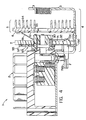
- the internal structure and the terminal pin layout for the prior art switching component 2 can be seen in Figures 4 & 2 , respectively.
- the rheostat 5 Within the front bracket area 4 are included the rheostat 5 and the switch components for the "dome" light bypass circuit and the supplemental fluorescent panel light, as explained more fully below, all contained on or affiliated with two, parallel, spaced panels 6 & 7 .
- the front bracket area 4 typically has a longitudinal dimension of about 1.25 inches (32mm) in its depth, while the panels 6 & 7 can have exemplary thicknesses of, for example, of the order of 0.03 inch (0.8mm) and 0.125 inch (3.2mm), respectively, with the entire novel switch components made up of the panels 6 & 7 and their attendant central components, including the heat sink 64 , having a combined exemplary thickness or depth of about 1 inch (25mm), still leaving a significant amount of space in front of the heat sink 64 , as can best be seen in Figures 2 & 4 .
- the dome "on"/"off" switch is located within the front area 4 , and, in this same area, is also located the switch for the supplemental fluorescent light circuit, all as explained more fully below.
- Each of these switches, as well as the rheostat 5 are actuated and controlled through the rotation of the central control shaft 8 as part of the rotary switch structure.
- the two, parallel, spaced, facing panels 6 & 7 which are substantially flat over most of their main sides, include three, laterally extended, operative planar surfaces, all located within the front bracket area 4 .
- the front panel 6 made primarily of electrically insulating material, has on its back side 61 a rheostat planar surface (shown in plan view in Fig. 5 ), including a series of circularly disposed, peripherally spaced, resistive layers 62 , which, in conjunction with a rotatable rheostat contactor arm 91 , provide the rheostat dimming function for the panel lights, as the rotary shaft 8 is rotated in a clockwise direction.
- a rheostat planar surface shown in plan view in Fig. 5
- a series of circularly disposed, peripherally spaced, resistive layers 62 which, in conjunction with a rotatable rheostat contactor arm 91 , provide the rheostat dimming function for the panel lights, as the rotary shaft 8 is rotated in a clockwise direction.
- no resistance layer 63 is included at the top side of the panel 6 which provides a “full bright” initial contact area for the rheostat arm 91 , with the associated contact surface member 63A being connected to the " I " terminal.
- the initial resistive layer 62S providing an initial minimum resistance and dimming
- additional resistance is added into the main panel light circuit by subsequent resistive layers 62, causing the main panel lights to further dim.
- the rheostat arm 91 passes the last, maximum resistance, "full dim" layer 62F , it then rests on the electrically insulating surface of the main body of the panel 6 , effectively cutting off the main panel lights.
- a laterally extended heat sink 64 is attached to the front side 65 of the panel 6 to dissipate the heat generated by the resistive layers 62 during the main panel light dimming function.
- the ceramic rotatable rheostat body (note element 5 of US-4827241) could be used if desired.
- the rear panel 7 has on its front side 71 facing the first panel 6, a generally flat, detent planar surface having, for example, three raised, circular protrusions or bosses 72A , 72B & 72C (note Figure 6 ), which serve as detent positions in cooperation with a flexible, rotatable detent arm 92 sweeping across them and the front side 71 , as the control knob rod 8 is rotated.
- the initial detent protrusion 72A (the lower side of which represents the starting position) serves to indicate or bracket the position of the "dome” light being “on,” at which point the "dome” circuit is closed, while detent protrusion 72B with the protrusion 72A brackets the positions for the supplemental fluorescent circuit actuation being "on.”
- the final detent protrusion 72C indicates the entrance position of the "dome” light bypass cut off, which causes the "dome” circuit to be bypassed even if a vehicle door is open, as well as the main panel light “off” position.
- the second panel 7 also includes an axially extended and movable plunger 73 (note also Figure 6A ), which normally protrudes out past the front side 71 , but also extends to the other, rear side 74 of the panel 7 to coact with relatively movable, switch contactors 75A & 75B for the "dome" light override circuit.
- the distal, associated ends 75C & 75D of the relatively movable contactors 75A & 75B respectively, extend out from the sides of the front bracket area 4 defined by the bracket 3 for connection into the sup plemental connector housing 11 for connection into the inline dome terminals of the electrical circuitry of the vehicle.
- the rear side 74 of the rear panel 7 which is primarily made of an electrically insulating material with various conductive pads of, for example, copper plate added, includes a switch circuit planar surface forming the "dome” and fluorescent circuit board.
- the circuit elements include the spaced, conductive surfaces 76 & 77 , which control the main "dome” light circuit and the supplemental fluorescent panel light circuit in conjunction with the "dome” and fluorescent contactor arms, as well as the movable, conductive contacts 75A & 75B , which control the "dome” light bypass circuit in conjunction with the movement of the plunger 73 .
- the conductive surface 76 forms a dome circuit pad, which is in electrical contact with the " D " terminal through connector 76A , while the conductive surface 77 forms a fluorescent circuit pad electrically connected to the " F " terminal by the internal conductive pad 78A .
- a resistor 78 e.g. one K ohm, quarter watt
- a "ground” conductive pad 79 extends from around the central hub area 79A to the lower edge of the board panel 7 and is in electrical connection with the standard "ground” terminal 79B (note Fig. 4 ).
- a supplemental, longitudinally extended, " U " shaped, conductive holder 79C grounds the conductive pad 79 to the bracket 3 and the ground terminal 79B .
- the holder 79C which is affixed to the bracket 3 by, for example, rivets, also has side, female slots 79D in it, into which laterally extending, side, male tabs 6A & 7A on the panels 6 & 7 , respectively are inserted (note particularly Figs.
- a common hub 90 of electrically insulating material the radially extending, rheostat contactor arm 91 scrubbing against the rheostat planar surface 61 and the radially extending, detent and plunger actuator arm 92 scrubbing against the opposed detent planar surface 71 .
- the rotatable arms 91 & 92 are both flexible and bear against their respective operative surfaces with a flexible force in opposite longitudinal directions.
- the actuator arm 92 does not serve to conduct electricity and can be made either of conductive or non-conductive material. Its function is primarily mechanical, serving as a detent "clicker" in conjunction with the buss protrusions 72A-C , and to mechanically break or open the circuit formed between the contacts 75A & 75B .
- a rotatable dome & fluorescent contactor structure 93 scrubbing against the switch circuit planar surface 74 .
- the latter contactor structure 93 which integrally includes the dome and fluorescent contactor arms 94 & 95 , respectively, and the central contactor hub 93A , is rotated conjunctively with but electrically isolated from the rheostat contactor arm 91 and the detent and plunger actuator arm 92 .
- the central contactor hub 93A which can have one or more contacting dimples on its underside, always remains in grounding, electrical contact with the central grounding hub plate portion 79A .
- the actuator arm 92 is positioned between the detent protrusions 72A & 72B , at which position the dimpled, distal end of the dome contactor arm 94 is no longer in contact with the dome pad 76 , opening its associated circuit, while the fluorescent contactor arm 95 still remains in contact with the fluorescent pad 77 , maintaining its associated circuit closed.
- the rotatable arms 91 & 92 with the hub 90 , the rotatable switching structure 93 and the two panels 6 & 7 are all located within the front bracket area 4 of the main, overall switch body 1 .
- Exemplary insulating materials for the front panel 6 is a ceramic and for the back panel 7 a polymer.
- the three operative surfaces could be switched around or even partially or fully combined, as may be desired for enhanced compactness.
Landscapes
- Rotary Switch, Piano Key Switch, And Lever Switch (AREA)
- Switches With Compound Operations (AREA)
- Lighting Device Outwards From Vehicle And Optical Signal (AREA)
Applications Claiming Priority (2)
| Application Number | Priority Date | Filing Date | Title |
|---|---|---|---|
| US193017 | 1988-05-12 | ||
| US07/193,017 US4885434A (en) | 1988-05-12 | 1988-05-12 | Automotive headlight, push-pull, rotary switch system |
Publications (3)
| Publication Number | Publication Date |
|---|---|
| EP0342031A2 true EP0342031A2 (fr) | 1989-11-15 |
| EP0342031A3 EP0342031A3 (fr) | 1991-05-29 |
| EP0342031B1 EP0342031B1 (fr) | 1994-08-10 |
Family
ID=22711954
Family Applications (1)
| Application Number | Title | Priority Date | Filing Date |
|---|---|---|---|
| EP89304774A Expired - Lifetime EP0342031B1 (fr) | 1988-05-12 | 1989-05-11 | Système d'interrupteur rotatif à pousser-tirer d'un phare d'automobile |
Country Status (4)
| Country | Link |
|---|---|
| US (1) | US4885434A (fr) |
| EP (1) | EP0342031B1 (fr) |
| DE (1) | DE68917364T2 (fr) |
| ES (1) | ES2061988T3 (fr) |
Cited By (4)
| Publication number | Priority date | Publication date | Assignee | Title |
|---|---|---|---|---|
| EP0626705A3 (fr) * | 1993-05-28 | 1995-01-18 | Eaton Corp | Commutateur combiné rotatif et à bouton-poussoir. |
| EP1630038A3 (fr) * | 2004-08-26 | 2006-10-18 | TRW Automotive Electronics & Components GmbH & Co. KG | Interrupteur rotatif d'éclairage pour véhicules |
| DE10320988B4 (de) * | 2002-10-31 | 2008-05-29 | Lear Corp., Southfield | Schaltungsarchitektur für einen Fahrzeugscheinwerferschalter |
| US7485985B2 (en) | 2001-10-15 | 2009-02-03 | Volvo Lastvagnar Ab | Rotary switch |
Families Citing this family (11)
| Publication number | Priority date | Publication date | Assignee | Title |
|---|---|---|---|---|
| US5140111A (en) * | 1990-11-27 | 1992-08-18 | United Technologies Automotive, Inc. | Cam actuated dome light bypass switch |
| US5264821A (en) * | 1990-11-27 | 1993-11-23 | United Technologies Automotive | Rotary, push-pull headlight switch with ceramic coated metal substrate rheostat and cam actuated dome light bypass switch |
| US5181313A (en) * | 1990-12-19 | 1993-01-26 | United Technologies Automotive | Method of making a variable power resistor |
| US5119063A (en) * | 1990-12-19 | 1992-06-02 | United Technologies Corporation | Variable power resistor |
| DE4319543A1 (de) * | 1993-06-12 | 1994-12-15 | Eaton Controls Gmbh | Kraftfahrzeug-Lichtschalter |
| US5546067A (en) * | 1994-12-14 | 1996-08-13 | United Technologies Automotive, Inc. | Rotary potentiometer assembly for a push-pull switch |
| US5708243A (en) * | 1996-12-16 | 1998-01-13 | United Technologies Automotive, Inc. | Multi-position, multi-directional electric switch mechanism |
| US6281453B1 (en) | 2000-03-03 | 2001-08-28 | Lear Corporation | Carrier and knob stop encoder assembly |
| US6794770B2 (en) * | 2001-04-26 | 2004-09-21 | Tutco, Inc. | Interface control switch |
| DE10239387B4 (de) * | 2002-03-01 | 2011-04-07 | Volkswagen Ag | Versenkbarer Schalter |
| US7514645B2 (en) * | 2005-05-31 | 2009-04-07 | Elc Industries Corp. | Master light switch for ground vehicles |
Family Cites Families (8)
| Publication number | Priority date | Publication date | Assignee | Title |
|---|---|---|---|---|
| US2942220A (en) * | 1956-11-13 | 1960-06-21 | Gen Motors Corp | Control device |
| DE2001555B2 (de) * | 1970-01-15 | 1971-11-04 | Schalteinrichtung fuer kraftfahrzeuge | |
| US3840838A (en) * | 1972-04-04 | 1974-10-08 | Matsushita Electric Industrial Co Ltd | Switch assembly including rotary variable resistor |
| US4081782A (en) * | 1976-08-04 | 1978-03-28 | Bourns, Inc. | Combined rotary potentiometer and switch |
| US4117444A (en) * | 1977-07-14 | 1978-09-26 | Bourns, Inc. | Hearing aid volume control |
| ES529109A0 (es) * | 1984-01-24 | 1984-10-01 | Piher Navarra Sa | Perfeccionamientos en los aparatos variadores de la resistencia y la conduccion de corriente de los circuitos electricos |
| DE3514708A1 (de) * | 1985-04-24 | 1986-10-30 | BSG-Schalttechnik GmbH & Co KG, 7460 Balingen | Drehpotentiometer mit schalter |
| US4827241A (en) * | 1987-10-30 | 1989-05-02 | United Technologies Automotive, Inc. | Combined, in-line spacer and switch, particularly for a vehicle's headlight |
-
1988
- 1988-05-12 US US07/193,017 patent/US4885434A/en not_active Expired - Fee Related
-
1989
- 1989-05-11 DE DE68917364T patent/DE68917364T2/de not_active Expired - Fee Related
- 1989-05-11 EP EP89304774A patent/EP0342031B1/fr not_active Expired - Lifetime
- 1989-05-11 ES ES89304774T patent/ES2061988T3/es not_active Expired - Lifetime
Cited By (5)
| Publication number | Priority date | Publication date | Assignee | Title |
|---|---|---|---|---|
| EP0626705A3 (fr) * | 1993-05-28 | 1995-01-18 | Eaton Corp | Commutateur combiné rotatif et à bouton-poussoir. |
| US7485985B2 (en) | 2001-10-15 | 2009-02-03 | Volvo Lastvagnar Ab | Rotary switch |
| DE10320988B4 (de) * | 2002-10-31 | 2008-05-29 | Lear Corp., Southfield | Schaltungsarchitektur für einen Fahrzeugscheinwerferschalter |
| EP1630038A3 (fr) * | 2004-08-26 | 2006-10-18 | TRW Automotive Electronics & Components GmbH & Co. KG | Interrupteur rotatif d'éclairage pour véhicules |
| US7342188B2 (en) | 2004-08-26 | 2008-03-11 | Trw Automotive Electronics & Components Gmbh & Co. Kg | Rotary light switch for motor vehicles |
Also Published As
| Publication number | Publication date |
|---|---|
| ES2061988T3 (es) | 1994-12-16 |
| EP0342031B1 (fr) | 1994-08-10 |
| DE68917364D1 (de) | 1994-09-15 |
| US4885434A (en) | 1989-12-05 |
| DE68917364T2 (de) | 1994-12-01 |
| EP0342031A3 (fr) | 1991-05-29 |
Similar Documents
| Publication | Publication Date | Title |
|---|---|---|
| EP0342031B1 (fr) | Système d'interrupteur rotatif à pousser-tirer d'un phare d'automobile | |
| CA1329413C (fr) | Interrupteur de telecommande de retroviseur electrique | |
| US5428513A (en) | Covered vanity mirror and flexible circuit | |
| JP3108011B2 (ja) | パワーウィンドの運動を制御するための装置 | |
| JPH09198968A (ja) | 自動車用複合スイッチレバー装置 | |
| US5546067A (en) | Rotary potentiometer assembly for a push-pull switch | |
| US5264821A (en) | Rotary, push-pull headlight switch with ceramic coated metal substrate rheostat and cam actuated dome light bypass switch | |
| US4827241A (en) | Combined, in-line spacer and switch, particularly for a vehicle's headlight | |
| US4609794A (en) | Printed circuit switch for windshield wiper motor | |
| CN1094848C (zh) | 杆式开关,特别是用于汽车中的转向柱开关 | |
| US5602427A (en) | Vehicle lighting switch | |
| US5140111A (en) | Cam actuated dome light bypass switch | |
| US20020112947A1 (en) | Switch structure with electrical device | |
| US6601905B1 (en) | Convertible power top and power window switch | |
| CN120418123A (zh) | 用于机动车的转向柱开关 | |
| GB2131939A (en) | Hand actuating apparatus for adjustment drives on automobiles | |
| GB1604432A (en) | Electrical switch combination | |
| JPH09120755A (ja) | 自動車に用いられるロータリ機構を備えた電気スイッチ、その動作方法及び該スイッチの組み立て方法 | |
| US4719323A (en) | Simplified vehicle lighting switch | |
| EP1551046B1 (fr) | Signal de reveil numérique, provenant d'une transformation par commutation de deux signaux analogiques | |
| EP1375260B1 (fr) | Commutateur véhiculaire | |
| US6515240B1 (en) | Compact headlamp/foglamp switch | |
| EP1739792B1 (fr) | Unité de circuit | |
| US3120588A (en) | Multiple purpose direction signaling apparatus | |
| US4398168A (en) | Switching mechanism |
Legal Events
| Date | Code | Title | Description |
|---|---|---|---|
| PUAI | Public reference made under article 153(3) epc to a published international application that has entered the european phase |
Free format text: ORIGINAL CODE: 0009012 |
|
| AK | Designated contracting states |
Kind code of ref document: A2 Designated state(s): DE ES FR GB IT SE |
|
| PUAL | Search report despatched |
Free format text: ORIGINAL CODE: 0009013 |
|
| AK | Designated contracting states |
Kind code of ref document: A3 Designated state(s): DE ES FR GB IT SE |
|
| 17P | Request for examination filed |
Effective date: 19911115 |
|
| 17Q | First examination report despatched |
Effective date: 19930923 |
|
| GRAA | (expected) grant |
Free format text: ORIGINAL CODE: 0009210 |
|
| AK | Designated contracting states |
Kind code of ref document: B1 Designated state(s): DE ES FR GB IT SE |
|
| ITF | It: translation for a ep patent filed | ||
| REF | Corresponds to: |
Ref document number: 68917364 Country of ref document: DE Date of ref document: 19940915 |
|
| ET | Fr: translation filed | ||
| REG | Reference to a national code |
Ref country code: ES Ref legal event code: FG2A Ref document number: 2061988 Country of ref document: ES Kind code of ref document: T3 |
|
| EAL | Se: european patent in force in sweden |
Ref document number: 89304774.6 |
|
| PGFP | Annual fee paid to national office [announced via postgrant information from national office to epo] |
Ref country code: FR Payment date: 19950410 Year of fee payment: 7 |
|
| PGFP | Annual fee paid to national office [announced via postgrant information from national office to epo] |
Ref country code: GB Payment date: 19950413 Year of fee payment: 7 |
|
| PGFP | Annual fee paid to national office [announced via postgrant information from national office to epo] |
Ref country code: SE Payment date: 19950418 Year of fee payment: 7 |
|
| PGFP | Annual fee paid to national office [announced via postgrant information from national office to epo] |
Ref country code: DE Payment date: 19950421 Year of fee payment: 7 |
|
| PGFP | Annual fee paid to national office [announced via postgrant information from national office to epo] |
Ref country code: ES Payment date: 19950505 Year of fee payment: 7 |
|
| PLBE | No opposition filed within time limit |
Free format text: ORIGINAL CODE: 0009261 |
|
| STAA | Information on the status of an ep patent application or granted ep patent |
Free format text: STATUS: NO OPPOSITION FILED WITHIN TIME LIMIT |
|
| 26N | No opposition filed | ||
| PG25 | Lapsed in a contracting state [announced via postgrant information from national office to epo] |
Ref country code: GB Effective date: 19960511 |
|
| PG25 | Lapsed in a contracting state [announced via postgrant information from national office to epo] |
Ref country code: SE Effective date: 19960512 |
|
| PG25 | Lapsed in a contracting state [announced via postgrant information from national office to epo] |
Ref country code: ES Free format text: LAPSE BECAUSE OF NON-PAYMENT OF DUE FEES Effective date: 19960513 |
|
| GBPC | Gb: european patent ceased through non-payment of renewal fee |
Effective date: 19960511 |
|
| PG25 | Lapsed in a contracting state [announced via postgrant information from national office to epo] |
Ref country code: FR Effective date: 19970131 |
|
| PG25 | Lapsed in a contracting state [announced via postgrant information from national office to epo] |
Ref country code: DE Effective date: 19970201 |
|
| EUG | Se: european patent has lapsed |
Ref document number: 89304774.6 |
|
| REG | Reference to a national code |
Ref country code: FR Ref legal event code: ST |
|
| REG | Reference to a national code |
Ref country code: ES Ref legal event code: FD2A Effective date: 19990503 |
|
| PG25 | Lapsed in a contracting state [announced via postgrant information from national office to epo] |
Ref country code: IT Free format text: LAPSE BECAUSE OF NON-PAYMENT OF DUE FEES;WARNING: LAPSES OF ITALIAN PATENTS WITH EFFECTIVE DATE BEFORE 2007 MAY HAVE OCCURRED AT ANY TIME BEFORE 2007. THE CORRECT EFFECTIVE DATE MAY BE DIFFERENT FROM THE ONE RECORDED. Effective date: 20050511 |