EP0342143A2 - Automatische Spannvorrichtung für ein in einer biegsamen Hülle geführtes Zugkabel - Google Patents
Automatische Spannvorrichtung für ein in einer biegsamen Hülle geführtes Zugkabel Download PDFInfo
- Publication number
- EP0342143A2 EP0342143A2 EP89500056A EP89500056A EP0342143A2 EP 0342143 A2 EP0342143 A2 EP 0342143A2 EP 89500056 A EP89500056 A EP 89500056A EP 89500056 A EP89500056 A EP 89500056A EP 0342143 A2 EP0342143 A2 EP 0342143A2
- Authority
- EP
- European Patent Office
- Prior art keywords
- support
- cable
- hollow cylindrical
- nut
- casing
- Prior art date
- Legal status (The legal status is an assumption and is not a legal conclusion. Google has not performed a legal analysis and makes no representation as to the accuracy of the status listed.)
- Granted
Links
Images


Classifications
-
- F—MECHANICAL ENGINEERING; LIGHTING; HEATING; WEAPONS; BLASTING
- F16—ENGINEERING ELEMENTS AND UNITS; GENERAL MEASURES FOR PRODUCING AND MAINTAINING EFFECTIVE FUNCTIONING OF MACHINES OR INSTALLATIONS; THERMAL INSULATION IN GENERAL
- F16C—SHAFTS; FLEXIBLE SHAFTS; ELEMENTS OR CRANKSHAFT MECHANISMS; ROTARY BODIES OTHER THAN GEARING ELEMENTS; BEARINGS
- F16C1/00—Flexible shafts; Mechanical means for transmitting movement in a flexible sheathing
- F16C1/10—Means for transmitting linear movement in a flexible sheathing, e.g. "Bowden-mechanisms"
- F16C1/22—Adjusting; Compensating length
- F16C1/226—Adjusting; Compensating length by adjusting the effective length of the sheathing
Definitions
- a turnbuckle is used with its corresponding lock nut which regulates the tension of the whole, or a compensation or take-up system by means of two cylindrical springs that act on the guides of the opposite ends of the flexible conductor.
- the aim of the patent is to prevent these problems of traditional arrangements, by managing to compensate for any lengthening taht might be produced and ensuring that the cable remains constantly tense at all times.
- the basic aim of the patent is to obtain an extremely simple device to fulfil the proposed aims.
- the device in question is made up of three small parts made of thermoplastic material, obtained by injection, and a helicoidal spring.
- One of these parts is a cylindrical casing, hollow on the inside, through which the cable is passed, with this cylindrical casing having a series of circumferentially equidistant grooves cut on its outside and by way of a thread with an angular profile and pitch determined depending on what is of interest. These grooves will occupy a certain length, which will be determined in terms of the total stretching that has to be considered througout the working life of the appliance.
- the ends of the said casing are each provided with cylindrical prolongations.
- One of these prolongations acts as a guide on the support casing and the other receives the cable conductor.
- the support-casing can form an integral part of the member that receives the automatic tension regulator of a simple support bushing on the corresponding support, as will be explained later in connection with the drawings.
- the end of the hollow cylindrical casing through which the cable conductor is lodged is connected to a support by a kind of clip by means of tongues of the said support, so that once that it has been inserted, it cannot be extracted.
- a helicoidal spring acts between the nut-like casing and this support, maintaining the tension at all times between both parts, so that when the cable lengthens, due to its own distension (slackening) or because of wear on the items on which it acts or is conducted, the nut-like casing slides over the hollow cylindrical casing, and given that the latter cannot move back in the opposite direction, as mentioned earlier, its tension or adjustment, which is that of the spring, is maintained at all times.
- the characteristics of this spring will be calculated to provide the tension required within a maximum and a minimum, within the field of operation reserved for the spring.
- the helicoidal spring is made to slide towards the bottom of a throat in the nut-like casing and then compressed, by pushing it with the support until it clips into the hollow cylindrical casing.
- the tension of the spring separates the said support and the nut-like casing, with which all the system becomes adjusted to the tension given by the spring.
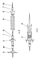
- a cable with its conductor (7) towards the right, and the whole of the patent towards the left.
- the latter is made up of the cylindrical casing (1), hollow on its inside, which has a series of grooves (2) cut on its outside like a screw thread, which partly occupy the length of the casing (1), from position (A) to position (B).
- the ends outside (A) and (B) are straight cylindrical sections, in one of which the support-casing (5) is housed, while the cable conductor (7) enters into the other.
- a part (3) like a nut is fitted.
- the inside of this part (3) is provided with grooves with an opposite profile to those of the casing (1), with dentated parts of special geometry, which make it possible for the casing (1) to be moved towards the right, as shown by (F), but do not allow any movement in the opposite direction.
- This support (5) can be an integral part of the member that receives the automatic tension regulator, or a simple support bushing on the corresponding support, as shown in figures 3 and 4.
- the other end of the casing (1) is clipped to the support (6) by means of the tongues (8) (figs. 1 and 3), in such a way that suitable fastening is achieved so that the support (6) cannot be taken outside.
- the assembly of the device can be deduced from figs. 3 and 4, with the cable (10) passing through the following parts, the support (5) and the casing (1) with the nut (3) over it.
- the cable (10) is clamped in the same way by the conductor (7), which in its turn receives the spring (9) and the support (6).
- the nut-like casing (3) is previously placed over the casing (1), with penetration being carried out from end (N), so that a channel of the casing (1) is left free on the said side (N), for the support (6) to be placed later.
- the assembly (1) - (3) is made to penetrate, through end (M), into the support (5), and at the same time the left end of the conductor (7) over (1), (fig. 4), which fastens the cable at the ends of the device, although without any tension.
- the spring (9) is inserted into the throat of the nut-like casing (3) and then compressed (fig. 4) with the support (6) until this support (6) becomes clipped, by the channel in end (N), over the casing (1). Finally, and on releasing pressure on the support (6), the tension of the spring (9) itself separates (3) and (6), with which the system becomes adjusted to the specific tension of the spring.
Landscapes
- Engineering & Computer Science (AREA)
- General Engineering & Computer Science (AREA)
- Health & Medical Sciences (AREA)
- Oral & Maxillofacial Surgery (AREA)
- Mechanical Engineering (AREA)
- Flexible Shafts (AREA)
Applications Claiming Priority (2)
| Application Number | Priority Date | Filing Date | Title |
|---|---|---|---|
| ES8801432 | 1988-05-09 | ||
| ES8801432A ES2011084A6 (es) | 1988-05-09 | 1988-05-09 | Regulador de tension automatico para cables de traccion guiados por conductos flexibles. |
Publications (3)
| Publication Number | Publication Date |
|---|---|
| EP0342143A2 true EP0342143A2 (de) | 1989-11-15 |
| EP0342143A3 EP0342143A3 (de) | 1991-09-25 |
| EP0342143B1 EP0342143B1 (de) | 1994-08-31 |
Family
ID=8256228
Family Applications (1)
| Application Number | Title | Priority Date | Filing Date |
|---|---|---|---|
| EP19890500056 Expired - Lifetime EP0342143B1 (de) | 1988-05-09 | 1989-05-08 | Automatische Spannvorrichtung für ein in einer biegsamen Hülle geführtes Zugkabel |
Country Status (3)
| Country | Link |
|---|---|
| EP (1) | EP0342143B1 (de) |
| DE (1) | DE68917780T2 (de) |
| ES (2) | ES2011084A6 (de) |
Cited By (6)
| Publication number | Priority date | Publication date | Assignee | Title |
|---|---|---|---|---|
| WO1993022571A1 (de) * | 1992-05-07 | 1993-11-11 | Küster & Co. Gmbh | Vorrichtung zur längenkorrektur von mechanisch-flexiblen fernbetätigungen |
| US5261292A (en) * | 1990-05-07 | 1993-11-16 | Pujol Y Tarrago S.A. | Self-adjustment device for adusting the length of control cables |
| ES2053387A2 (es) * | 1992-04-23 | 1994-07-16 | Dispositivos Acces Puertas Sa | Tensor para cables de traccion guiados por conductores flexibles. |
| ES2117512A1 (es) * | 1991-04-26 | 1998-08-01 | Castellon Melchor Daumal | Mejoras en el objeto de la patente principal, n-9101056 relativa a dispositivo para la regulacion automatica de la longitud del cable en mecanismos de mando a distancia. |
| US6247380B1 (en) | 1997-04-23 | 2001-06-19 | Fico Cables, S.A. | Adjusting device for control cables |
| US7469617B2 (en) | 2004-07-22 | 2008-12-30 | Honda Motor Co., Ltd. | Tension compensating assembly for mechanical control cables |
Families Citing this family (3)
| Publication number | Priority date | Publication date | Assignee | Title |
|---|---|---|---|---|
| ES2097693B1 (es) * | 1993-12-14 | 1998-07-16 | Dispositivos Acces Puertas Sa | Tensor para cables de traccion por conductores flexibles. |
| ES2117544B1 (es) * | 1995-08-11 | 1999-04-01 | Irausa Ing Sa | Detector de posicion autorregulable en dispositivos antipinzamiento de vehiculos automoviles. |
| DE102020214739A1 (de) | 2020-11-24 | 2022-05-25 | Brose Fahrzeugteile Se & Co. Kommanditgesellschaft, Bamberg | Fensterheber mit einer Vorrichtung zum Seillängenausgleich |
Family Cites Families (2)
| Publication number | Priority date | Publication date | Assignee | Title |
|---|---|---|---|---|
| US3572159A (en) * | 1969-06-12 | 1971-03-23 | Teleflex Inc | Motion transmitting remote control assembly |
| US4833937A (en) * | 1985-04-22 | 1989-05-30 | Shimano Industrial Company Limited | Adjusting device for a control cable for a bicycle |
-
1988
- 1988-05-09 ES ES8801432A patent/ES2011084A6/es not_active Expired
-
1989
- 1989-05-08 EP EP19890500056 patent/EP0342143B1/de not_active Expired - Lifetime
- 1989-05-08 ES ES89500056T patent/ES2062083T3/es not_active Expired - Lifetime
- 1989-05-08 DE DE1989617780 patent/DE68917780T2/de not_active Expired - Fee Related
Cited By (8)
| Publication number | Priority date | Publication date | Assignee | Title |
|---|---|---|---|---|
| US5261292A (en) * | 1990-05-07 | 1993-11-16 | Pujol Y Tarrago S.A. | Self-adjustment device for adusting the length of control cables |
| ES2117512A1 (es) * | 1991-04-26 | 1998-08-01 | Castellon Melchor Daumal | Mejoras en el objeto de la patente principal, n-9101056 relativa a dispositivo para la regulacion automatica de la longitud del cable en mecanismos de mando a distancia. |
| ES2053387A2 (es) * | 1992-04-23 | 1994-07-16 | Dispositivos Acces Puertas Sa | Tensor para cables de traccion guiados por conductores flexibles. |
| WO1993022571A1 (de) * | 1992-05-07 | 1993-11-11 | Küster & Co. Gmbh | Vorrichtung zur längenkorrektur von mechanisch-flexiblen fernbetätigungen |
| US5544543A (en) * | 1992-05-07 | 1996-08-13 | Kuster & Co., Gmbh | Device for adjusting the length of flexible, mechanical remote-controls with two mutually adjustable components that can be locked in different positions relative to each other |
| US6247380B1 (en) | 1997-04-23 | 2001-06-19 | Fico Cables, S.A. | Adjusting device for control cables |
| US6561057B2 (en) | 1997-04-23 | 2003-05-13 | Fico Cables, S.A. | Adjusting device for control cables |
| US7469617B2 (en) | 2004-07-22 | 2008-12-30 | Honda Motor Co., Ltd. | Tension compensating assembly for mechanical control cables |
Also Published As
| Publication number | Publication date |
|---|---|
| EP0342143B1 (de) | 1994-08-31 |
| ES2062083T3 (es) | 1994-12-16 |
| DE68917780T2 (de) | 1995-05-04 |
| EP0342143A3 (de) | 1991-09-25 |
| ES2011084A6 (es) | 1989-12-16 |
| DE68917780D1 (de) | 1994-10-06 |
Similar Documents
| Publication | Publication Date | Title |
|---|---|---|
| EP0342143A2 (de) | Automatische Spannvorrichtung für ein in einer biegsamen Hülle geführtes Zugkabel | |
| US4899964A (en) | Plastic pipe line holder | |
| US3572159A (en) | Motion transmitting remote control assembly | |
| EP0509629B1 (de) | Einstellvorrichtung für einen Bowdenzug die frei drehend auf der Führungshülle montiert ist | |
| US6109132A (en) | Push-pull control cable assembly with quick-release terminal fittings therefor | |
| KR100725678B1 (ko) | 광섬유 부재용 멈춤쇠 장치 및 광섬유 오거나이저 트래이 | |
| US4934886A (en) | Fastening assembly and method of fastening | |
| US4637097A (en) | Cable bundler clip | |
| JP2818795B2 (ja) | スライドレール | |
| EP1729387B1 (de) | Befestigungsvorrichtung für eine Leitung | |
| US4175450A (en) | Motion transmitting remote control assembly | |
| US6158113A (en) | Grommet water-proofing method and wire-harness loosening jig | |
| US5235866A (en) | Rotary temperature control device | |
| US3098273A (en) | Conduit retainer | |
| US5522276A (en) | Adjustable cable strand end fitting | |
| US4283184A (en) | Non-metallic silent chain | |
| NL1019467C2 (nl) | Inrichting voor het automatisch bewegen van een gordijn langs een gordijnrail. | |
| EP0658696B1 (de) | Nachstellvorrichtung für einen Bowdenzug | |
| EP0927830A1 (de) | Fernbedienungsanordnung mit verriegelbarem Endstück | |
| US20090151131A1 (en) | Belt Buckle | |
| US5046380A (en) | Throttle cable fitting structure | |
| JP2023512186A (ja) | シートベルト構成要素用の張力デバイス | |
| DE69117882D1 (de) | Steuerseilselbsteinstellmechanismus | |
| KR20040038206A (ko) | 수동변속기용 케이블의 어저스트 기구 | |
| US5301563A (en) | Cable assembly for heater air control |
Legal Events
| Date | Code | Title | Description |
|---|---|---|---|
| PUAI | Public reference made under article 153(3) epc to a published international application that has entered the european phase |
Free format text: ORIGINAL CODE: 0009012 |
|
| AK | Designated contracting states |
Kind code of ref document: A2 Designated state(s): DE ES FR GB IT |
|
| PUAL | Search report despatched |
Free format text: ORIGINAL CODE: 0009013 |
|
| AK | Designated contracting states |
Kind code of ref document: A3 Designated state(s): DE ES FR GB IT |
|
| 17P | Request for examination filed |
Effective date: 19920303 |
|
| 17Q | First examination report despatched |
Effective date: 19930413 |
|
| GRAA | (expected) grant |
Free format text: ORIGINAL CODE: 0009210 |
|
| AK | Designated contracting states |
Kind code of ref document: B1 Designated state(s): DE ES FR GB IT |
|
| REF | Corresponds to: |
Ref document number: 68917780 Country of ref document: DE Date of ref document: 19941006 |
|
| ITF | It: translation for a ep patent filed | ||
| REG | Reference to a national code |
Ref country code: ES Ref legal event code: FG2A Ref document number: 2062083 Country of ref document: ES Kind code of ref document: T3 |
|
| ET | Fr: translation filed | ||
| PLBE | No opposition filed within time limit |
Free format text: ORIGINAL CODE: 0009261 |
|
| STAA | Information on the status of an ep patent application or granted ep patent |
Free format text: STATUS: NO OPPOSITION FILED WITHIN TIME LIMIT |
|
| 26N | No opposition filed | ||
| REG | Reference to a national code |
Ref country code: GB Ref legal event code: IF02 |
|
| PGFP | Annual fee paid to national office [announced via postgrant information from national office to epo] |
Ref country code: FR Payment date: 20040402 Year of fee payment: 16 |
|
| PGFP | Annual fee paid to national office [announced via postgrant information from national office to epo] |
Ref country code: GB Payment date: 20040427 Year of fee payment: 16 |
|
| PGFP | Annual fee paid to national office [announced via postgrant information from national office to epo] |
Ref country code: ES Payment date: 20040430 Year of fee payment: 16 |
|
| PGFP | Annual fee paid to national office [announced via postgrant information from national office to epo] |
Ref country code: DE Payment date: 20040727 Year of fee payment: 16 |
|
| PG25 | Lapsed in a contracting state [announced via postgrant information from national office to epo] |
Ref country code: IT Free format text: LAPSE BECAUSE OF NON-PAYMENT OF DUE FEES;WARNING: LAPSES OF ITALIAN PATENTS WITH EFFECTIVE DATE BEFORE 2007 MAY HAVE OCCURRED AT ANY TIME BEFORE 2007. THE CORRECT EFFECTIVE DATE MAY BE DIFFERENT FROM THE ONE RECORDED. Effective date: 20050508 Ref country code: GB Free format text: LAPSE BECAUSE OF NON-PAYMENT OF DUE FEES Effective date: 20050508 |
|
| PG25 | Lapsed in a contracting state [announced via postgrant information from national office to epo] |
Ref country code: ES Free format text: LAPSE BECAUSE OF NON-PAYMENT OF DUE FEES Effective date: 20050509 |
|
| PG25 | Lapsed in a contracting state [announced via postgrant information from national office to epo] |
Ref country code: DE Free format text: LAPSE BECAUSE OF NON-PAYMENT OF DUE FEES Effective date: 20051201 |
|
| GBPC | Gb: european patent ceased through non-payment of renewal fee |
Effective date: 20050508 |
|
| PG25 | Lapsed in a contracting state [announced via postgrant information from national office to epo] |
Ref country code: FR Free format text: LAPSE BECAUSE OF NON-PAYMENT OF DUE FEES Effective date: 20060131 |
|
| REG | Reference to a national code |
Ref country code: FR Ref legal event code: ST Effective date: 20060131 |
|
| REG | Reference to a national code |
Ref country code: ES Ref legal event code: FD2A Effective date: 20050509 |