EP0342148B1 - Procédé et dispositif pour le traitement thermique de solides - Google Patents
Procédé et dispositif pour le traitement thermique de solides Download PDFInfo
- Publication number
- EP0342148B1 EP0342148B1 EP89730110A EP89730110A EP0342148B1 EP 0342148 B1 EP0342148 B1 EP 0342148B1 EP 89730110 A EP89730110 A EP 89730110A EP 89730110 A EP89730110 A EP 89730110A EP 0342148 B1 EP0342148 B1 EP 0342148B1
- Authority
- EP
- European Patent Office
- Prior art keywords
- regenerators
- solids
- kiln
- thermal treatment
- gases
- Prior art date
- Legal status (The legal status is an assumption and is not a legal conclusion. Google has not performed a legal analysis and makes no representation as to the accuracy of the status listed.)
- Expired - Lifetime
Links
- 239000007787 solid Substances 0.000 title claims abstract description 55
- 238000007669 thermal treatment Methods 0.000 title claims abstract description 23
- 238000000034 method Methods 0.000 title claims abstract description 17
- 238000009434 installation Methods 0.000 title abstract 2
- 239000007789 gas Substances 0.000 claims abstract description 50
- 238000002485 combustion reaction Methods 0.000 claims abstract description 17
- 239000000446 fuel Substances 0.000 claims description 5
- 239000000567 combustion gas Substances 0.000 claims description 3
- 238000010438 heat treatment Methods 0.000 claims description 3
- 238000009826 distribution Methods 0.000 claims description 2
- 229910044991 metal oxide Inorganic materials 0.000 claims description 2
- 150000004706 metal oxides Chemical class 0.000 claims description 2
- 230000032258 transport Effects 0.000 claims 4
- 239000002816 fuel additive Substances 0.000 claims 1
- 238000002844 melting Methods 0.000 description 5
- 230000008018 melting Effects 0.000 description 5
- 230000008929 regeneration Effects 0.000 description 5
- 238000011069 regeneration method Methods 0.000 description 5
- 230000001590 oxidative effect Effects 0.000 description 4
- 239000008188 pellet Substances 0.000 description 4
- 239000003344 environmental pollutant Substances 0.000 description 3
- 238000010304 firing Methods 0.000 description 3
- 239000002737 fuel gas Substances 0.000 description 3
- 239000000463 material Substances 0.000 description 3
- 229910052751 metal Inorganic materials 0.000 description 3
- 239000002184 metal Substances 0.000 description 3
- 231100000719 pollutant Toxicity 0.000 description 3
- 239000000919 ceramic Substances 0.000 description 2
- 238000005265 energy consumption Methods 0.000 description 2
- 229910000000 metal hydroxide Inorganic materials 0.000 description 2
- 150000004692 metal hydroxides Chemical class 0.000 description 2
- 235000008733 Citrus aurantifolia Nutrition 0.000 description 1
- 238000003723 Smelting Methods 0.000 description 1
- 235000011941 Tilia x europaea Nutrition 0.000 description 1
- 239000004568 cement Substances 0.000 description 1
- 238000006243 chemical reaction Methods 0.000 description 1
- 239000000470 constituent Substances 0.000 description 1
- 238000001816 cooling Methods 0.000 description 1
- 125000004122 cyclic group Chemical group 0.000 description 1
- 238000011161 development Methods 0.000 description 1
- 230000018109 developmental process Effects 0.000 description 1
- 239000000945 filler Substances 0.000 description 1
- 239000004571 lime Substances 0.000 description 1
- 150000002739 metals Chemical class 0.000 description 1
- 238000013021 overheating Methods 0.000 description 1
- 238000011084 recovery Methods 0.000 description 1
- 239000011435 rock Substances 0.000 description 1
- 238000007789 sealing Methods 0.000 description 1
- 238000009827 uniform distribution Methods 0.000 description 1
- XLYOFNOQVPJJNP-UHFFFAOYSA-N water Substances O XLYOFNOQVPJJNP-UHFFFAOYSA-N 0.000 description 1
Images


Classifications
-
- F—MECHANICAL ENGINEERING; LIGHTING; HEATING; WEAPONS; BLASTING
- F27—FURNACES; KILNS; OVENS; RETORTS
- F27B—FURNACES, KILNS, OVENS OR RETORTS IN GENERAL; OPEN SINTERING OR LIKE APPARATUS
- F27B1/00—Shaft or like vertical or substantially vertical furnaces
- F27B1/10—Details, accessories or equipment specially adapted for furnaces of these types
- F27B1/22—Arrangements of heat-exchange apparatus
-
- F—MECHANICAL ENGINEERING; LIGHTING; HEATING; WEAPONS; BLASTING
- F23—COMBUSTION APPARATUS; COMBUSTION PROCESSES
- F23L—SUPPLYING AIR OR NON-COMBUSTIBLE LIQUIDS OR GASES TO COMBUSTION APPARATUS IN GENERAL ; VALVES OR DAMPERS SPECIALLY ADAPTED FOR CONTROLLING AIR SUPPLY OR DRAUGHT IN COMBUSTION APPARATUS; INDUCING DRAUGHT IN COMBUSTION APPARATUS; TOPS FOR CHIMNEYS OR VENTILATING SHAFTS; TERMINALS FOR FLUES
- F23L15/00—Heating of air supplied for combustion
- F23L15/02—Arrangements of regenerators
-
- Y—GENERAL TAGGING OF NEW TECHNOLOGICAL DEVELOPMENTS; GENERAL TAGGING OF CROSS-SECTIONAL TECHNOLOGIES SPANNING OVER SEVERAL SECTIONS OF THE IPC; TECHNICAL SUBJECTS COVERED BY FORMER USPC CROSS-REFERENCE ART COLLECTIONS [XRACs] AND DIGESTS
- Y02—TECHNOLOGIES OR APPLICATIONS FOR MITIGATION OR ADAPTATION AGAINST CLIMATE CHANGE
- Y02E—REDUCTION OF GREENHOUSE GAS [GHG] EMISSIONS, RELATED TO ENERGY GENERATION, TRANSMISSION OR DISTRIBUTION
- Y02E20/00—Combustion technologies with mitigation potential
- Y02E20/34—Indirect CO2mitigation, i.e. by acting on non CO2directly related matters of the process, e.g. pre-heating or heat recovery
Definitions
- the invention relates to a method and a device for the thermal treatment of solids in an oxidizing or reducing environment, in which the solid is subjected to the main thermal treatment in a furnace with hot oxidizing or reducing gases, according to the preamble of claim 1 and the independent claim 9.
- a wide range of furnace types are available for firing ceramics, lime, cement, polluted sludges and contaminated rocks or for reducing metal hydroxide sludges or metal hydroxide pellets. If harmful gases escape during the burning process, the fuel gases must be guided so that good post-combustion is guaranteed. To harmful gases To burn as well as possible, a large excess of air is necessary. Reliable afterburning of the harmful gases, especially when there is a large excess of air, therefore requires a great deal of energy.
- DE-A-1 154 238 discloses a method for melting metals, smelting ores or the like and a shaft furnace for carrying out the method, in which a melting tank is connected to two shafts. The melted material is fed into the shafts from above and at the same time combustion air is fed into a shaft from above. In the lower area of the shaft, fuel is injected, the melting material is melted in the melting tank and the exhaust gases emerge from the other shaft after they have flowed through it and have given up their heat to the melting material.
- the functions of the shafts are exchanged at short intervals, i.e.
- the combustion air is introduced from above into the shaft, through which the exhaust gas has previously flowed from bottom to top, and the other shaft is used as the exhaust shaft, the filling of which is heated.
- the cyclic changeover takes place as soon as the temperature of the exhaust gases flowing out of a shaft with a filling to be heated exceeds a certain value.
- the invention has for its object to provide a method and an apparatus for the thermal treatment of solids, in which the pollutants are completely combusted with a high excess of air and relatively low firing temperatures, the energy consumption for the thermal treatment should be minimized.
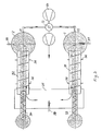
- the device according to FIG. 1 has two regenerators 1, 2 designed as shaft reactors, which are connected to one another at their upper end via a screw tube furnace 3. Approximately in the middle of the screw tube furnace 3 there is a filler neck with a lock 4, through which the solids to be treated are filled.
- a rotatable screw 5 with screw blades 6 is arranged inside the screw tube furnace 3.
- a bed 7, 8 designed as a moving bed, which serves for heat regeneration, discharge devices 9, 10 designed as locks being provided on the bottom of the regenerators 1, 2.
- Burners 16, 17 are arranged laterally in the upper region of the regenerators above the beds 7, 8.
- the solid for example stones or pellets
- the screw blades 6 of the screw 5 are arranged such that they convey the solid in approximately equal amounts from the center to the two ends of the screw 5 and mix at the same time.
- the main burning process takes place with the release of possible harmful gases.
- the largely burned solid falls into the two regenerators 1, 2 and forms the regeneration bed 7, 8.
- cooled solids are discharged from the bottom via the discharge devices 9, 10 .
- the combustion air required for the combustion process is introduced via one of the lines 11, 12 into one of the regenerators 1, 2, which are supplied by the blower is delivered via the four-way valve.
- the air flows, for example, through the moving bed 7 of the regenerator 1, which is indicated by the black arrows, and heats up on the solids of the moving bed 7.
- the air has largely reached the temperature of the escaping gases.
- the air is further heated by the burner 16 to such an extent that the solid can burn in the screw tube furnace 2.
- the combustion gases can only escape through the bed 2 of the regenerator 8, whereby they give off most of their heat to the bed 8.
- the gases emerging at the bottom of the regenerator 2 escape through the four-way valve 13 and the outlet 15 and can be sucked off by an additional blower.
- the four-way valve 13 is changed over and the air now flows through the previously heated bed 8 of the regenerator 2, which is thereby cooled again.
- the burner 17 now takes over the additional heating of the air to the temperature necessary for the fire.
- Fixed cycle times can be set for the mutual switching of the air supply in the respective regenerator 1, 2.
- a control unit can also be provided that switches the four-way valve.
- the temperature of the gas emerging from the bottom of the respective regenerator 1, 2 is measured, the changeover taking place when the temperature of the emerging gases falls below a certain predetermined value.
- the supply of fuel by the burners 16, 17 can be reduced in accordance with the proportion of the combustible components. If the combustible contains more combustible constituents than are required for burning, overheating could result. In this case, cooling is carried out, which is implemented by built-in heat exchangers or by injecting water.
- metal-containing pellets can also be introduced as a solid, which pellets are reduced in the screw tube furnace 3. Then, instead of the air, CO and H2-containing generator gas is introduced into the bottom region of the regenerators 1, 2, which is preheated by the beds 7, 8 of the regenerators. Pre-heated air is then blown in instead of fuel, which leads to partial combustion of the generator gas and provides the heat of reaction.
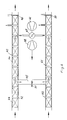
- FIG. 2 shows a further exemplary embodiment of the device for the thermal treatment of solids, in which a moving floor furnace is used.
- the same reference numerals are used for the same parts.
- the solids are also poured via a lock 4 onto the center of a platform 20 on which there is a moving floor 21 with differently directed pushing wedges 22, 23.
- the moving floor 21 By moving the moving floor 21, the solids to be burned are mixed and gradually moved to the two ends 24, 25, of which they fall into the two regenerators 1, 2.
- Distribution troughs 26 are provided for the uniform distribution of the fired solids in the regenerators 1, 2.
- the heat is regenerated in accordance with the exemplary embodiment according to FIG. 1.
- burners 27, 28, 29, 30 or nozzles for supplying air are provided at several different points.
- FIG. 3 shows a further exemplary embodiment in a top view of the device for the thermal treatment of solids, in which two rotary tube furnaces 31, 32 are used.
- the solids to be burned are fed evenly into the two rotary kilns 31, 32 via two feed devices 33, 34.
- the rotary kilns 31, 32 are connected to one another via a hot gas duct 35 and are movably sealed with respect to the hot gas duct 35 and against the regenerators 1, 2 by means of sealing sleeves 36.
- the solids are conveyed to the regenerators 1, 2 by the rotation of the rotary kilns 31, 32.
- the burners 37, 38 are arranged behind the rotary kilns 31, 32 in front of the regenerators 1, 2, but a burner 39 can also be provided in the hot gas duct 35, the burners 37, 38, 39 being actuated alternately.
- the heat regeneration is carried out in accordance with the embodiment of FIG. 1.
- Fig. 4 shows an embodiment with two tunnel kilns 40, 41, which are particularly suitable for firing ceramics.
- the tunnel ovens 40, 41 are connected to feed tunnels 42, 43, the solids to be burned being transported slowly on tunnel wagons 44 via the feed tunnels 42, 43 through tunnel ovens 40, 41.
- Behind the feed tunnels 42, 43, the tunnel ovens 40, 41 are connected to one another via a hot gas duct 45.
- the air supply or the supply of the reducing gases corresponds to the arrangements according to FIGS.
- lock chambers 49, 50 are provided, through which the fired solids and cooled in the tunnel section are discharged.
- the lock chambers 49, 50 are necessary because there is an overpressure or underpressure in front of them. Locks can also be provided in the feed tunnels 42, 43.
- the blower output of the two blowers 46, 48 can, however, be coordinated with one another in such a way that the hot gas duct 45, which connects the two tunnel ovens 40, 41, has approximately the same pressure as in the environment, so that no locks are necessary and through the open feed tunnels 42, 43 no incorrect air can be sucked in or fuel gases can escape. In order to prevent fuel gases from escaping, it is even better to set a low negative pressure in relation to the surroundings, so that a small amount of fresh air is drawn in through the tunnel openings.
- the combustion air supplied via the four-way valve 47 heats up on the fired solids the loaded tunnel car 44, which slowly moves to the locks 49, 50. At the end of the respective tunnel furnace 40, they are further heated by the burner 51 in the hot gas duct 45, so that the solids present on the tunnel carriage 44 can be burned. The combustion gases then cool down on the solids in the other tunnel kiln.
- the heat regeneration thus corresponds to that from the preceding exemplary embodiments, the loaded tunnel wagons being guided through the tunnel furnaces 40, 41 forming the regenerators instead of the bed.
- the tunnel car 44 are loaded so that the solids are evenly flowed through.
Landscapes
- Engineering & Computer Science (AREA)
- Mechanical Engineering (AREA)
- General Engineering & Computer Science (AREA)
- Chemical & Material Sciences (AREA)
- Combustion & Propulsion (AREA)
- Muffle Furnaces And Rotary Kilns (AREA)
- Processing Of Solid Wastes (AREA)
- Waste-Gas Treatment And Other Accessory Devices For Furnaces (AREA)
- Heat Treatments In General, Especially Conveying And Cooling (AREA)
- Tunnel Furnaces (AREA)
- Treatment Of Sludge (AREA)
- Feeding, Discharge, Calcimining, Fusing, And Gas-Generation Devices (AREA)
Claims (18)
- Procédé de traitement thermique de solides dans un milieu oxydant ou réducteur, par l'utilisation de régénérateurs et d'un four, dans lequel les gaz oxydants et respectivement réducteurs sont réciproquement introduits dans les régénérateurs et évacués à nouveau sous la forme de gaz résiduaires pour un traitement principal thermique des substances solides et après passage à travers le four et les régénérateurs, le sens d'écoulement des gaz oxydants et respectivement réducteurs admis étant commuté de manière cyclique, caractérisé en ce que les substances solides sont introduites dans la zone- très chaude du four, sont soumises au traitement thermique principal et sont, après le traitement thermique principal, transportées en deux quantités partielles dans les régénérateurs, une substance solide thermiquement traitée, refroidie, étant prélevée des régénérateurs, et en ce que les gaz oxydants et respectivement réducteurs introduits réciproquement dans les régénérateurs sont chauffés sur les substances solides soumises au traitement thermique principal.
- Procédé suivant la revendication 1, caractérisé en ce que les substances solides traversent les régénérateurs d'une manière continue dans un lit migrant.
- Procédé suivant la revendication 1, caractérisé en ce que les substances solides traversent les régénérateurs en plusieurs quantités partielles.
- Procédé suivant l'une des revendications 1 à 3, caractérisé en ce que la température des gaz sortant du régénérateur correspondant est mesurée et en ce que, en fonction de cette température, l'introduction réciproque de l'air de combustion et respectivement des gaz réducteurs est commandée.
- Procédé suivant l'une des revendications 1 à 4, caractérisé en ce que les substances solides sont agglomérées en boulettes et contiennent des oxydes métalliques, le gaz réducteur introduit, chauffé dans le régénérateur correspondant et réalisé sous la forme d'un gaz de gazogène étant, avec un débit d'air inférieur à la stoechiométrie, chauffé de manière poursuivie à une température nécessaire pour la réduction.
- Procédé suivant l'une des revendications 1 à 4, caractérisé en ce que les substances solides sont brûlées par des gaz de combustion oxydants, l'air de combustion introduit, chauffé dans le régénérateur correspondant, étant, avec une addition de combustible, chauffé de manière poursuivie à une température nécessaire pour la combustion.
- Procédé suivant l'une des revendications 5 et 6, caractérisé en ce que l'air nécessaire à la réduction ou respectivement le combustible nécessaire à la combustion est amené en plusieurs endroits différents pour obtenir un chauffage uniforme.
- Procédé suivant l'une des revendications 5 à 7, caractérisé en ce que l'addition d'air ou respectivement de combustible est commandée de manière réciproque en fonction de l'apport d'air de combustion ou respectivement de gaz réducteurs dans le régénérateur correspondant.
- Dispositif pour le traitement thermique de substances solides dans un milieu oxydant ou respectivement réducteur suivant la revendication 1, comprenant un four, dans lequel un traitement thermique principal des substances solides est effectué, et deux régénérateurs reliés au four, dans lesquels des gaz oxydants et respectivement réducteurs sont réciproquement introduits par l'intermédiaire de conduits d'entrée et respectivement de sortie agencés aux extrémités des régénérateurs opposées au four, sont utilisés pour le traitement thermique principal dans le four et sont évacués, sous la forme de gaz résiduaires, après passage à travers le four et les régénérateurs, caractérisé en ce que le four (3; 31, 32; 40, 41) présente un dispositif d'alimentation (4) pour amener les substances solides directement dans le four et un dispositif de transport (6, 22) qui achemine les substances solides soumises au traitement thermique principal en deux courants partiels dans les régénérateurs (1, 2; 40, 41), et en ce que chaque régénérateur (1, 2; 40, 41) est raccordé, à son extrémité opposée au four, à un dispositif d'évacuation (9, 10) pour la substance solide thermiquement traitée.
- Dispositif suivant la revendication 9, caractérisé en ce qu'on prévoit une vanne à quatre voies (13, 45) par laquelle les gaz oxydants et respectivement réducteurs peuvent être amenés et les gaz résiduaires sortant des régénérateurs (1, 2; 40, 41) être évacués.
- Dispositif suivant l'une des revendications 9 et 10, caractérisé en ce que le dispositif d'alimentation (4) pour les substances solides est agencé au milieu du four reliant les régénérateurs et en ce que les régénérateurs (1, 2) sont réalisés sous la forme de réacteurs en forme de puits, le dispositif d'évacuation (9, 10) pour les substances solides formant un lit migratoire et soumises au traitement thermique principal étant agencé au fond de chaque réacteur en forme de puits.
- Dispositif suivant la revendication 11, caractérisé en ce que le four reliant les régénérateurs (1, 2) est réalisé sous la forme d'un réacteur tubulaire à vis (3), les pales de la vis en rotation formant le dispositif de transport.
- Dispositif suivant la revendication 11, caractérisé en ce que le four reliant les régénérateurs (1, 2) est réalisé sous la forme d'un réacteur à fond poussant (21), des coins de poussée déplacés provoquant l'avancement des substances solides vers les régénérateurs.
- Dispositif suivant la revendication 13, caractérisé en ce que des canaux de répartition (26) sont prévus en dessous du réacteur à fond poussant (21) pour répartir de manière uniforme les substances solides dans les régénérateurs (1, 2).
- Dispositif suivant l'une des revendications 9 à 11, caractérisé en ce que le four reliant les régénérateurs (1, 2) est constitué d'un double four tubulaire rotatif (31, 32) pourvu d'un canal de liaison (35) entre les fours tubulaires rotatifs (31, 32), chaque four tubulaire rotatif (31, 32) présentant un dispositif d'alimentation (33, 34), et en ce que, pendant le traitement thermique principal, les substances solides peuvent être transportées dans les deux régénérateurs par des dispositifs de transport des fours tubulaires rotatifs, en deux parties approximativement égales.
- Dispositif suivant l'une des revendications 8 et 9, caractérisé en ce que les régénérateurs sont réalisés sous la forme de fours tunnels (40, 41) parallèles et en ce que le four reliant les régénérateurs (40, 41) est constitué de zones partielles des fours tunnels (40, 41) entre lesquelles un canal de liaison (45) est prévu.
- Dispositif suivant la revendication 16, caractérisé en ce que, pour l'amenée de l'air de combustion et pour l'aspiration des gaz résiduaires, on prévoit des ventilateurs (46, 48) dont les puissances sont accordées l'une sur l'autre de telle façon qu'il règne dans le canal de liaison (45) approximativement la même pression que dans l'environnement.
- Dispositif suivant la revendication 17, caractérisé en ce que les puissances des deux ventilateurs (46, 48) sont accordées l'une sur l'autre de telle façon qu'une faible pression réduite par rapport à l'environnement soit prévue dans le canal de liaison (45).
Priority Applications (1)
| Application Number | Priority Date | Filing Date | Title |
|---|---|---|---|
| AT89730110T ATE92613T1 (de) | 1988-05-09 | 1989-04-27 | Verfahren und vorrichtung zur thermischen behandlung von feststoffen. |
Applications Claiming Priority (2)
| Application Number | Priority Date | Filing Date | Title |
|---|---|---|---|
| DE3816492A DE3816492A1 (de) | 1988-05-09 | 1988-05-09 | Verfahren und vorrichtung zur thermischen behandlung von feststoffen |
| DE3816492 | 1988-05-09 |
Publications (3)
| Publication Number | Publication Date |
|---|---|
| EP0342148A2 EP0342148A2 (fr) | 1989-11-15 |
| EP0342148A3 EP0342148A3 (en) | 1990-03-28 |
| EP0342148B1 true EP0342148B1 (fr) | 1993-08-04 |
Family
ID=6354374
Family Applications (1)
| Application Number | Title | Priority Date | Filing Date |
|---|---|---|---|
| EP89730110A Expired - Lifetime EP0342148B1 (fr) | 1988-05-09 | 1989-04-27 | Procédé et dispositif pour le traitement thermique de solides |
Country Status (4)
| Country | Link |
|---|---|
| EP (1) | EP0342148B1 (fr) |
| AT (1) | ATE92613T1 (fr) |
| DE (2) | DE3816492A1 (fr) |
| ES (1) | ES2043086T3 (fr) |
Families Citing this family (2)
| Publication number | Priority date | Publication date | Assignee | Title |
|---|---|---|---|---|
| DE4224778A1 (de) * | 1992-07-27 | 1994-02-03 | Horst Dr Grochowski | Entsorgungsverfahren für Umweltgifte |
| CN111288438B (zh) * | 2020-03-26 | 2021-09-24 | 江苏大学 | 一种流化床燃烧炉和燃烧方法 |
Family Cites Families (7)
| Publication number | Priority date | Publication date | Assignee | Title |
|---|---|---|---|---|
| DE59234C (de) * | 1889-10-29 | 1891-10-12 | AKTIEN-GESELLSCHAFT FÜR GLASINDUSTRIE VORM. FRIEDR. SIEMENS in Dresden | Ununterbrochen arbeitender Zwillings-Schachtofen mit Regenerativ-Feuerung mit festem oder flüssigem Brennstoff und FRIEDRICH SlEMENSscher freier Flammenentfaltung |
| DE320439C (de) * | 1913-12-10 | 1920-04-22 | Antony Gauchet | Verfahren nebst Doppelofen zur Ausnutzung der Abgaswaerme in Kupoloefen |
| DE601795C (de) * | 1931-02-05 | 1934-08-24 | Mathias Fraenkl | Zweischacht-Schmelz- und -Reduktionsofen und Verfahren zu seinem Betriebe |
| US2544091A (en) * | 1948-05-10 | 1951-03-06 | Jordan Res Lab Inc | Method of melting |
| US2959629A (en) * | 1956-11-19 | 1960-11-08 | Pure Oil Co | Fixed bed, pyrolytic, hydrocarbon conversion process employing a granular, heat-transfer medium |
| DE1154238B (de) * | 1958-10-02 | 1963-09-12 | Alois Schmidt | Verfahren zum Schmelzen von Metallen, Verhuetten von Erzen od. dgl. und Schachtofen zur Durchfuehrung dieses Verfahrens |
| SE395714B (sv) * | 1974-02-20 | 1977-08-22 | Skf Ind Trading & Dev | Sett och anordning for framstellning av metall ur oxidiskt material |
-
1988
- 1988-05-09 DE DE3816492A patent/DE3816492A1/de not_active Withdrawn
-
1989
- 1989-04-27 EP EP89730110A patent/EP0342148B1/fr not_active Expired - Lifetime
- 1989-04-27 AT AT89730110T patent/ATE92613T1/de not_active IP Right Cessation
- 1989-04-27 ES ES89730110T patent/ES2043086T3/es not_active Expired - Lifetime
- 1989-04-27 DE DE8989730110T patent/DE58905101D1/de not_active Expired - Fee Related
Also Published As
| Publication number | Publication date |
|---|---|
| EP0342148A2 (fr) | 1989-11-15 |
| DE58905101D1 (de) | 1993-09-09 |
| ES2043086T3 (es) | 1993-12-16 |
| EP0342148A3 (en) | 1990-03-28 |
| DE3816492A1 (de) | 1989-11-16 |
| ATE92613T1 (de) | 1993-08-15 |
Similar Documents
| Publication | Publication Date | Title |
|---|---|---|
| DE3788871T2 (de) | Verfahren zur abfallverarbeitung sowie drehofen für diesen zweck. | |
| EP0306695B1 (fr) | Dispositif de génération de gaz chaud avec postcombustion thermique | |
| DE69228607T2 (de) | Verfahren und Vorrichtung zum kontinuierlichen Schrottvorwärmen | |
| EP1334954B1 (fr) | Installation de préparation de clinker de ciment | |
| DE3012167C2 (fr) | ||
| DE2636374C2 (de) | Verfahren und Vorrichtung zur Reinigung von Abgas | |
| DE2325468A1 (de) | Vorrichtung zum sintern von zement und aehnlichen stoffen | |
| EP1146304A1 (fr) | Four à deux chambres pour la fusion par immersion de déchets d'alumium contaminés | |
| EP0854339A1 (fr) | Procédé et installation pour le traitement thermique de charges finement granulées | |
| DE3444073A1 (de) | Verfahren und anlage zum verbrennen von abfaellen wie haus-, industrie- und sondermuell | |
| DE2614952C2 (de) | Verfahren und Vorrichtung zum kontinuierlichen Brennen von Kohlenstofformlingen | |
| DE2349932A1 (de) | Verfahren und vorrichtung zur waermebehandlung von material | |
| EP0716052A1 (fr) | Procédé et installation pour le refroidissement et la fabrication de matériaux en vrac | |
| EP4308867B1 (fr) | Procédé pour la cuisson d'un matériau contenant du carbonate dans un four à cuve | |
| DE19818953C1 (de) | Verfahren und Anordnung zum Schmelzen von Glas in U-Flammen und Querflammenwannenöfen unter Reduzierung der Gehalte an NO¶x¶ und CO in den Abgasen | |
| CH638296A5 (de) | Verfahren und anlage zum brennen von karbonhaltigen rohstoffen mittels zerkleinerten festen brennstoffen in einem gleichstrom-regenerativ-schachtofen. | |
| DE2810043C2 (fr) | ||
| DE2501457A1 (de) | Drehofenanlage | |
| DE1927558B1 (de) | Verfahren und Vorrichtung zur Erzeugung von Eisenschwamm aus oxydischen Eisenerzen | |
| DE2657239A1 (de) | Regenerativ-gleichstrombrennverfahren fuer die kalkherstellung | |
| EP0704658B1 (fr) | Procédé de traítement thermique des matières résiduaire, notamment des ordures | |
| EP0039798A1 (fr) | Procédé pour la cuisson et le frittage des terres de lavage | |
| DE1433339A1 (de) | Verfahren zum Hartbrennen von Pellets | |
| EP0342148A2 (fr) | Procédé et dispositif pour le traitement thermique de solides | |
| DE10051648A1 (de) | Verfahren und Schacht-Schmelz-Vergaser zur thermischen Behandlung und Verwertung von Abfallstoffen |
Legal Events
| Date | Code | Title | Description |
|---|---|---|---|
| PUAI | Public reference made under article 153(3) epc to a published international application that has entered the european phase |
Free format text: ORIGINAL CODE: 0009012 |
|
| AK | Designated contracting states |
Kind code of ref document: A2 Designated state(s): AT BE CH DE ES FR GB GR IT LI LU NL SE |
|
| PUAL | Search report despatched |
Free format text: ORIGINAL CODE: 0009013 |
|
| AK | Designated contracting states |
Kind code of ref document: A3 Designated state(s): AT BE CH DE ES FR GB GR IT LI LU NL SE |
|
| 17P | Request for examination filed |
Effective date: 19900817 |
|
| 17Q | First examination report despatched |
Effective date: 19920124 |
|
| ITF | It: translation for a ep patent filed | ||
| GRAA | (expected) grant |
Free format text: ORIGINAL CODE: 0009210 |
|
| AK | Designated contracting states |
Kind code of ref document: B1 Designated state(s): AT BE CH DE ES FR GB GR IT LI LU NL SE |
|
| PG25 | Lapsed in a contracting state [announced via postgrant information from national office to epo] |
Ref country code: GR Free format text: LAPSE BECAUSE OF FAILURE TO SUBMIT A TRANSLATION OF THE DESCRIPTION OR TO PAY THE FEE WITHIN THE PRESCRIBED TIME-LIMIT Effective date: 19930804 |
|
| REF | Corresponds to: |
Ref document number: 92613 Country of ref document: AT Date of ref document: 19930815 Kind code of ref document: T |
|
| REF | Corresponds to: |
Ref document number: 58905101 Country of ref document: DE Date of ref document: 19930909 |
|
| GBT | Gb: translation of ep patent filed (gb section 77(6)(a)/1977) |
Effective date: 19930913 |
|
| ET | Fr: translation filed | ||
| REG | Reference to a national code |
Ref country code: ES Ref legal event code: FG2A Ref document number: 2043086 Country of ref document: ES Kind code of ref document: T3 |
|
| PGFP | Annual fee paid to national office [announced via postgrant information from national office to epo] |
Ref country code: NL Payment date: 19940430 Year of fee payment: 6 |
|
| PGFP | Annual fee paid to national office [announced via postgrant information from national office to epo] |
Ref country code: GB Payment date: 19940520 Year of fee payment: 6 Ref country code: FR Payment date: 19940520 Year of fee payment: 6 |
|
| PGFP | Annual fee paid to national office [announced via postgrant information from national office to epo] |
Ref country code: DE Payment date: 19940524 Year of fee payment: 6 |
|
| PGFP | Annual fee paid to national office [announced via postgrant information from national office to epo] |
Ref country code: AT Payment date: 19940525 Year of fee payment: 6 |
|
| PGFP | Annual fee paid to national office [announced via postgrant information from national office to epo] |
Ref country code: SE Payment date: 19940530 Year of fee payment: 6 |
|
| PGFP | Annual fee paid to national office [announced via postgrant information from national office to epo] |
Ref country code: LU Payment date: 19940531 Year of fee payment: 6 Ref country code: ES Payment date: 19940531 Year of fee payment: 6 Ref country code: BE Payment date: 19940531 Year of fee payment: 6 |
|
| PLBE | No opposition filed within time limit |
Free format text: ORIGINAL CODE: 0009261 |
|
| STAA | Information on the status of an ep patent application or granted ep patent |
Free format text: STATUS: NO OPPOSITION FILED WITHIN TIME LIMIT |
|
| PGFP | Annual fee paid to national office [announced via postgrant information from national office to epo] |
Ref country code: CH Payment date: 19940624 Year of fee payment: 6 |
|
| 26N | No opposition filed | ||
| EPTA | Lu: last paid annual fee | ||
| EAL | Se: european patent in force in sweden |
Ref document number: 89730110.7 |
|
| PG25 | Lapsed in a contracting state [announced via postgrant information from national office to epo] |
Ref country code: LU Free format text: LAPSE BECAUSE OF NON-PAYMENT OF DUE FEES Effective date: 19950427 Ref country code: GB Effective date: 19950427 Ref country code: AT Effective date: 19950427 |
|
| PG25 | Lapsed in a contracting state [announced via postgrant information from national office to epo] |
Ref country code: SE Effective date: 19950428 Ref country code: ES Free format text: LAPSE BECAUSE OF NON-PAYMENT OF DUE FEES Effective date: 19950428 |
|
| PG25 | Lapsed in a contracting state [announced via postgrant information from national office to epo] |
Ref country code: LI Effective date: 19950430 Ref country code: CH Effective date: 19950430 Ref country code: BE Effective date: 19950430 |
|
| BERE | Be: lapsed |
Owner name: MICHEL-KIM HERWIG Effective date: 19950430 |
|
| PG25 | Lapsed in a contracting state [announced via postgrant information from national office to epo] |
Ref country code: NL Effective date: 19951101 |
|
| REG | Reference to a national code |
Ref country code: CH Ref legal event code: PL |
|
| PG25 | Lapsed in a contracting state [announced via postgrant information from national office to epo] |
Ref country code: FR Effective date: 19951229 |
|
| NLV4 | Nl: lapsed or anulled due to non-payment of the annual fee |
Effective date: 19951101 |
|
| GBPC | Gb: european patent ceased through non-payment of renewal fee |
Effective date: 19950427 |
|
| PG25 | Lapsed in a contracting state [announced via postgrant information from national office to epo] |
Ref country code: DE Effective date: 19960103 |
|
| EUG | Se: european patent has lapsed |
Ref document number: 89730110.7 |
|
| REG | Reference to a national code |
Ref country code: FR Ref legal event code: ST |
|
| REG | Reference to a national code |
Ref country code: ES Ref legal event code: FD2A Effective date: 19990503 |
|
| PG25 | Lapsed in a contracting state [announced via postgrant information from national office to epo] |
Ref country code: IT Free format text: LAPSE BECAUSE OF NON-PAYMENT OF DUE FEES;WARNING: LAPSES OF ITALIAN PATENTS WITH EFFECTIVE DATE BEFORE 2007 MAY HAVE OCCURRED AT ANY TIME BEFORE 2007. THE CORRECT EFFECTIVE DATE MAY BE DIFFERENT FROM THE ONE RECORDED. Effective date: 20050427 |