EP0342178B1 - Dispositif pour monter une bague de laminage sur un arbre de laminage - Google Patents
Dispositif pour monter une bague de laminage sur un arbre de laminage Download PDFInfo
- Publication number
- EP0342178B1 EP0342178B1 EP19890890045 EP89890045A EP0342178B1 EP 0342178 B1 EP0342178 B1 EP 0342178B1 EP 19890890045 EP19890890045 EP 19890890045 EP 89890045 A EP89890045 A EP 89890045A EP 0342178 B1 EP0342178 B1 EP 0342178B1
- Authority
- EP
- European Patent Office
- Prior art keywords
- ring
- roller shaft
- pressure
- rolling
- friction
- Prior art date
- Legal status (The legal status is an assumption and is not a legal conclusion. Google has not performed a legal analysis and makes no representation as to the accuracy of the status listed.)
- Expired - Lifetime
Links
- 239000002783 friction material Substances 0.000 claims description 6
- 239000011248 coating agent Substances 0.000 claims 1
- 238000000576 coating method Methods 0.000 claims 1
- 238000005096 rolling process Methods 0.000 description 41
- 230000036316 preload Effects 0.000 description 6
- 230000005540 biological transmission Effects 0.000 description 5
- 239000002184 metal Substances 0.000 description 5
- 229910052751 metal Inorganic materials 0.000 description 5
- 238000010276 construction Methods 0.000 description 2
- 239000000463 material Substances 0.000 description 2
- 229920002430 Fibre-reinforced plastic Polymers 0.000 description 1
- 239000004952 Polyamide Substances 0.000 description 1
- 229910000831 Steel Inorganic materials 0.000 description 1
- 230000015572 biosynthetic process Effects 0.000 description 1
- 230000006835 compression Effects 0.000 description 1
- 238000007906 compression Methods 0.000 description 1
- 230000007812 deficiency Effects 0.000 description 1
- 230000001419 dependent effect Effects 0.000 description 1
- 230000000694 effects Effects 0.000 description 1
- 239000011151 fibre-reinforced plastic Substances 0.000 description 1
- 238000003754 machining Methods 0.000 description 1
- 238000004519 manufacturing process Methods 0.000 description 1
- 239000007769 metal material Substances 0.000 description 1
- 229920002647 polyamide Polymers 0.000 description 1
- 238000003892 spreading Methods 0.000 description 1
- 239000010959 steel Substances 0.000 description 1
- UONOETXJSWQNOL-UHFFFAOYSA-N tungsten carbide Chemical compound [W+]#[C-] UONOETXJSWQNOL-UHFFFAOYSA-N 0.000 description 1
Images
Classifications
-
- B—PERFORMING OPERATIONS; TRANSPORTING
- B21—MECHANICAL METAL-WORKING WITHOUT ESSENTIALLY REMOVING MATERIAL; PUNCHING METAL
- B21B—ROLLING OF METAL
- B21B27/00—Rolls, roll alloys or roll fabrication; Lubricating, cooling or heating rolls while in use
- B21B27/02—Shape or construction of rolls
- B21B27/03—Sleeved rolls
- B21B27/035—Rolls for bars, rods, rounds, tubes, wire or the like
Definitions
- the invention relates to a device for fastening a roller ring on the freely projecting end of a cantilevered roller shaft, consisting of two pressure rings axially clamping the roller ring between them, one of which is axially supported on the roller shaft and the other on a clamping device, and from a wedge sleeve axially displaceable by means of an actuator between the roller ring and the conical roller shaft in the region of the roller ring.
- the free end of the roller shaft carries an end cap with an external thread for receiving a pretensioning nut, with the aid of which the rolling ring made of hard metal, which is provided with a corresponding rolling caliber and is made of hard metal, between two Thrust rings are subjected to an axial prestress.
- This axial pressure preload considerably reduces the notch effects in the area of the rolling caliber that occur during the rolling process.
- the hard metal rolling ring is additionally subjected to a prestress in the radial direction, with the aid of a wedge sleeve between the rolling ring and the conical roller shaft in the area of the rolling ring.
- This wedge sleeve is driven into the annular gap between the rolling ring and the conical part of the roller shaft by means of adjusting screws held in the end cap in an adjustable manner.
- the torque transmission from the roller shaft to the roller ring takes place non-positively on the one hand via the wedge sleeve and on the other hand via the two pressure rings that axially clamp the compression ring and is therefore dependent on the respectively applied clamping forces.
- tungsten carbide rolling rings are sensitive to tension, the preload of the rolling rings cannot easily be increased to a level that ensures safe rotation of the rolling rings even in the event of impact loads, without increasing the risk of rolling ring breaks.
- a device has become known (US-A-3 727 957) in which, instead of the pressure ring acted upon by the tensioning device, a pressure bracket is used to apply an axial pretension to the roller ring, which pushes through the roller shaft in a transverse bore and with his leg ends projecting over the roller shaft engages in radial driver grooves on the end face of the rolling ring.
- a pressure bracket is used to apply an axial pretension to the roller ring, which pushes through the roller shaft in a transverse bore and with his leg ends projecting over the roller shaft engages in radial driver grooves on the end face of the rolling ring.
- the invention is therefore based on the object to avoid these deficiencies and to improve a device of the type described above with simple means so that a safe rotation of the rolling ring can be guaranteed by the roller shaft without having to accept an unacceptable stress on the rolling ring .
- the invention achieves the stated object in that a friction ring is provided between the rolling ring and at least one of the two pressure rings and in that the friction ring-side pressure ring is seated on the roller shaft preferably in a rotationally fixed manner via a multi-groove connection.
- the torque that can be transmitted between the pressure ring and the roller ring can be increased considerably with a constant axial preload force, or the axial preload force can be reduced accordingly at a predetermined maximum transferable torque, so that the risk of overstressing of the rolling ring according to the clamping of the rolling ring necessary for a rotary drive can be excluded.
- a prerequisite for this, however, is that the pressure ring acting on the rolling ring via the friction ring is connected in a rotationally fixed manner to the roller shaft, which can be ensured in an advantageous manner by a multi-groove connection.
- This multi-slot connection is provided between structural parts which are not susceptible to wear and which, moreover, consist of a comparatively easy-to-machine steel material, so that the additional effort given by this multi-slot connection is hardly significant.
- the slotted wedge sleeve consists of a friction material or has a friction lining and is preferably connected to the shaft in a rotationally fixed but axially displaceable manner via a multi-groove connection.
- a considerable torque can also be transmitted from the roller shaft to the rolling ring via the wedge sleeve without fear of inadmissible radial stresses in the rolling ring, because the frictional connection increases due to the material-related increase in friction is improved accordingly.
- the wedge sleeve which is to be slotted for better spreading apart, itself consists of a friction material or carries a suitable friction lining.
- a fiber-reinforced plastic with a high coefficient of friction can be used as the friction material for the wedge sleeve.
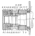
- the roller shaft 1 which is mounted on the fly in the usual way, carries in the region of its freely projecting end 2 a rolling ring 3 made of hard metal with corresponding rolling calibres 4 for the production of profile wires or rod-shaped profiles. Between this rolling ring 3 and the roller shaft 1, which has a conical section 5 in the area of the rolling ring 3, a wedge sleeve 7 is provided with axial slots 6, which on the one hand ensures centering and on the other hand provides a radial prestressing of the rolling ring 3.
- This wedge sleeve 7 forms an annular shoulder 8, act on the pressure plunger 9 distributed over the circumference, which can be acted upon by an actuator formed by an annular piston 10, around the wedge sleeve 7 with a predetermined force in the annular gap between the roller shaft 1 and the roller ring 3 to collect.
- the axial holding of the rolling ring 3 takes place between two pressure rings 11 and 12, of which one pressure ring 11 is supported on a shaft shoulder 13, while the other pressure ring 12 is connected to a tensioning device formed by an annular piston 14.
- the arrangement is such that the one can be acted upon separately Annular pistons 10 and 14 are inserted into two concentric annular grooves 15 and 16 of a carrier 17 fastened on the roller shaft end 2, which is designed as a screw-on end nut 18.
- the pressure rams 9 for the axial application of the wedge sleeve 7 in the passage guides 19 of the pressure ring 12 are slidably held in a stop-limited manner because they have a head 20 projecting beyond the passage guides, which is covered by a pressure transmission ring 21 axially displaceable in the pressure ring 12 becomes.
- a pressure transmission ring 21 axially displaceable in the pressure ring 12 becomes.
- the latter is provided with a circumferential groove 22 into which stop screws 23 distributed over the circumference and held in the pressure ring 12 engage.
- This measure achieves a structural unit which considerably simplifies the replacement of the rolling ring 3, because not only the rolling ring 3 but also the wedge sleeve 2 becomes freely accessible when the pressure ring 12 is removed.
- the rolling ring 3 can be preloaded independently of one another in the radial and in the axial direction, because the annular pistons 10 and 14 act independently of one another on the pressure ring 12 and the pressure transmission ring 21.
- a friction ring 24 is provided between the pressure ring 12 and the roller ring 3, which, with a corresponding axial contact pressure for the desired frictional connection between the pressure ring 12 and the rolling ring 3 ensures.
- a prerequisite for the desired torque transmission is that there is a rotationally fixed connection between the pressure ring 12 and the end 2 of the roller shaft 1.
- a multi-groove connection 25 can be provided between the pressure ring 12 and the roller shaft 1.
- the spline sleeve 7 can also be mounted in a rotationally fixed but axially displaceable manner on the shaft end 2 via a multi-slot connection 26, the connection ring 8 being particularly recommended for the arrangement of this multi-slot connection.
- the wedge sleeve 7 is made of a friction material, for example a fiber-reinforced polyamide, then a considerable proportion of the torque can also be transmitted to the rolling ring 3 via the wedge sleeve 7 without fear of exceeding the permissible radial preload of the rolling ring 3.
Landscapes
- Physics & Mathematics (AREA)
- Geometry (AREA)
- Engineering & Computer Science (AREA)
- Mechanical Engineering (AREA)
- Reduction Rolling/Reduction Stand/Operation Of Reduction Machine (AREA)
Claims (2)
- Dispositif qui, pour fixer un anneau (3) de laminage sur le bout (2) libre en saillie d'un arbre (1) de cylindre monté en porte-à-faux, se compose de deux bagues (11, 12) de serrage qui serrent entre elles l'anneau (3) de laminage dans le sens axial et dont l'une (11) prend axialement appui sur l'arbre (1) du cylindre et l'autre (12) sur un dispositif (14, 17) de serrage, et d'une douille (7) cunéiforme pouvant être déplacée dans le sens axial au moyen d'un mécanisme (10) de réglage entre l'anneau (3) de laminage et l'arbre (1) de cylindre qui est conique dans la zone de l'anneau (1) de laminage, caractérisé par le fait qu'un anneau (24) de friction est prévu entre l'anneau (1) de laminage et au moins l'une des bagues (11, 12) de serrage et que la bague (12) de serrage placée côté anneau de friction est montée sur l'arbre (1) du cylindre de manière à ne pas pouvoir tourner, de préférence par l'intermédiaire d'une liaison (25) par cannelures multiples.
- Dispositif suivant la revendication 1, caractérisé par le fait que la douille (7) cunéiforme fendue est composée d'un matériau de friction ou présente un revêtement de friction et est assemblée à l'arbre (1) du cylindre, de préférence par l'intermédiaire d'une liaison (26) par cannelures multiples, de manière à ne pas pouvoir tourner tout en pouvant être déplacée dans le sens axial.
Applications Claiming Priority (2)
| Application Number | Priority Date | Filing Date | Title |
|---|---|---|---|
| AT0124888A AT390572B (de) | 1988-05-13 | 1988-05-13 | Vorrichtung zum befestigen eines walzringes auf einer walzenwelle |
| AT1248/88 | 1988-05-13 |
Publications (3)
| Publication Number | Publication Date |
|---|---|
| EP0342178A2 EP0342178A2 (fr) | 1989-11-15 |
| EP0342178A3 EP0342178A3 (en) | 1990-12-05 |
| EP0342178B1 true EP0342178B1 (fr) | 1993-08-25 |
Family
ID=3509802
Family Applications (1)
| Application Number | Title | Priority Date | Filing Date |
|---|---|---|---|
| EP19890890045 Expired - Lifetime EP0342178B1 (fr) | 1988-05-13 | 1989-02-21 | Dispositif pour monter une bague de laminage sur un arbre de laminage |
Country Status (3)
| Country | Link |
|---|---|
| EP (1) | EP0342178B1 (fr) |
| AT (1) | AT390572B (fr) |
| DE (1) | DE58905357D1 (fr) |
Families Citing this family (4)
| Publication number | Priority date | Publication date | Assignee | Title |
|---|---|---|---|---|
| EP0455082B1 (fr) * | 1990-05-04 | 1994-06-29 | Sms Schloemann-Siemag Aktiengesellschaft | Ligne combinée pour petits fers et fil |
| ITTV20110016A1 (it) * | 2011-02-07 | 2012-08-08 | Pert S R L Con Unico Socio | Macchina per la laminazione a caldo di barre metalliche |
| CN105363793A (zh) * | 2015-12-17 | 2016-03-02 | 重庆麦拓科技有限公司 | 一种轧机及其轧辊与轧辊轴的连接结构 |
| CN115228945B (zh) * | 2022-07-26 | 2025-02-25 | 浙江朋诚科技有限公司 | 一种夹送辊辊环固定结构及其实现方法 |
Family Cites Families (10)
| Publication number | Priority date | Publication date | Assignee | Title |
|---|---|---|---|---|
| US3457733A (en) * | 1967-06-16 | 1969-07-29 | Borg Warner | Torque limiter |
| US3435499A (en) * | 1967-12-22 | 1969-04-01 | American Shear Knife Co | Roll assembly |
| DE1948424A1 (de) * | 1968-10-02 | 1970-04-09 | Okers Styckebruk Ab | Verfahren zum Befestigen von Hartmetall-Rollringen auf Stuetzzylindern |
| SE391566B (sv) * | 1975-06-24 | 1977-02-21 | Asea Ab | Krymp- eller klemforband |
| DE2832966A1 (de) * | 1978-07-27 | 1980-02-21 | Schloemann Siemag Ag | Einrichtung zum drehfesten verbinden von mit wellen oder wellenzapfen umlaufenden maschinenteilen, beispielsweise walzen |
| DD211288A1 (de) * | 1982-11-11 | 1984-07-11 | Landmaschtech Ingbetrieb | Einrichtung zum auswechseln von walzen |
| US4581911A (en) * | 1983-03-07 | 1986-04-15 | Kabushiki Kaisha Kobe Seiko Sho | Cantilever type rolling mill |
| DE3701680C2 (de) * | 1987-01-22 | 1993-10-07 | Schloemann Siemag Ag | Schnellspannvorrichtung für Ringkörper auf dem freien Ende einer fliegend gelagerten Antriebswelle |
| DE8710309U1 (de) * | 1987-07-28 | 1987-09-24 | Giesen, Sonja, 4005 Meerbusch | Konushülse |
| DE3725013A1 (de) * | 1987-07-29 | 1989-02-09 | Schloemann Siemag Ag | Spannvorrichtung fuer ringkoerper auf einer beidseitig gelagerten welle |
-
1988
- 1988-05-13 AT AT0124888A patent/AT390572B/de not_active IP Right Cessation
-
1989
- 1989-02-21 DE DE89890045T patent/DE58905357D1/de not_active Expired - Fee Related
- 1989-02-21 EP EP19890890045 patent/EP0342178B1/fr not_active Expired - Lifetime
Also Published As
| Publication number | Publication date |
|---|---|
| AT390572B (de) | 1990-05-25 |
| DE58905357D1 (de) | 1993-10-07 |
| EP0342178A3 (en) | 1990-12-05 |
| EP0342178A2 (fr) | 1989-11-15 |
| ATA124888A (de) | 1989-11-15 |
Similar Documents
| Publication | Publication Date | Title |
|---|---|---|
| DE2235109C2 (de) | Verbindung zwischen einem Bohrer und einer Spindel | |
| EP0143999B1 (fr) | Unité de tension | |
| DE2621201B2 (de) | Laufrad für eine Strömungsmaschine | |
| DE2151190A1 (de) | Rotierendes schneidwerkzeug fuer eine maschine zum einarbeiten von rillen in beton | |
| EP0342178B1 (fr) | Dispositif pour monter une bague de laminage sur un arbre de laminage | |
| DE10231840B3 (de) | Welle-Nabeverbindung | |
| EP0342179B1 (fr) | Dispositif pour monter une bague de laminage sur un arbre de laminage | |
| DE2528485A1 (de) | Aufloesewalze | |
| DE2639543A1 (de) | Walzscheibenbefestigung | |
| EP2106509B1 (fr) | Frein à disque pour un véhicule automobile et son boîtier | |
| DE3834606C2 (fr) | ||
| DE3876080T2 (de) | Anordnung von fliegend gelagerten walzen. | |
| DE3821445A1 (de) | Walze fuer einen walzenstuhl | |
| DE3142763C2 (de) | Vorrichtung zum Festspannen einer Walzwerkswalze auf einer Trägerwelle | |
| DE69614840T2 (de) | Lösbare nabe für die montage eines drehenden teils auf einer antriebswelle und mit einer lösbaren nabe dieser art versehendes drehendes teil | |
| DE1908942A1 (de) | Befestigung eines Walzringes auf einer Welle mit zugehoerigem Werkzeugsatz | |
| DE3226695A1 (de) | Einrichtung zum verspannen von walzscheiben oder walzringen, vorzugsweise in fliegend gelagerter anordnung | |
| DE2044046A1 (de) | Sicherungsvorrichtung für eine Schleifspindel | |
| DE3400701A1 (de) | Vorrichtung fuer die befestigung eines fahrzeugrades an einem drehbar gelagerten achsteil | |
| EP3523062B1 (fr) | Dispositif de cylindre de laminage pourvu d'un cylindre de laminage et d'un arbre de cylindre | |
| DE3004663C2 (de) | Hobeltriebwerk | |
| DD141466A1 (de) | Vorrichtung zum befestigen von walzscheiben auf antriebswellen | |
| DE2647799C3 (de) | Pelletpresse | |
| DE1811614A1 (de) | Walzenscheibenbefestigung fuer Draht-,Streckreduzierwalzwerke und dergleichen Walzwerksmaschinen | |
| CH508827A (de) | Vorrichtung zum Einstellen des axialen Spiels von Kugel-Spindelgetrieben |
Legal Events
| Date | Code | Title | Description |
|---|---|---|---|
| PUAI | Public reference made under article 153(3) epc to a published international application that has entered the european phase |
Free format text: ORIGINAL CODE: 0009012 |
|
| AK | Designated contracting states |
Kind code of ref document: A2 Designated state(s): DE GB IT SE |
|
| PUAL | Search report despatched |
Free format text: ORIGINAL CODE: 0009013 |
|
| AK | Designated contracting states |
Kind code of ref document: A3 Designated state(s): DE GB IT SE |
|
| 17P | Request for examination filed |
Effective date: 19910118 |
|
| 17Q | First examination report despatched |
Effective date: 19920827 |
|
| GRAA | (expected) grant |
Free format text: ORIGINAL CODE: 0009210 |
|
| AK | Designated contracting states |
Kind code of ref document: B1 Designated state(s): DE GB IT SE |
|
| ITF | It: translation for a ep patent filed | ||
| RAP2 | Party data changed (patent owner data changed or rights of a patent transferred) |
Owner name: VOEST-ALPINE INDUSTRIEANLAGENBAU GMBH |
|
| REF | Corresponds to: |
Ref document number: 58905357 Country of ref document: DE Date of ref document: 19931007 |
|
| GBT | Gb: translation of ep patent filed (gb section 77(6)(a)/1977) |
Effective date: 19931006 |
|
| PLBE | No opposition filed within time limit |
Free format text: ORIGINAL CODE: 0009261 |
|
| STAA | Information on the status of an ep patent application or granted ep patent |
Free format text: STATUS: NO OPPOSITION FILED WITHIN TIME LIMIT |
|
| 26N | No opposition filed | ||
| EAL | Se: european patent in force in sweden |
Ref document number: 89890045.1 |
|
| REG | Reference to a national code |
Ref country code: GB Ref legal event code: IF02 |
|
| PGFP | Annual fee paid to national office [announced via postgrant information from national office to epo] |
Ref country code: GB Payment date: 20040130 Year of fee payment: 16 |
|
| PGFP | Annual fee paid to national office [announced via postgrant information from national office to epo] |
Ref country code: DE Payment date: 20040203 Year of fee payment: 16 |
|
| PGFP | Annual fee paid to national office [announced via postgrant information from national office to epo] |
Ref country code: SE Payment date: 20040204 Year of fee payment: 16 |
|
| PG25 | Lapsed in a contracting state [announced via postgrant information from national office to epo] |
Ref country code: IT Free format text: LAPSE BECAUSE OF NON-PAYMENT OF DUE FEES;WARNING: LAPSES OF ITALIAN PATENTS WITH EFFECTIVE DATE BEFORE 2007 MAY HAVE OCCURRED AT ANY TIME BEFORE 2007. THE CORRECT EFFECTIVE DATE MAY BE DIFFERENT FROM THE ONE RECORDED. Effective date: 20050221 Ref country code: GB Free format text: LAPSE BECAUSE OF NON-PAYMENT OF DUE FEES Effective date: 20050221 |
|
| PG25 | Lapsed in a contracting state [announced via postgrant information from national office to epo] |
Ref country code: SE Free format text: LAPSE BECAUSE OF NON-PAYMENT OF DUE FEES Effective date: 20050222 |
|
| PG25 | Lapsed in a contracting state [announced via postgrant information from national office to epo] |
Ref country code: DE Free format text: LAPSE BECAUSE OF NON-PAYMENT OF DUE FEES Effective date: 20050901 |
|
| EUG | Se: european patent has lapsed | ||
| GBPC | Gb: european patent ceased through non-payment of renewal fee |
Effective date: 20050219 |