EP0342183B1 - Dispositif de graissage pour la boîte à engrenage d'un véhicule à moteur - Google Patents
Dispositif de graissage pour la boîte à engrenage d'un véhicule à moteur Download PDFInfo
- Publication number
- EP0342183B1 EP0342183B1 EP89890137A EP89890137A EP0342183B1 EP 0342183 B1 EP0342183 B1 EP 0342183B1 EP 89890137 A EP89890137 A EP 89890137A EP 89890137 A EP89890137 A EP 89890137A EP 0342183 B1 EP0342183 B1 EP 0342183B1
- Authority
- EP
- European Patent Office
- Prior art keywords
- lubricant
- drive shaft
- valve chamber
- input shaft
- pump
- Prior art date
- Legal status (The legal status is an assumption and is not a legal conclusion. Google has not performed a legal analysis and makes no representation as to the accuracy of the status listed.)
- Expired - Lifetime
Links
- 238000005461 lubrication Methods 0.000 title abstract description 8
- 239000000314 lubricant Substances 0.000 claims abstract description 33
- 230000005540 biological transmission Effects 0.000 claims description 11
- 230000001050 lubricating effect Effects 0.000 claims description 3
- 239000007921 spray Substances 0.000 abstract description 4
- 238000010276 construction Methods 0.000 description 2
- 241000538562 Banjos Species 0.000 description 1
- 206010021580 Inadequate lubrication Diseases 0.000 description 1
- 230000007812 deficiency Effects 0.000 description 1
- 238000005096 rolling process Methods 0.000 description 1
- 238000005507 spraying Methods 0.000 description 1
Images
Classifications
-
- F—MECHANICAL ENGINEERING; LIGHTING; HEATING; WEAPONS; BLASTING
- F16—ENGINEERING ELEMENTS AND UNITS; GENERAL MEASURES FOR PRODUCING AND MAINTAINING EFFECTIVE FUNCTIONING OF MACHINES OR INSTALLATIONS; THERMAL INSULATION IN GENERAL
- F16H—GEARING
- F16H57/00—General details of gearing
- F16H57/04—Features relating to lubrication or cooling or heating
- F16H57/048—Type of gearings to be lubricated, cooled or heated
- F16H57/0493—Gearings with spur or bevel gears
-
- B—PERFORMING OPERATIONS; TRANSPORTING
- B60—VEHICLES IN GENERAL
- B60K—ARRANGEMENT OR MOUNTING OF PROPULSION UNITS OR OF TRANSMISSIONS IN VEHICLES; ARRANGEMENT OR MOUNTING OF PLURAL DIVERSE PRIME-MOVERS IN VEHICLES; AUXILIARY DRIVES FOR VEHICLES; INSTRUMENTATION OR DASHBOARDS FOR VEHICLES; ARRANGEMENTS IN CONNECTION WITH COOLING, AIR INTAKE, GAS EXHAUST OR FUEL SUPPLY OF PROPULSION UNITS IN VEHICLES
- B60K17/00—Arrangement or mounting of transmissions in vehicles
- B60K17/34—Arrangement or mounting of transmissions in vehicles for driving both front and rear wheels, e.g. four wheel drive vehicles
- B60K17/344—Arrangement or mounting of transmissions in vehicles for driving both front and rear wheels, e.g. four wheel drive vehicles having a transfer gear
-
- F—MECHANICAL ENGINEERING; LIGHTING; HEATING; WEAPONS; BLASTING
- F16—ENGINEERING ELEMENTS AND UNITS; GENERAL MEASURES FOR PRODUCING AND MAINTAINING EFFECTIVE FUNCTIONING OF MACHINES OR INSTALLATIONS; THERMAL INSULATION IN GENERAL
- F16H—GEARING
- F16H57/00—General details of gearing
- F16H57/04—Features relating to lubrication or cooling or heating
- F16H57/042—Guidance of lubricant
- F16H57/0421—Guidance of lubricant on or within the casing, e.g. shields or baffles for collecting lubricant, tubes, pipes, grooves, channels or the like
-
- F—MECHANICAL ENGINEERING; LIGHTING; HEATING; WEAPONS; BLASTING
- F16—ENGINEERING ELEMENTS AND UNITS; GENERAL MEASURES FOR PRODUCING AND MAINTAINING EFFECTIVE FUNCTIONING OF MACHINES OR INSTALLATIONS; THERMAL INSULATION IN GENERAL
- F16H—GEARING
- F16H57/00—General details of gearing
- F16H57/04—Features relating to lubrication or cooling or heating
- F16H57/042—Guidance of lubricant
- F16H57/043—Guidance of lubricant within rotary parts, e.g. axial channels or radial openings in shafts
-
- F—MECHANICAL ENGINEERING; LIGHTING; HEATING; WEAPONS; BLASTING
- F16—ENGINEERING ELEMENTS AND UNITS; GENERAL MEASURES FOR PRODUCING AND MAINTAINING EFFECTIVE FUNCTIONING OF MACHINES OR INSTALLATIONS; THERMAL INSULATION IN GENERAL
- F16N—LUBRICATING
- F16N7/00—Arrangements for supplying oil or unspecified lubricant from a stationary reservoir or the equivalent in or on the machine or member to be lubricated
- F16N7/38—Arrangements for supplying oil or unspecified lubricant from a stationary reservoir or the equivalent in or on the machine or member to be lubricated with a separate pump; Central lubrication systems
- F16N7/40—Arrangements for supplying oil or unspecified lubricant from a stationary reservoir or the equivalent in or on the machine or member to be lubricated with a separate pump; Central lubrication systems in a closed circulation system
-
- F—MECHANICAL ENGINEERING; LIGHTING; HEATING; WEAPONS; BLASTING
- F16—ENGINEERING ELEMENTS AND UNITS; GENERAL MEASURES FOR PRODUCING AND MAINTAINING EFFECTIVE FUNCTIONING OF MACHINES OR INSTALLATIONS; THERMAL INSULATION IN GENERAL
- F16H—GEARING
- F16H57/00—General details of gearing
- F16H57/04—Features relating to lubrication or cooling or heating
- F16H57/0467—Elements of gearings to be lubricated, cooled or heated
Definitions
- the invention relates to a lubricating device for transfer case of a motor vehicle with at least two drive axles, at least one idler gear being seated on the gear drive shaft which also drives a lubricant pump and pressure lines leading from the lubricant pump to a spray tube for the tooth engagement points and optionally other lubrication points, and wherein catch pockets for the in the gear housing Gears spraying lubricants are provided.
- the lubricant collecting in the catch pockets is used to lubricate the main bearings of the gear shaft.
- the sliding bearing of the idler gear (s) on the gearbox drive shaft is supplied by the lubricant pump, a type of non-return valve being provided to prevent the main flow of the pressure medium from getting into the longitudinal bore of the gearbox drive shaft and then the tooth engagement points receiving too little sprayed out lubricant.
- the disadvantage here is that the check valve-like element performs uncontrolled movements at higher speeds of the transmission drive shaft and then does not or only partially fulfills its function.
- the main disadvantage of the known lubrication device is that when the vehicle is being towed, i.e.
- the lubricant pump when the transmission drive shaft is at a standstill, the lubricant pump also no longer works, the bearing of the idler gear or idlers remains without lubrication, although the idler gears rotate, since they are driven by the drive axles of the rolling vehicle are driven here. There is therefore a requirement to release the drive connection to the drive axles when towing the vehicle, which is associated with cumbersome or unpleasant manipulations. Inadequate lubrication of the or the idler gears also occur at a low speed of the gearbox input shaft and especially if the drive is reversed for a long time, i.e. the lubricant pump rotates upside down and therefore no longer delivers properly.
- the invention is therefore based on the object of eliminating these deficiencies and improving the lubrication device described at the outset in such a way that the lubrication of the bearing point of the idler gear or idler wheels on the transmission drive shaft is ensured regardless of the respective operating conditions of the motor vehicle.
- the invention solves the stated problem in that a catch pocket arranged above the gear drive shaft is connected to the bearing of the idler gear or wheels via a longitudinal bore and at least one transverse bore of the gear drive shaft.
- Lubricant is also accumulated in the catcher bag when the transmission drive shaft is stationary when the vehicle is towed, because the meshing gears are definitely rotated from the drive axles, which means that lubricant is pumped up and sprayed out of the lubricant sump. Since the catch pocket lies above the gearbox drive shaft, there is a sufficient gradient to supply the bearing point of the idler gear (s) with lubricant via the transverse and longitudinal bore. Of course, this also applies if the lubricant pump turns backwards when reversing.
- the feed line leads from the catch pocket to the upper part of a valve chamber, in the lower part of which a pressure line of the lubricant pump opens and from the central part of which a bore for the longitudinal bore of the transmission drive shaft extends, a valve body, preferably designed as a ball, being arranged in the valve chamber so that it can move up and down is the upper or lower part of the valve chamber depending on the pump pressure closes.
- the bearing point of the idler gear or wheels is supplied with lubricant from the lubricant pump in normal operation, since the valve body then closes the upper part of the valve space into which the feed line from the catch pocket opens. However, as soon as the pressure from the pump drops below a certain level for some reason, the valve body falls down under its own weight, closes the pump feed line and gives the lubricant inflow from the upper part of the valve chamber, i.e. free from the catch pocket, so that the lubricant supply to the loose wheel bearing point or points is also ensured in this case.
- This is a simple construction since it is only a question of creating the valve space with two valve seats, which can be done by means of a simple hole and a screwed banjo bolt.
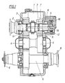
- the drive shaft 2 is mounted on top, on which two idler gears 3 are arranged.
- the idler gears 3 drive the output shaft 5 via intermediate gears 4, on which, with the aid of flanges 6, lead to two drive axles, not shown Waves are connected.
- a catch pocket 7 Arranged in the housing 1 above the drive shaft 2 is a catch pocket 7 for lubricant sprayed off by the idler gears 3.
- channel bores 8 lead to a tube 10 protruding into a longitudinal bore 9 of the drive shaft 2, the bearing points of the idler gears 3 on the drive shaft 2 being connected to the longitudinal bore 9 by transverse bores 11, thus ensuring the lubricant supply to the bearing points of the idler gears 3 .
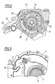
- the drive shaft 2 simultaneously drives a lubricant pump 12 designed as a gear pump, from the pressure chamber 13 of which line bores or channels 14 lead to a spray tube 15 (FIG. 4) arranged in the housing 1 parallel to the shafts, this spray tube 15 having the task of To supply tooth meshes of the gears of the transmission with lubricant.
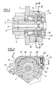
- the channel bores 8 are guided from the catch pocket 7 to the upper part of a valve chamber 16, in the lower part of which a pressure line opens from the pump pressure chamber 13 via a circumferential groove 17 in the pump housing 18 and further bores 19.
- a bore 20 extends from the central part of the valve chamber 16 to the longitudinal bore 9 in the drive shaft 2.
- a valve body designed as a ball 21 is arranged such that it can be moved up and down and closes the upper or lower part of the valve chamber 16 depending on the pump pressure. In the position shown in FIG.
Landscapes
- Engineering & Computer Science (AREA)
- General Engineering & Computer Science (AREA)
- Mechanical Engineering (AREA)
- Chemical & Material Sciences (AREA)
- Combustion & Propulsion (AREA)
- Transportation (AREA)
- General Details Of Gearings (AREA)
- Lubrication Of Internal Combustion Engines (AREA)
Claims (2)
Applications Claiming Priority (2)
| Application Number | Priority Date | Filing Date | Title |
|---|---|---|---|
| AT0120088A AT393879B (de) | 1988-05-09 | 1988-05-09 | Schmiereinrichtung fuer verteilergetriebe eines kraftfahrzeuges |
| AT1200/88 | 1988-05-09 |
Publications (3)
| Publication Number | Publication Date |
|---|---|
| EP0342183A2 EP0342183A2 (fr) | 1989-11-15 |
| EP0342183A3 EP0342183A3 (en) | 1990-06-27 |
| EP0342183B1 true EP0342183B1 (fr) | 1992-06-24 |
Family
ID=3508774
Family Applications (1)
| Application Number | Title | Priority Date | Filing Date |
|---|---|---|---|
| EP89890137A Expired - Lifetime EP0342183B1 (fr) | 1988-05-09 | 1989-05-08 | Dispositif de graissage pour la boîte à engrenage d'un véhicule à moteur |
Country Status (4)
| Country | Link |
|---|---|
| EP (1) | EP0342183B1 (fr) |
| AT (2) | AT393879B (fr) |
| DE (1) | DE58901736D1 (fr) |
| ES (1) | ES2032683T3 (fr) |
Families Citing this family (8)
| Publication number | Priority date | Publication date | Assignee | Title |
|---|---|---|---|---|
| FR2866685A1 (fr) * | 2004-02-24 | 2005-08-26 | Renault Vehicules Ind | Ensemble de mecanique adaptation |
| DE102007004964B4 (de) * | 2007-01-26 | 2012-05-16 | Sew-Eurodrive Gmbh & Co. Kg | Getriebe mit Schmierölpumpe und Getriebe-Baureihe |
| DE102007004965B4 (de) * | 2007-01-26 | 2012-05-16 | Sew-Eurodrive Gmbh & Co. Kg | Getriebe mit Ölkreislauf-Verrohrung und Getriebe-Baureihe |
| US8251675B2 (en) | 2008-04-03 | 2012-08-28 | GM Global Technology Operations LLC | Input shaft driven hybrid transmission pump |
| DE102010010804B4 (de) * | 2010-03-09 | 2025-02-27 | Sew-Eurodrive Gmbh & Co Kg | Anordnung zum Schmieren eines Getriebes und Getriebe |
| CN102392890B (zh) * | 2011-06-21 | 2014-04-16 | 三一汽车制造有限公司 | 一种变速器润滑系统及变速器 |
| DE102014212600B4 (de) | 2014-06-30 | 2019-04-25 | Danfoss Power Solutions Gmbh & Co. Ohg | Integrierte Schmierpumpe |
| JP6951997B2 (ja) * | 2018-03-23 | 2021-10-20 | 本田技研工業株式会社 | 動力伝達装置の冷却構造 |
Family Cites Families (5)
| Publication number | Priority date | Publication date | Assignee | Title |
|---|---|---|---|---|
| US2590870A (en) * | 1948-09-30 | 1952-04-01 | Timken Axle Co Detroit | Lubricating means for power transmitting mechanism |
| US3083790A (en) * | 1961-06-15 | 1963-04-02 | Int Harvester Co | Lubricating means for a power transmission |
| FR1341263A (fr) * | 1962-12-14 | 1963-10-25 | Ass Elect Ind | Perfectionnements apportés aux dispositifs de graissage des paliers de machines rotatives |
| FR1385562A (fr) * | 1963-12-03 | 1965-01-15 | Boîte à engrenages perfectionnée | |
| JPS6325421Y2 (fr) * | 1980-04-03 | 1988-07-11 |
-
1988
- 1988-05-09 AT AT0120088A patent/AT393879B/de active
-
1989
- 1989-05-08 ES ES198989890137T patent/ES2032683T3/es not_active Expired - Lifetime
- 1989-05-08 DE DE8989890137T patent/DE58901736D1/de not_active Expired - Lifetime
- 1989-05-08 AT AT89890137T patent/ATE77684T1/de not_active IP Right Cessation
- 1989-05-08 EP EP89890137A patent/EP0342183B1/fr not_active Expired - Lifetime
Also Published As
| Publication number | Publication date |
|---|---|
| DE58901736D1 (de) | 1992-07-30 |
| EP0342183A2 (fr) | 1989-11-15 |
| AT393879B (de) | 1991-12-27 |
| ATE77684T1 (de) | 1992-07-15 |
| EP0342183A3 (en) | 1990-06-27 |
| ES2032683T3 (es) | 1993-02-16 |
| ATA120088A (de) | 1991-06-15 |
Similar Documents
| Publication | Publication Date | Title |
|---|---|---|
| DE19860092C2 (de) | Getriebe mit einer Schmiervorrichtung | |
| DE3123960A1 (de) | "druckschmiervorrichtung" | |
| EP0342183B1 (fr) | Dispositif de graissage pour la boîte à engrenage d'un véhicule à moteur | |
| DE19922130C2 (de) | Schmiervorrichtung für eine Leistungsübertragungseinheit | |
| DE2904107C2 (de) | Mischtrommelantrieb für einen Transportmischer | |
| DE102015219431A1 (de) | Beölungsvorrichtung für Getriebe | |
| DE10225718A1 (de) | Zahnstangenlenkung | |
| DE1912368A1 (de) | Schmieranordnung fuer Fahrzeuglaufwerke | |
| DE3007411C2 (fr) | ||
| DE2811607A1 (de) | Gelenk-kupplung | |
| DE918007C (de) | Schmierung der Gelenkwellen-Schiebestuecke von Fahrzeugen | |
| DE1625891C2 (de) | Vorrichtung zum Niedrighalten des Wärmeanfalls bei einem Achsgetriebe für Kraftfahrzeuge | |
| DE102004043286A1 (de) | Einrichtung zur Schmierung der Lagerung des Abtriebsrades eines Portaltriebs bei einer Portalachse | |
| DE1959170A1 (de) | Antriebsaggregat fuer Fahrzeuge | |
| DE102022134016B4 (de) | Ölpumpe für Getriebe eines Elektrofahrzeugs | |
| DE1226383B (de) | Druckschmiervorrichtung fuer Planetengetriebe | |
| DE950827C (de) | Hydrostatische Kraftuebertragungseinrichtung, insbesondere fuer Kraftfahrzeuge | |
| DE307814C (fr) | ||
| AT7700U1 (de) | Differentialgetriebeeinheit mit angepasster schmierung | |
| DE390132C (de) | Schmiervorrichtung fuer Lokomotiven und aehnliche Fahrzeuge | |
| DE574775C (de) | Schmiervorrichtung fuer die am Gleiskettenfuehrungsrahmen gelagerten Kettenstuetzrollen und Kettenfuehrungsraeder von Gleiskettenfahrzeugen | |
| EP1338830A2 (fr) | Arrangement de deux ou plusieurs unités de transmission | |
| AT85628B (de) | Spurkranz-Schmiervorrichtung für Eisenbahnfahrzeuge. | |
| DE868090C (de) | Antrieb einer Welle ueber zwei Fluessigkeitsgetriebe | |
| DE102017211705A1 (de) | Schienenfahrzeuggetriebe und Schmiereinrichtung für ein Schienenfahrzeuggetriebe |
Legal Events
| Date | Code | Title | Description |
|---|---|---|---|
| PUAI | Public reference made under article 153(3) epc to a published international application that has entered the european phase |
Free format text: ORIGINAL CODE: 0009012 |
|
| AK | Designated contracting states |
Kind code of ref document: A2 Designated state(s): AT DE ES FR GB IT NL SE |
|
| PUAL | Search report despatched |
Free format text: ORIGINAL CODE: 0009013 |
|
| AK | Designated contracting states |
Kind code of ref document: A3 Designated state(s): AT DE ES FR GB IT NL SE |
|
| 17P | Request for examination filed |
Effective date: 19901024 |
|
| 17Q | First examination report despatched |
Effective date: 19911202 |
|
| GRAA | (expected) grant |
Free format text: ORIGINAL CODE: 0009210 |
|
| ITF | It: translation for a ep patent filed | ||
| AK | Designated contracting states |
Kind code of ref document: B1 Designated state(s): AT DE ES FR GB IT NL SE |
|
| REF | Corresponds to: |
Ref document number: 77684 Country of ref document: AT Date of ref document: 19920715 Kind code of ref document: T |
|
| REF | Corresponds to: |
Ref document number: 58901736 Country of ref document: DE Date of ref document: 19920730 |
|
| GBT | Gb: translation of ep patent filed (gb section 77(6)(a)/1977) | ||
| ET | Fr: translation filed | ||
| REG | Reference to a national code |
Ref country code: ES Ref legal event code: FG2A Ref document number: 2032683 Country of ref document: ES Kind code of ref document: T3 |
|
| PLBE | No opposition filed within time limit |
Free format text: ORIGINAL CODE: 0009261 |
|
| STAA | Information on the status of an ep patent application or granted ep patent |
Free format text: STATUS: NO OPPOSITION FILED WITHIN TIME LIMIT |
|
| 26N | No opposition filed | ||
| PGFP | Annual fee paid to national office [announced via postgrant information from national office to epo] |
Ref country code: GB Payment date: 19940421 Year of fee payment: 6 |
|
| PGFP | Annual fee paid to national office [announced via postgrant information from national office to epo] |
Ref country code: SE Payment date: 19940425 Year of fee payment: 6 |
|
| EAL | Se: european patent in force in sweden |
Ref document number: 89890137.6 |
|
| PG25 | Lapsed in a contracting state [announced via postgrant information from national office to epo] |
Ref country code: GB Effective date: 19950508 |
|
| PG25 | Lapsed in a contracting state [announced via postgrant information from national office to epo] |
Ref country code: SE Effective date: 19950509 |
|
| GBPC | Gb: european patent ceased through non-payment of renewal fee |
Effective date: 19950508 |
|
| EUG | Se: european patent has lapsed |
Ref document number: 89890137.6 |
|
| REG | Reference to a national code |
Ref country code: FR Ref legal event code: TP |
|
| PGFP | Annual fee paid to national office [announced via postgrant information from national office to epo] |
Ref country code: NL Payment date: 20030528 Year of fee payment: 15 |
|
| PG25 | Lapsed in a contracting state [announced via postgrant information from national office to epo] |
Ref country code: NL Free format text: LAPSE BECAUSE OF NON-PAYMENT OF DUE FEES Effective date: 20041201 |
|
| NLV4 | Nl: lapsed or anulled due to non-payment of the annual fee |
Effective date: 20041201 |
|
| PG25 | Lapsed in a contracting state [announced via postgrant information from national office to epo] |
Ref country code: IT Free format text: LAPSE BECAUSE OF NON-PAYMENT OF DUE FEES Effective date: 20050508 |
|
| PGFP | Annual fee paid to national office [announced via postgrant information from national office to epo] |
Ref country code: FR Payment date: 20050511 Year of fee payment: 17 Ref country code: AT Payment date: 20050511 Year of fee payment: 17 |
|
| PGFP | Annual fee paid to national office [announced via postgrant information from national office to epo] |
Ref country code: ES Payment date: 20050624 Year of fee payment: 17 |
|
| PG25 | Lapsed in a contracting state [announced via postgrant information from national office to epo] |
Ref country code: AT Free format text: LAPSE BECAUSE OF NON-PAYMENT OF DUE FEES Effective date: 20060508 |
|
| PG25 | Lapsed in a contracting state [announced via postgrant information from national office to epo] |
Ref country code: ES Free format text: LAPSE BECAUSE OF NON-PAYMENT OF DUE FEES Effective date: 20060509 |
|
| REG | Reference to a national code |
Ref country code: FR Ref legal event code: ST Effective date: 20070131 |
|
| REG | Reference to a national code |
Ref country code: ES Ref legal event code: FD2A Effective date: 20060509 |
|
| PG25 | Lapsed in a contracting state [announced via postgrant information from national office to epo] |
Ref country code: FR Free format text: LAPSE BECAUSE OF NON-PAYMENT OF DUE FEES Effective date: 20060531 |
|
| PGFP | Annual fee paid to national office [announced via postgrant information from national office to epo] |
Ref country code: DE Payment date: 20080515 Year of fee payment: 20 |