EP0342192B1 - Capteur optique de mesure de force - Google Patents
Capteur optique de mesure de force Download PDFInfo
- Publication number
- EP0342192B1 EP0342192B1 EP88900815A EP88900815A EP0342192B1 EP 0342192 B1 EP0342192 B1 EP 0342192B1 EP 88900815 A EP88900815 A EP 88900815A EP 88900815 A EP88900815 A EP 88900815A EP 0342192 B1 EP0342192 B1 EP 0342192B1
- Authority
- EP
- European Patent Office
- Prior art keywords
- light wave
- wave guide
- force
- measuring sensor
- layer
- Prior art date
- Legal status (The legal status is an assumption and is not a legal conclusion. Google has not performed a legal analysis and makes no representation as to the accuracy of the status listed.)
- Expired - Lifetime
Links
- 230000003287 optical effect Effects 0.000 title claims abstract description 119
- 239000000463 material Substances 0.000 claims abstract description 21
- 239000011521 glass Substances 0.000 claims description 21
- 239000013536 elastomeric material Substances 0.000 claims description 20
- 238000004519 manufacturing process Methods 0.000 claims description 18
- 239000000835 fiber Substances 0.000 claims description 11
- 238000000034 method Methods 0.000 claims description 11
- 230000008859 change Effects 0.000 claims description 5
- 238000002844 melting Methods 0.000 claims description 4
- 230000008018 melting Effects 0.000 claims description 4
- 229920001296 polysiloxane Polymers 0.000 claims description 3
- 239000000919 ceramic Substances 0.000 claims description 2
- 239000002184 metal Substances 0.000 claims description 2
- 238000000465 moulding Methods 0.000 claims 1
- 238000004804 winding Methods 0.000 claims 1
- 229920001971 elastomer Polymers 0.000 abstract 1
- 239000000806 elastomer Substances 0.000 abstract 1
- 239000013307 optical fiber Substances 0.000 description 18
- 238000005259 measurement Methods 0.000 description 9
- 230000005540 biological transmission Effects 0.000 description 8
- 230000010363 phase shift Effects 0.000 description 5
- 229910000831 Steel Inorganic materials 0.000 description 3
- 238000005266 casting Methods 0.000 description 3
- 230000006835 compression Effects 0.000 description 3
- 238000007906 compression Methods 0.000 description 3
- 239000004020 conductor Substances 0.000 description 3
- 238000005516 engineering process Methods 0.000 description 3
- 239000006060 molten glass Substances 0.000 description 3
- 239000010959 steel Substances 0.000 description 3
- 239000000126 substance Substances 0.000 description 3
- 239000000853 adhesive Substances 0.000 description 2
- 230000001070 adhesive effect Effects 0.000 description 2
- 238000009750 centrifugal casting Methods 0.000 description 2
- 238000013461 design Methods 0.000 description 2
- 238000011161 development Methods 0.000 description 2
- 230000018109 developmental process Effects 0.000 description 2
- 239000013013 elastic material Substances 0.000 description 2
- 239000004744 fabric Substances 0.000 description 2
- 239000005357 flat glass Substances 0.000 description 2
- 238000000691 measurement method Methods 0.000 description 2
- 229920001084 poly(chloroprene) Polymers 0.000 description 2
- 230000001681 protective effect Effects 0.000 description 2
- 238000003466 welding Methods 0.000 description 2
- 230000009471 action Effects 0.000 description 1
- 238000004026 adhesive bonding Methods 0.000 description 1
- 230000015572 biosynthetic process Effects 0.000 description 1
- 230000008878 coupling Effects 0.000 description 1
- 238000010168 coupling process Methods 0.000 description 1
- 238000005859 coupling reaction Methods 0.000 description 1
- 230000001419 dependent effect Effects 0.000 description 1
- 238000009713 electroplating Methods 0.000 description 1
- 230000008030 elimination Effects 0.000 description 1
- 238000003379 elimination reaction Methods 0.000 description 1
- 238000011156 evaluation Methods 0.000 description 1
- 239000003365 glass fiber Substances 0.000 description 1
- 239000011796 hollow space material Substances 0.000 description 1
- 238000009533 lab test Methods 0.000 description 1
- 238000010309 melting process Methods 0.000 description 1
- 239000012528 membrane Substances 0.000 description 1
- 238000012986 modification Methods 0.000 description 1
- 230000004048 modification Effects 0.000 description 1
- 229920003023 plastic Polymers 0.000 description 1
- 239000004033 plastic Substances 0.000 description 1
- 239000002986 polymer concrete Substances 0.000 description 1
- 229920002635 polyurethane Polymers 0.000 description 1
- 239000004814 polyurethane Substances 0.000 description 1
- 238000011112 process operation Methods 0.000 description 1
- 238000012545 processing Methods 0.000 description 1
- 230000001902 propagating effect Effects 0.000 description 1
- 239000011347 resin Substances 0.000 description 1
- 229920005989 resin Polymers 0.000 description 1
- 230000008054 signal transmission Effects 0.000 description 1
- 229920002379 silicone rubber Polymers 0.000 description 1
- 239000004945 silicone rubber Substances 0.000 description 1
- 125000006850 spacer group Chemical group 0.000 description 1
- 239000012209 synthetic fiber Substances 0.000 description 1
- 229920002994 synthetic fiber Polymers 0.000 description 1
- 238000012360 testing method Methods 0.000 description 1
- 210000002105 tongue Anatomy 0.000 description 1
- 238000009827 uniform distribution Methods 0.000 description 1
- 238000009941 weaving Methods 0.000 description 1
Images
Classifications
-
- G—PHYSICS
- G01—MEASURING; TESTING
- G01L—MEASURING FORCE, STRESS, TORQUE, WORK, MECHANICAL POWER, MECHANICAL EFFICIENCY, OR FLUID PRESSURE
- G01L1/00—Measuring force or stress, in general
- G01L1/24—Measuring force or stress, in general by measuring variations of optical properties of material when it is stressed, e.g. by photoelastic stress analysis using infrared, visible light, ultraviolet
- G01L1/242—Measuring force or stress, in general by measuring variations of optical properties of material when it is stressed, e.g. by photoelastic stress analysis using infrared, visible light, ultraviolet the material being an optical fibre
- G01L1/243—Measuring force or stress, in general by measuring variations of optical properties of material when it is stressed, e.g. by photoelastic stress analysis using infrared, visible light, ultraviolet the material being an optical fibre using means for applying force perpendicular to the fibre axis
-
- G—PHYSICS
- G01—MEASURING; TESTING
- G01D—MEASURING NOT SPECIALLY ADAPTED FOR A SPECIFIC VARIABLE; ARRANGEMENTS FOR MEASURING TWO OR MORE VARIABLES NOT COVERED IN A SINGLE OTHER SUBCLASS; TARIFF METERING APPARATUS; MEASURING OR TESTING NOT OTHERWISE PROVIDED FOR
- G01D5/00—Mechanical means for transferring the output of a sensing member; Means for converting the output of a sensing member to another variable where the form or nature of the sensing member does not constrain the means for converting; Transducers not specially adapted for a specific variable
- G01D5/26—Mechanical means for transferring the output of a sensing member; Means for converting the output of a sensing member to another variable where the form or nature of the sensing member does not constrain the means for converting; Transducers not specially adapted for a specific variable characterised by optical transfer means, i.e. using infrared, visible, or ultraviolet light
- G01D5/32—Mechanical means for transferring the output of a sensing member; Means for converting the output of a sensing member to another variable where the form or nature of the sensing member does not constrain the means for converting; Transducers not specially adapted for a specific variable characterised by optical transfer means, i.e. using infrared, visible, or ultraviolet light with attenuation or whole or partial obturation of beams of light
- G01D5/34—Mechanical means for transferring the output of a sensing member; Means for converting the output of a sensing member to another variable where the form or nature of the sensing member does not constrain the means for converting; Transducers not specially adapted for a specific variable characterised by optical transfer means, i.e. using infrared, visible, or ultraviolet light with attenuation or whole or partial obturation of beams of light the beams of light being detected by photocells
- G01D5/353—Mechanical means for transferring the output of a sensing member; Means for converting the output of a sensing member to another variable where the form or nature of the sensing member does not constrain the means for converting; Transducers not specially adapted for a specific variable characterised by optical transfer means, i.e. using infrared, visible, or ultraviolet light with attenuation or whole or partial obturation of beams of light the beams of light being detected by photocells influencing the transmission properties of an optical fibre
- G01D5/35303—Mechanical means for transferring the output of a sensing member; Means for converting the output of a sensing member to another variable where the form or nature of the sensing member does not constrain the means for converting; Transducers not specially adapted for a specific variable characterised by optical transfer means, i.e. using infrared, visible, or ultraviolet light with attenuation or whole or partial obturation of beams of light the beams of light being detected by photocells influencing the transmission properties of an optical fibre using a reference fibre, e.g. interferometric devices
Definitions
- the invention relates to a force measuring sensor with a fibrous optical waveguide, which is embedded in a layer of pressure or force-transmitting material and changes its light transmission properties under the influence of a force or a pressure, these changes being used to measure the force or pressure, and an associated manufacturing method .
- Such a force measuring sensor is known from WO-A-86 05 273, the optical waveguide being embedded in an elastomeric material, in particular silicone or polyurethane, and thereby being fastened to an elastically deformable measuring body, in particular measuring tongues.
- covers of the optical waveguide are described by elastic material such as neoprene or synthetic and natural fibers. Due to this elastic introduction of force or transmission of force to the optical waveguide by embedding it in elastic material, the force to be measured cannot be measured proportionally, so that there is considerable inaccuracy in the measurement.
- the force sensors described are sensitive to mechanical or chemical influences despite additional elastic protective films made of neoprene or glued-on synthetic fibers. Due to the embedding in silicone in a first manufacturing step and the additional gluing of protective films, the adhesive strength of the individual parts suffers from one another and necessitates a large number of manufacturing steps which make the manufacturing process correspondingly more expensive.
- a multilayer transmission element is also known, wherein a core fiber is wrapped by several sheath fibers.
- This transmission element is used for signal transmission over several kilometers and is neither designed nor suitable as a force measuring sensor.
- the invention has for its object to provide a fiber optic force measuring sensor that is relatively insensitive to external influences with high measuring accuracy and can be manufactured extremely easily, and to specify a manufacturing method for this.
- the force measuring sensor according to the invention has the features of patent claims 1 and 2, and as an optical waveguide combination the features of patent claim 14.
- the methods according to the invention for producing such a force measuring sensor are specified in patent claims 15, 18 and 20.
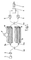
- FIG. 1 shows, for example, the principle of an optical sensor according to the invention, which works as a so-called Mach-Zehnder sensor.
- a monochromatic light source 1 for example a laser diode
- light is applied via a polarizer 2 to a coupler 4a, which divides the light into a measuring light waveguide 3a and a reference light waveguide 3b.
- the light emerging from the two optical waveguides 3a, 3b is applied to a further coupler 4b, detected in photoelectric elements 5, the electrical output signals of which are processed in a processor 6 to an output value which is displayed in a display 7.
- the principle described so far is known, as is the embedding of the measuring light waveguide 3a in a force-transmitting material 10, preferably elastomeric material, which essentially completely transmits a force F to the measuring light waveguide 3a.
- the reference optical waveguide 3b is arranged free from the influence of the force F. It can be guided in a cavity 12 of the material 10; alternatively, there is also the possibility of attaching the reference optical waveguide 3b for temperature compensation outside of the elastomeric material 10 in the vicinity thereof.
- the measuring principle shown in FIG. 1 is that of a two-beam interferometer, the Mach-Zehnder interferometer using the phase shift caused by the force F in the measuring optical waveguide 3a with respect to the light in the reference optical waveguide 3b for the measurement.
- the refractive index n changes with all-sided pressure of the elastomeric material 10 on the measuring optical waveguide 3a, which leads to a corresponding phase shift.
- Another change in the light transmission properties of the measurement optical waveguide 3a would be a change in length due to the force F or a deflection.
- the principle of the Mach-Zehnder double-beam interferometer shown in FIG. 1 is only one example of the use of a single-wave optical waveguide. Other possibilities are described in the publications mentioned, including the use of multi-wave optical fibers.
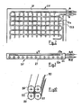
- FIG. 2 shows a practical exemplary embodiment of an optical sensor 20 according to the invention, which preferably has a flat design, that is to say in which the height or thickness is substantially less than the length and width dimensions.
- the sensor 20 consists of a layer of force-transmitting material, preferably elastomeric material, in which a measuring light waveguide 13a is embedded in a meandering shape as the upper layer 23.
- a measuring light waveguide 13a is embedded in a meandering shape as the upper layer 23.
- the reference optical waveguide 13b in tubes 22 is then likewise guided in the layer 21 in a meandering manner.
- the reference light waveguide 13b is thus arranged free of forces.
- Optical waveguide cables 14, 16 connect the measuring optical waveguide 13a to the couplers 4a and 4b of FIG. 1. In the same way, the reference optical waveguide 13b is connected to the couplers 4a, 4b via optical waveguide cables 18, 19.
- the measuring optical waveguide 13a has a considerable length due to the meandering guide, which can be between fractions of a meter and a few km.
- the reference light waveguide 13b preferably, but not necessarily, has the same length as the measuring waveguide 13a.
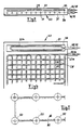
- FIGS. 4 and 5 show a further embodiment of an optical sensor 30 according to the invention, in which a layer 21 of elastomeric material is arranged between two steel plates 32, 34, so that there is a uniform distribution of a force F acting on the upper steel plate 32 in the Layer 31 results.
- the reference light guide 23b is arranged in a larger cavity 36 separately from the measurement light waveguide 23a to the side thereof. Furthermore, the measuring light waveguide 23a was placed in two superimposed layers 24 and 26 arranged in a meandering manner, whereby a further extension of the measuring light waveguide 23a is possible. The distance between the two layers can be chosen so that no light coupling occurs between them.
- one of the layers 24, 26 could also be led out separately and only one have such a distance from the other layer that, when force is applied, light is decoupled from the actual measuring light waveguide layer into the other layer, which can then be used to localize the force on layer 21.
- the upper steel plate 32 would preferably be omitted.
- a corresponding connection to the couplers 4a and 4b takes place via optical fiber cables 44, 46, 48, 49.
- the measuring optical waveguide and the reference optical waveguide are not of the same length, this must of course be taken into account accordingly in the electronic evaluation in the processor 6.
- the reference optical waveguide is guided in or in the vicinity of the elastomeric layer, for example in the pressure-free chamber 36 or in the openings 26 formed, for example, by tubes, temperature changes are effectively compensated for.
- the force-transmitting material in which the optical waveguides are embedded is an elastomeric material, which should preferably be produced without bubbles. This can be achieved either by curing the elastomeric material in a vacuum or by centrifugal casting, as will be explained in more detail below.
- a material of substantially greater hardness can also take the place of the elastomeric material if it passes on the forces or pressures exerted on the layer completely or at least uniformly.
- Glass could also be considered as such a material, the optical waveguides, which are preferably made of glass, being embedded in a molten glass frit which has a lower melting point than the optical waveguides.
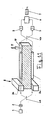
- 6 to 8 show a further embodiment of the optical sensor according to the invention applied to a load cell, as described for example in WO-A-86 03 584.
- a piston 54 is guided inside a pot-shaped housing 52 to form a narrow annular gap 55.
- a space 56 between the underside of the piston 54 and the bottom of the housing 52 is filled with an elastomeric material, in which a measuring optical waveguide 58 is embedded, which is connected to the couplers 4a, 4b (FIG. 1) via optical fiber cables 66, 67 .
- a reference light waveguide 62 is accommodated independently of the measurement light waveguide 58, for example in an opening 60 formed on the underside of the housing 52, which can be closed by means of a cover plate 64.
- the reference optical waveguide 62 is in turn connected to the couplers 4a and 4b via optical fiber cables 68, 69.
- the measuring light waveguide 58 and preferably also the reference light waveguide 62 can have a considerable length between fractions of a meter and a few hundred meters.
- the optical waveguides can in turn be meandering in one or more layers.
- An alternative form would be a spiral, bifilar formation with a bent inner end.
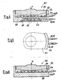
- FIG. 8 shows an embodiment of an optical sensor 70 modified from the embodiment according to FIG. 6, in which the reference optical waveguide is omitted. This is possible when temperature compensation is not required and a pulse method, for example in a multi-wave optical fiber, is used for the measurement.
- FIG. 7 shows the top view of the embodiments according to FIGS. 6 and 8, to explain the routing of the optical fiber cables 66, 67, 68, 69.
- the elastomeric material used in the various exemplary embodiments can preferably be silicone rubber. Further usable substances are specified in the mentioned WO-A-86 03 584.
- the methods explained in this publication can be used in the production of the sensors according to the invention, the curing of the elastomeric material either taking place in a vacuum or using centrifugal casting. In this way, bubble-free elastomeric material can be produced which completely transmits forces or pressures to the measuring light waveguide 58.
- FIG. 9 shows a series connection of a plurality of spaced-apart force measuring cells with an optical sensor according to FIGS. 6 to 8, the optical waveguides being connected in series by optical fiber cables 80 and 82, respectively. The beginning and end are again connected to the couplers 4a, 4b (Fig. 1). In this way, an extensive force measuring carpet can be produced.
- FIG. 10 shows an optical waveguide structure according to which at least three, in the exemplary embodiment four optical waveguides 90 are melted together running parallel to one another.
- the reference optical waveguide 92 can then be arranged in the hollow space resulting in the middle.
- Such a light guide combination can then be embedded in the elastomeric layer instead of the measuring light waveguide in a meandering or spiral shape or the like.
- the measuring light waveguides 90 are then connected in series with one another and there is an exact length relationship between the measuring light waveguides 90 and the reference light waveguide 92.
- the outer measuring optical waveguides 90 are loaded by pressure, which leads to elastic tensions in the longitudinal and transverse directions in the measuring optical waveguides 90, as a result of which the refractive index changes in these light source conductors.
- the reference waveguide 92 is not affected by the pressure changes.
- optical sensors with single-wave light guides have been described in connection with FIG. 1, any other optical wave guides such as side-hole fibers, wire-wound fibers, twisted fibers with pressure-relieved reference fiber can be used.
- the optical measuring principle is also not limited to a Mach-Zehnder two-beam interferometer.
- a preferably cut-to-length optical waveguide section can also be arranged in the above-described optical sensors for the adjustment between measuring optical waveguide and reference optical waveguide, which section is connected in series to one or the other optical waveguide, for example for zero compensation.
- the optical waveguides can be embedded in a simple manner in the form of a fabric in the elastomeric material, for example using methods as are known in the production of conveyor belts or the like.
- the optical waveguide packages can also be applied to a sheet-like base, which is then embedded in the elastomeric material.
- the meandering can be achieved, for example, by means of weaving technology, which means that, for example, weft and warp are used.
- FIGS. 11 to 13 show a modification of the interferometer according to FIG. 1.
- the measuring light waveguide 3a is attached to an elastically deformable body 10 which is clamped on one side in a holder 8.
- the measuring optical waveguide 3a is arranged on the upper side of the body 10, while the reference optical waveguide 3b is located on the lower side thereof. This differs from the arrangement known per se, in which the reference optical waveguide 3b is unaffected by the force F acting on the body 10.
- this force F Under the action of this force F, the body 10 bends, as a result of which the measuring light waveguide 3a is stretched and the reference light waveguide 3b is compressed. This results in a phase shift between the light components that run through the two optical fibers 3a, 3b. This phase shift is determined in the devices 5, 6. A corresponding force value is calculated from the phase shift and displayed on the display 7.
- the reference optical waveguide 3b can also be arranged unaffected by the force F, that is, separately from the body 10.
- the solution shown in FIG. 11 offers the possibility of evaluating the expansion or compression of the optical waveguides 3a and 3b separately and, similarly to the conventional resistance measurement method, of making a difference.
- the reference optical waveguide 3b can also be omitted if temperature compensation is not required or is carried out electronically in the processor 6. In this case, the light transmission takes place by means of a time measurement method, in which the transit time of light pulses is determined by the measurement light waveguide 3a.
- optical waveguide section 11 shows only a straight optical waveguide section for the measurement and reference optical waveguides 3a, 3b. According to the invention, however, optical fibers of considerable length are used, which can range from fractions of a meter to a few kilometers.
- the body 10 can be a metal spring in conventional strain gauge devices or consist of glass, ceramic, non-creeping plastic or polymer concrete. It is essential for the invention to attach the optical waveguides 3a, 3b to the body 10. This is done by embedding the optical waveguides in a glass mass or frit, the melting point of which is lower than that of the optical waveguides 3a, 3b.
- the optical fiber (s) 3a, 3b are embedded in a correspondingly meandering manner in the direction of tension or extension, in the case of linear stress, if necessary in a bifilar spiral, in a molten glass mass or frit which is applied to the body 10 or . becomes.
- the optical waveguides can be in the manner of a fabric or can be applied to a glass frame. Alternatively, the optical waveguides can be applied to the surface of the body 10 and fused there by means of glass. It would also be possible to apply the optical waveguides to a sheet-like base, which preferably consists of a material that volatilizes during the melting process.
- the production can either take place in a process operation in which the optical waveguides are arranged on the body 10, for example from a glass frame, and are then embedded with molten glass mass. Of course, this has a lower melting point than the optical fibers.
- the production can also take place in layers, namely by applying a first glass layer on the body 10, arranging the optical waveguides on the glass layer and covering the optical waveguides by means of a second glass mass layer.
- a production method in which the body 10 is cast from the non-creeping material, preferably glass, is particularly advantageous, in which case the light guide threads are arranged, for example on a glass frame in the casting mold for the body 10, and are already cast in during the casting process, so that an integrated one is integrated Unity results.
- glass was predominantly given as the investment material.
- other materials can also be used, provided that they do not "creep" under load. An example of this would be a two-component casting resin.
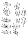
- the optical force measuring sensor according to the invention can be designed in the same way as known strain gauge load cells.
- FIG. 12a shows a stamp force generator 120 of, for example, a cylindrical design, in which the one optical waveguide 3a is preferably wound many times around the circumference, while the optical waveguide 3b is applied to the body in a meandering manner in the compression direction, for example.
- FIG. 12b shows a similar stamp force generator 122 in the form of a hollow shaft with a wound light guide 3a and two light waveguides 3b attached on opposite sides of the body in the compression direction, which are preferably connected in series.
- FIG. 12c shows a torsion ring 124 with, for example, a square cross section standing on the tip, the optical waveguide 3a being arranged in the region of the upper ring edge and the optical waveguide 3b being arranged in the region of the lower ring edge.
- FIGS. 12d and 12e again show punch force transmitters 126 and 128, in which case pairs of light conductors 3a and 3b are applied in a pulling or compressing direction in a cylindrical opening running perpendicular to the direction of force application.
- FIG. 12f illustrates a bar-shaped body 130 clamped on one side with a cylindrical opening, in which, as in the exemplary embodiment in FIG. 2d, optical fiber pairs 3a and 3b are arranged.
- 12g schematically represents a bar-shaped shear force generator 132, in which optical waveguides 13a and 13b are arranged in a horizontally widened opening at an angle of 45 ° with respect to the direction of force introduction and offset meanderingly at right angles to one another.
- 12h shows a bar-shaped transmitter in the manner of a double link, in which two cylindrical openings are provided horizontally next to one another in the bar 134.
- the optical fibers 3a and 3b are arranged in pairs opposite each other on the top and bottom of the beam 134 at the thinnest points.
- only the measuring light waveguide 3a is preferably applied in a meandering manner in the pulling or compressing direction on the upper (or lower side) of the bar, while a reference light waveguide 23b is arranged on the back of the bar without the influence of force.
- 12k finally shows a bar-shaped strain gauge transducer 138 with the optical waveguides 3a and 3b, preferably meandering, arranged on the top and bottom.
- the optical waveguides can be applied and embedded in accordance with the method according to the invention.
- FIG. 13a and 13b show two different embodiments of optical force sensors according to the invention.
- a stamp force generator 140 is cut horizontally and provided with an intermediate layer in which the optical waveguide 3a is embedded.
- a bifilar spiral arrangement could preferably be selected in this embodiment, which consists of a single optical waveguide that is bent in the middle.
- the optical waveguides are in turn embedded in glass or, in this case, in a bubble-free elastomeric material that transmits the force exerted on the stamp completely to the optical waveguide (s) 3a.
- FIG. 13b shows a similarly functioning embodiment in which the optical waveguide 3a is arranged between two panes, for example washers 142, 144. With such an arrangement, the tightening of screws to a desired pressure could be determined.
- a combined optical waveguide according to FIG. 10 could also be used for the exemplary embodiments in FIGS. 13a and 13b.
- a preferably cut-to-length optical waveguide section can also be arranged in the above-described optical sensors for the adjustment between measuring optical waveguide and reference optical waveguide, which section is connected in series to one or the other optical waveguide, for example for zero compensation.
- optical waveguide arrangement or packages can be connected in series in a simple manner by means of optical fiber cables or continuation of the optical waveguide.
- several sensors arranged at a distance from one another can be optically connected in series with one another.
- the body 10 is formed, for example, as a membrane, on the surfaces of which the optical waveguides are applied in the manner according to the invention.
Landscapes
- Physics & Mathematics (AREA)
- General Physics & Mathematics (AREA)
- Measuring Fluid Pressure (AREA)
- Light Guides In General And Applications Therefor (AREA)
- Optical Transform (AREA)
- Force Measurement Appropriate To Specific Purposes (AREA)
- Optical Integrated Circuits (AREA)
Abstract
Claims (20)
Priority Applications (1)
| Application Number | Priority Date | Filing Date | Title |
|---|---|---|---|
| AT88900815T ATE58435T1 (de) | 1987-01-21 | 1988-01-20 | Optischer kraftmess-sensor. |
Applications Claiming Priority (4)
| Application Number | Priority Date | Filing Date | Title |
|---|---|---|---|
| DE3701548 | 1987-01-21 | ||
| DE3701632 | 1987-01-21 | ||
| DE19873701632 DE3701632A1 (de) | 1987-01-21 | 1987-01-21 | Optischer sensor |
| DE19873701548 DE3701548A1 (de) | 1987-01-21 | 1987-01-21 | Optischer kraftmessensor |
Publications (2)
| Publication Number | Publication Date |
|---|---|
| EP0342192A1 EP0342192A1 (fr) | 1989-11-23 |
| EP0342192B1 true EP0342192B1 (fr) | 1990-11-14 |
Family
ID=25851708
Family Applications (1)
| Application Number | Title | Priority Date | Filing Date |
|---|---|---|---|
| EP88900815A Expired - Lifetime EP0342192B1 (fr) | 1987-01-21 | 1988-01-20 | Capteur optique de mesure de force |
Country Status (6)
| Country | Link |
|---|---|
| US (1) | US5012679A (fr) |
| EP (1) | EP0342192B1 (fr) |
| JP (1) | JPH02501947A (fr) |
| KR (1) | KR890700814A (fr) |
| DE (1) | DE3861095D1 (fr) |
| WO (1) | WO1988005529A1 (fr) |
Cited By (1)
| Publication number | Priority date | Publication date | Assignee | Title |
|---|---|---|---|---|
| EP3553249A4 (fr) * | 2016-12-01 | 2020-09-02 | Boe Technology Group Co. Ltd. | Unité de plancher, plancher et système domestique basé sur l'internet des objets |
Families Citing this family (21)
| Publication number | Priority date | Publication date | Assignee | Title |
|---|---|---|---|---|
| GB2208711A (en) * | 1988-08-16 | 1989-04-12 | Plessey Co Plc | Fibre optic sensor |
| GB2250813A (en) * | 1990-12-15 | 1992-06-17 | British Aerospace | Weighing apparatus for vehicles |
| FR2680188B1 (fr) * | 1991-08-06 | 1998-09-04 | Freyssinet Int & Co | Perfectionnements aux plots d'appui elastiquement deformables et aux ouvrages equipes de tels plots. |
| EP0608645A1 (fr) * | 1993-01-29 | 1994-08-03 | FREYSSINET INTERNATIONAL et COMPAGNIE | Perfectionnements aux dispositifs d'appui pour charges lourdes et aux ouvrages équipés de tels dispositifs |
| US5446546A (en) * | 1993-07-02 | 1995-08-29 | The Boeing Company | Laser interferometric single piece force transducer |
| US5396805A (en) * | 1993-09-30 | 1995-03-14 | Halliburton Company | Force sensor and sensing method using crystal rods and light signals |
| AUPM547194A0 (en) * | 1994-05-06 | 1994-06-02 | University Of Sydney, The | Variable property light transmitting device |
| DE4428650A1 (de) * | 1994-08-12 | 1996-02-15 | Marinitsch Waldemar | Optische Druckkrafterfassungsvorrichtung |
| AUPR357801A0 (en) * | 2001-03-07 | 2001-04-05 | Future Fibre Technologies Pty Ltd | Perimeter security system and perimeter monitoring method |
| FR2836548A1 (fr) * | 2002-02-22 | 2003-08-29 | Air Liquide | Structure composite comprenant des moyens de detection de phenomenes physique, et utilisation d'une fibre de materiau composite pour realiser une telle detection |
| US20070037462A1 (en) * | 2005-05-27 | 2007-02-15 | Philbrick Allen | Optical fiber substrate useful as a sensor or illumination device component |
| CA2601836C (fr) * | 2007-05-21 | 2017-02-28 | Adam Densmore | Biocapteur de guide d'onde photonique en silicium |
| EP2034287A1 (fr) * | 2007-09-10 | 2009-03-11 | Nederlandse Organisatie voor Toegepast-Natuuurwetenschappelijk Onderzoek TNO | Capteur optique pour mesurer une distribution de force |
| US8456635B2 (en) * | 2008-10-24 | 2013-06-04 | University Of Notre Dame Du Lac | Methods and apparatus to obtain suspended particle information |
| DE102009006531A1 (de) * | 2009-01-28 | 2010-07-29 | P+W Metallbau Gmbh & Co. Kg | Vorrichtung zur Gewichtsbestimmung des Siloinhaltes eines Silos |
| GB0909512D0 (en) * | 2009-06-03 | 2009-07-15 | Airbus Uk Ltd | Weight measurement apparatus and method |
| US20130088710A1 (en) * | 2011-10-07 | 2013-04-11 | Francois Jean Michel Bergeron | Optical Guide-Based Displacement/Force Sensor |
| DE102012019407A1 (de) * | 2012-10-04 | 2014-04-10 | Leoni Kabel Holding Gmbh | Optische Sensoranordnung sowie Verfahren zur Erfassung einer Messgröße mit Hilfe einer optischen Sensoranordnung |
| US9470512B2 (en) * | 2014-07-22 | 2016-10-18 | Avago Technologies General Ip (Singapore) Pte. Ltd. | Pre-formed optical meander structures for use in an optical strain gauge system for measuing strain, and a method |
| DE102014014252A1 (de) * | 2014-09-26 | 2016-03-31 | P+W Metallbau Gmbh & Co. Kg | Vorrichtung zur Gewichtserfassung von Behältern, insbesondere Silos |
| WO2019066800A1 (fr) * | 2017-09-27 | 2019-04-04 | Sikorsky Aircraft Corporation | Utilisation de capteurs de contrainte à fibre optique pour surveiller des dommages de fixation dans des structures |
Family Cites Families (6)
| Publication number | Priority date | Publication date | Assignee | Title |
|---|---|---|---|---|
| DE2521659A1 (de) * | 1975-05-13 | 1976-12-02 | Siemens Ag | Optisches uebertragungselement und verfahren zu seiner herstellung |
| US4659923A (en) * | 1981-03-09 | 1987-04-21 | Polaroid Corporation | Fiber optic interferometer transducer |
| US4560016A (en) * | 1983-12-14 | 1985-12-24 | Anco Engineers, Incorporated | Method and apparatus for measuring the weight of a vehicle while the vehicle is in motion |
| FR2578645B1 (fr) * | 1985-03-07 | 1987-03-20 | Sopha Praxis | Dispositif optique de detection d'effort, procede de mesure d'effort au moyen dudit dispositif et leur application a une balance |
| US4671659A (en) * | 1985-11-08 | 1987-06-09 | Martin Marietta Corporation | Fiber optic displacement sensor |
| US4814562A (en) * | 1987-11-13 | 1989-03-21 | University Of Arkansas | Electro-optic force and pressure transducer and sensor |
-
1988
- 1988-01-02 KR KR1019880701136A patent/KR890700814A/ko not_active Withdrawn
- 1988-01-20 DE DE8888900815T patent/DE3861095D1/de not_active Expired - Fee Related
- 1988-01-20 EP EP88900815A patent/EP0342192B1/fr not_active Expired - Lifetime
- 1988-01-20 US US07/392,623 patent/US5012679A/en not_active Expired - Fee Related
- 1988-01-20 JP JP63500993A patent/JPH02501947A/ja active Pending
- 1988-01-20 WO PCT/DE1988/000026 patent/WO1988005529A1/fr not_active Ceased
Non-Patent Citations (1)
| Title |
|---|
| First International Conference on Optical Fibre Sensors, 26.-28. April 1983, S.C. Raleigh: "Polarimetric sensors: exploiting the axial stress in high birefringence fibers", Seiten 210-213 * |
Cited By (1)
| Publication number | Priority date | Publication date | Assignee | Title |
|---|---|---|---|---|
| EP3553249A4 (fr) * | 2016-12-01 | 2020-09-02 | Boe Technology Group Co. Ltd. | Unité de plancher, plancher et système domestique basé sur l'internet des objets |
Also Published As
| Publication number | Publication date |
|---|---|
| US5012679A (en) | 1991-05-07 |
| JPH02501947A (ja) | 1990-06-28 |
| KR890700814A (ko) | 1989-04-27 |
| DE3861095D1 (de) | 1990-12-20 |
| EP0342192A1 (fr) | 1989-11-23 |
| WO1988005529A1 (fr) | 1988-07-28 |
Similar Documents
| Publication | Publication Date | Title |
|---|---|---|
| EP0342192B1 (fr) | Capteur optique de mesure de force | |
| DE69912301T2 (de) | Sensor zur messung mechanischer spannungen mit fiber-optischen bragg gittern | |
| EP0340577B1 (fr) | Procédé et dispositif pour la détermination de l'indice de réfractions d'une substance | |
| EP1899700B1 (fr) | Jauge extensometrique optique | |
| EP2126511B1 (fr) | Jauge optique d'allongement | |
| DE69203834T2 (de) | Eigenschaden-Kontrollvorrichtung und Verfahren zur Herstellung und Anwendung. | |
| DE112014004544B4 (de) | FBG-Sensor zur Messung maximaler Dehnung, Herstellungsverfahren und Verwendungsverfahren | |
| DE3432989C2 (fr) | ||
| DE19724528B4 (de) | Temperaturkompensiertes faseroptisches Bragg-Gitter | |
| DE102013101432B4 (de) | Faseroptischer Beschleunigungssensor mit Hebel | |
| DE102011050717B4 (de) | Messsystem und Verfahren zum Validieren eines faseroptischen Sensor | |
| EP0445362B1 (fr) | Dispositif de mesure d'une induction magnétique | |
| EP0361588A1 (fr) | Capteur à fibre optique | |
| DE3621669A1 (de) | Optischer drucksensor | |
| DE102011084579A1 (de) | Vorrichtung und Verfahren zur Überwachung des Zustands einer Klebverbindung | |
| DE3608599C2 (fr) | ||
| DE3701632A1 (de) | Optischer sensor | |
| DE2521319B2 (de) | Piezooptischer Meßwandler | |
| WO2018141501A1 (fr) | Dispositif de détection à fibre optique et procédé pour faire fonctionner un dispositif de détection à fibre optique | |
| WO2007000324A2 (fr) | Jauge extensometrique optique | |
| DE3701548A1 (de) | Optischer kraftmessensor | |
| EP2294374B1 (fr) | Capteur optique d allongement | |
| DE69637401T2 (de) | Optischer Spannungsfühler, Gruppe optischer Teile und Herstellungsverfahren dazu | |
| DE3129847A1 (de) | "verfahren und anordnung zur messung mechanischer groessen" | |
| WO2002088013A1 (fr) | Dispositif destine a mesurer la tension d'un fil sur la base d'un principe de mesure photoelastique |
Legal Events
| Date | Code | Title | Description |
|---|---|---|---|
| PUAI | Public reference made under article 153(3) epc to a published international application that has entered the european phase |
Free format text: ORIGINAL CODE: 0009012 |
|
| 17P | Request for examination filed |
Effective date: 19890714 |
|
| AK | Designated contracting states |
Kind code of ref document: A1 Designated state(s): AT BE CH DE FR GB IT LI NL |
|
| 17Q | First examination report despatched |
Effective date: 19900430 |
|
| GRAA | (expected) grant |
Free format text: ORIGINAL CODE: 0009210 |
|
| AK | Designated contracting states |
Kind code of ref document: B1 Designated state(s): AT BE CH DE FR GB IT LI NL |
|
| REF | Corresponds to: |
Ref document number: 58435 Country of ref document: AT Date of ref document: 19901115 Kind code of ref document: T |
|
| REF | Corresponds to: |
Ref document number: 3861095 Country of ref document: DE Date of ref document: 19901220 |
|
| ITF | It: translation for a ep patent filed | ||
| ITTA | It: last paid annual fee | ||
| PGFP | Annual fee paid to national office [announced via postgrant information from national office to epo] |
Ref country code: NL Payment date: 19910131 Year of fee payment: 4 |
|
| ET | Fr: translation filed | ||
| GBT | Gb: translation of ep patent filed (gb section 77(6)(a)/1977) | ||
| PLBE | No opposition filed within time limit |
Free format text: ORIGINAL CODE: 0009261 |
|
| STAA | Information on the status of an ep patent application or granted ep patent |
Free format text: STATUS: NO OPPOSITION FILED WITHIN TIME LIMIT |
|
| 26N | No opposition filed | ||
| PGFP | Annual fee paid to national office [announced via postgrant information from national office to epo] |
Ref country code: GB Payment date: 19920117 Year of fee payment: 5 |
|
| PGFP | Annual fee paid to national office [announced via postgrant information from national office to epo] |
Ref country code: CH Payment date: 19920120 Year of fee payment: 5 |
|
| PGFP | Annual fee paid to national office [announced via postgrant information from national office to epo] |
Ref country code: BE Payment date: 19920121 Year of fee payment: 5 Ref country code: AT Payment date: 19920121 Year of fee payment: 5 |
|
| PG25 | Lapsed in a contracting state [announced via postgrant information from national office to epo] |
Ref country code: NL Effective date: 19920801 |
|
| NLV4 | Nl: lapsed or anulled due to non-payment of the annual fee | ||
| PG25 | Lapsed in a contracting state [announced via postgrant information from national office to epo] |
Ref country code: GB Effective date: 19930120 Ref country code: AT Effective date: 19930120 |
|
| PG25 | Lapsed in a contracting state [announced via postgrant information from national office to epo] |
Ref country code: LI Effective date: 19930131 Ref country code: CH Effective date: 19930131 Ref country code: BE Effective date: 19930131 |
|
| BERE | Be: lapsed |
Owner name: PFISTER G.M.B.H. Effective date: 19930131 |
|
| GBPC | Gb: european patent ceased through non-payment of renewal fee |
Effective date: 19930120 |
|
| REG | Reference to a national code |
Ref country code: CH Ref legal event code: PL |
|
| PGFP | Annual fee paid to national office [announced via postgrant information from national office to epo] |
Ref country code: FR Payment date: 19951222 Year of fee payment: 9 |
|
| PGFP | Annual fee paid to national office [announced via postgrant information from national office to epo] |
Ref country code: DE Payment date: 19960131 Year of fee payment: 9 |
|
| PG25 | Lapsed in a contracting state [announced via postgrant information from national office to epo] |
Ref country code: FR Effective date: 19970930 |
|
| PG25 | Lapsed in a contracting state [announced via postgrant information from national office to epo] |
Ref country code: DE Effective date: 19971001 |
|
| REG | Reference to a national code |
Ref country code: FR Ref legal event code: ST |
|
| PG25 | Lapsed in a contracting state [announced via postgrant information from national office to epo] |
Ref country code: IT Free format text: LAPSE BECAUSE OF NON-PAYMENT OF DUE FEES;WARNING: LAPSES OF ITALIAN PATENTS WITH EFFECTIVE DATE BEFORE 2007 MAY HAVE OCCURRED AT ANY TIME BEFORE 2007. THE CORRECT EFFECTIVE DATE MAY BE DIFFERENT FROM THE ONE RECORDED. Effective date: 20050120 |