EP0342332B1 - Moteur électrique - Google Patents
Moteur électrique Download PDFInfo
- Publication number
- EP0342332B1 EP0342332B1 EP89104885A EP89104885A EP0342332B1 EP 0342332 B1 EP0342332 B1 EP 0342332B1 EP 89104885 A EP89104885 A EP 89104885A EP 89104885 A EP89104885 A EP 89104885A EP 0342332 B1 EP0342332 B1 EP 0342332B1
- Authority
- EP
- European Patent Office
- Prior art keywords
- laminations
- electric motor
- projecting
- sheets
- stator
- Prior art date
- Legal status (The legal status is an assumption and is not a legal conclusion. Google has not performed a legal analysis and makes no representation as to the accuracy of the status listed.)
- Expired - Lifetime
Links
Images

Classifications
-
- H—ELECTRICITY
- H02—GENERATION; CONVERSION OR DISTRIBUTION OF ELECTRIC POWER
- H02K—DYNAMO-ELECTRIC MACHINES
- H02K1/00—Details of the magnetic circuit
- H02K1/06—Details of the magnetic circuit characterised by the shape, form or construction
- H02K1/12—Stationary parts of the magnetic circuit
- H02K1/20—Stationary parts of the magnetic circuit with channels or ducts for flow of cooling medium
-
- H—ELECTRICITY
- H02—GENERATION; CONVERSION OR DISTRIBUTION OF ELECTRIC POWER
- H02K—DYNAMO-ELECTRIC MACHINES
- H02K1/00—Details of the magnetic circuit
- H02K1/06—Details of the magnetic circuit characterised by the shape, form or construction
- H02K1/12—Stationary parts of the magnetic circuit
- H02K1/16—Stator cores with slots for windings
Definitions
- the invention relates to an electric motor with a stator formed from a laminated core, the laminated core having circular sheets and sheets or groups of sheets of this package protruding beyond the outline of the other sheets and forming cooling fins, and with a mounting flange with mounting holes for mounting screws for mounting the electric motor.
- Such an electric motor is known from JP-A-60 84934.
- All of the existing sheets of the laminated core are provided with an essentially circular circumference, sheets of larger diameter protruding than sheets of smaller diameter.
- the protruding sheets should act as cooling fins for the stator.
- the sheets of the respective larger diameter must form a correspondingly wide circumferential outer web in order to allow a sufficiently large cooling fin height.
- Correspondingly large external dimensions result.
- the outer diameters of the different sheets do not differ too much from one another, there is a risk of confusion during assembly. Errors could occur, especially when stacking the sheets that differ only in diameter.
- the protruding sheets have a polygonal outline shape and at least with their corner areas protrude beyond the round sheets and that the protruding sheets in their corner areas have recesses as rear access to the fastening screws on the fastening flange.
- the protruding sheets have a square outline. They can be installed in any rotational position without changing the stator. They are also essentially in their corner areas opposite the round ones Sheet metal over.
- round sheets can be arranged on at least one axial end region of the stator, and an end flange or fastening flange can be centered there. This results in an essential assembly aid in a structurally simple manner.
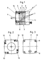
- An electric motor (FIG. 1) has a stator 3 formed from a laminated core 2, in which a rotatably mounted rotor with a shaft 4 is located.
- the stator laminated core 2 has laminations 5 or laminated groups formed from such laminations, which protrude beyond the outline of the remaining laminations 6 and form cooling fins 7.
- the sheets 6, as shown in detail in FIG. 4, are circular in their outer circumferential area, while the protruding sheets 5 (FIG. 5) have a polygonal and square outline shape in the exemplary embodiment.
- the square sheets 5 are formed here with their total edge length somewhat larger than the diameter of the round sheets 6. So they essentially protrude in the corner areas.
- the protruding metal sheets 5 have recesses 8 which allow fastening screws on the rear to access a front fastening flange 9.
- This mounting flange can be seen in Fig. 2 from its front and its corner areas with mounting holes 10 can also be seen from the rear of the electric motor 1 according to the view shown in Fig. 3, since 11 corresponding recesses in the sheets 5 and also in a rear end cover 8 are available.
- the angular sheets 5 also have aligned holes 12 in the mounting position, through which holes on the one hand on the fastening flange 9 and on the other hand on the end cover 11 engage gripping retaining bolts 13 to hold the entire stator 3 together (see FIGS. 1 and 2).
- these holes 12 are provided on both sides of the recesses 8 in the protruding corner areas. As can be seen in FIG. 2, only one of these two holes 12 is used in each corner area. However, the arrangement of two holes results in a position independence (turning position) of the sheets 5 during assembly.
- stator laminated core 2 is thus possible.
- hexagonal sheets can also be used.
- round and polygonal - a variety of different stator structures can be realized.
- the number of protruding sheets and their spacing from one another and their arrangement can be varied in relation to the longitudinal extent of the stator, wherein special cooling problems can also be solved.
Landscapes
- Engineering & Computer Science (AREA)
- Power Engineering (AREA)
- Iron Core Of Rotating Electric Machines (AREA)
- Transition And Organic Metals Composition Catalysts For Addition Polymerization (AREA)
- Valve Device For Special Equipments (AREA)
- Glass Compositions (AREA)
- Reciprocating, Oscillating Or Vibrating Motors (AREA)
Claims (7)
- Moteur électrique (1) avec un stator (3) composé d'un paquet de tôles (2) présentant des tôles circulaires (6), des tôles (5) ou des groupes de tôles de ce paquet (2) dépassant du périmètre des tôles restantes (6) et formant des ailettes de refroidissement (7), et avec une bride de fixation (9) comportant des trous de fixation (10) pour des vis de fixation et destinée à monter le moteur électrique (1), caractérisé en ce que les tôles saillantes (5) ont un contour polygonal et dépassent au moins avec leurs zones d'angle les tôles circulaires (6), et en ce que les tôles saillantes (5) présentent des découpes (8) dans leurs zones d'angle afin de pouvoir accéder par l'arrière aux vis de fixation sur la bride de fixation (9).
- Moteur électrique selon la revendication 1, caractérisé en ce que les tôles saillantes (5) présentent un périmètre carré.
- Moteur électrique selon la revendication 1 ou 2, caractérisé en ce que les découpes (8) dans les zones d'angle des tôles saillantes (5) n'ont pas de bord.
- Moteur électrique selon l'une des revendications 1 à 3, caractérisé en ce que, en position de montage, les tôles saillantes (5) présentent, dans leurs zones d'angle, des trous (12) en alignement pour des boulons de retenue (13).
- Moteur électrique selon l'une des revendications 1 à 4, caractérisé en ce que la longueur de côté des tôles saillantes (5) correspond environ au diamètre des tôles circulaires (6).
- Moteur électrique selon l'une des revendications 1 à 5, caractérisé en ce que les côtés des tôles saillantes (5) sont disposés de manière tangentielle par rapport au périmètre des tôles circulaires (6).
- Moteur électrique selon l'une des revendications 1 à 6, caractérisé en ce que des tôles circulaires (6) sont au moins disposées dans une zone d'extrémité axiale du stator (3) et qu'à cet endroit une bride terminale ou une bride de fixation (9) est montée de manière centrée.
Priority Applications (1)
| Application Number | Priority Date | Filing Date | Title |
|---|---|---|---|
| AT89104885T ATE91828T1 (de) | 1988-05-20 | 1989-03-18 | Elektromotor. |
Applications Claiming Priority (2)
| Application Number | Priority Date | Filing Date | Title |
|---|---|---|---|
| DE8806657U | 1988-05-20 | ||
| DE8806657U DE8806657U1 (de) | 1988-05-20 | 1988-05-20 | Elektromotor |
Publications (3)
| Publication Number | Publication Date |
|---|---|
| EP0342332A2 EP0342332A2 (fr) | 1989-11-23 |
| EP0342332A3 EP0342332A3 (en) | 1990-05-02 |
| EP0342332B1 true EP0342332B1 (fr) | 1993-07-21 |
Family
ID=6824281
Family Applications (1)
| Application Number | Title | Priority Date | Filing Date |
|---|---|---|---|
| EP89104885A Expired - Lifetime EP0342332B1 (fr) | 1988-05-20 | 1989-03-18 | Moteur électrique |
Country Status (3)
| Country | Link |
|---|---|
| EP (1) | EP0342332B1 (fr) |
| AT (1) | ATE91828T1 (fr) |
| DE (2) | DE8806657U1 (fr) |
Families Citing this family (6)
| Publication number | Priority date | Publication date | Assignee | Title |
|---|---|---|---|---|
| DE3844337A1 (de) * | 1988-12-30 | 1990-07-05 | Index Werke Kg Hahn & Tessky | Werkzeugmaschine mit gekuehlter motorspindel |
| DE4337463C2 (de) * | 1993-11-03 | 2002-01-03 | Vem Motors Gmbh | Ständer mit Belüftungseinrichtung für gehäuselose elektrische Maschine |
| GB2326983B (en) * | 1997-04-21 | 2001-01-17 | British Jeffrey Diamond 100 Lt | A switched reluctance motor and stator |
| FR2838252B1 (fr) * | 2002-04-03 | 2005-08-05 | Leroy Somer Moteurs | Machine electrique, notamment generatrice pour eolienne, comportant des ailettes de refroisissement s'etendant sensiblement perpendiculairement a l'axe de rotation du rotor |
| US6958562B1 (en) * | 2004-02-09 | 2005-10-25 | Vargo James R | Motor stator and heat sink system |
| DE102020202337A1 (de) | 2020-02-24 | 2021-08-26 | BSH Hausgeräte GmbH | Wäschepflegegerät mit elektrischem Antrieb |
Family Cites Families (2)
| Publication number | Priority date | Publication date | Assignee | Title |
|---|---|---|---|---|
| AT93285B (de) * | 1921-06-08 | 1923-06-25 | Armin Koenigsberg | Aus Blechen aufgebautes Statoreisen für elektrische Maschinen. |
| US3783318A (en) * | 1972-10-06 | 1974-01-01 | Marathon Electric Mfg | Laminated stator core for dynamoelectric machines |
-
1988
- 1988-05-20 DE DE8806657U patent/DE8806657U1/de not_active Expired
-
1989
- 1989-03-18 AT AT89104885T patent/ATE91828T1/de not_active IP Right Cessation
- 1989-03-18 EP EP89104885A patent/EP0342332B1/fr not_active Expired - Lifetime
- 1989-03-18 DE DE8989104885T patent/DE58904941D1/de not_active Expired - Fee Related
Non-Patent Citations (3)
| Title |
|---|
| PATENT ABSTRACTS OF JAPAN vol. 10, no. 50 (E-384) (2107), 27 Februar 1986; & JP-A- 60204236 * |
| PATENT ABSTRACTS OF JAPAN vol. 8, no. 115 (E-247) (1552), 29 May 1984; JP-A- 5928847 * |
| PATENT ABSTRACTS OF JAPAN vol. 9no. 230 (E-343) (1953), 17 September 1985; & JP-A- 6084934 * |
Also Published As
| Publication number | Publication date |
|---|---|
| DE8806657U1 (de) | 1988-07-07 |
| ATE91828T1 (de) | 1993-08-15 |
| DE58904941D1 (de) | 1993-08-26 |
| EP0342332A2 (fr) | 1989-11-23 |
| EP0342332A3 (en) | 1990-05-02 |
Similar Documents
| Publication | Publication Date | Title |
|---|---|---|
| DE69310627T2 (de) | Rotor eines synchronmotors | |
| DE69308380T2 (de) | Redundanter kommutierter Reluktanzmotor | |
| DE10297146B4 (de) | Stator für eine rotierende elektrische Maschine | |
| DE10207267A1 (de) | Rotor für einen synchronen Reluktanzmotor und sein Herstellungsverfahren | |
| DE69304889T3 (de) | Stator eines motors | |
| DE102010047551A1 (de) | Motor | |
| DE10130399A1 (de) | Statoranordnungen für Motoren | |
| DE1538799B2 (de) | Schrittschaltmotor | |
| DE112018005356T5 (de) | Anordnungsstruktur eines motorrotors | |
| DE3227076A1 (de) | Schrittschaltmotor | |
| DE60216188T2 (de) | Statoraufbau eines Schrittmotors mit Klauenpolen | |
| EP0342332B1 (fr) | Moteur électrique | |
| DE69607076T2 (de) | Synchronmotor vom Klauenpoltyp | |
| DE3905997C2 (fr) | ||
| DE2337776A1 (de) | Elektromotor, insbesondere fuer eine tragbare werkzeugmaschine | |
| CH664241A5 (de) | Rohrfoermiges gehaeuse einer dauermagnet-gleichstrommaschine. | |
| EP0254930A1 (fr) | Moteur électrique | |
| DE3520889C1 (de) | Elektrische Antriebsvorrichtung, insbesondere für Textilmaschinen | |
| DE102022115983B4 (de) | Kernstruktur des Motorrotors | |
| DE9003390U1 (de) | Elektrische Synchronmaschine mit einem Schenkelpolläufer | |
| DE2923033C2 (de) | Synchronmotor | |
| EP0344472A1 (fr) | Broche à entraînement individuel par un moteur électrique dans un métier à filer | |
| DE2738299A1 (de) | Einphasenschrittmotor, insbesondere fuer uhren | |
| DE4337463C2 (de) | Ständer mit Belüftungseinrichtung für gehäuselose elektrische Maschine | |
| DE60310352T2 (de) | Flacher Schrittmotor mit zwei in der gleichen Ebene liegenden Spulen |
Legal Events
| Date | Code | Title | Description |
|---|---|---|---|
| PUAI | Public reference made under article 153(3) epc to a published international application that has entered the european phase |
Free format text: ORIGINAL CODE: 0009012 |
|
| AK | Designated contracting states |
Kind code of ref document: A2 Designated state(s): AT CH DE FR GB IT LI |
|
| PUAL | Search report despatched |
Free format text: ORIGINAL CODE: 0009013 |
|
| AK | Designated contracting states |
Kind code of ref document: A3 Designated state(s): AT CH DE FR GB IT LI |
|
| 17P | Request for examination filed |
Effective date: 19900629 |
|
| 17Q | First examination report despatched |
Effective date: 19920511 |
|
| GRAA | (expected) grant |
Free format text: ORIGINAL CODE: 0009210 |
|
| AK | Designated contracting states |
Kind code of ref document: B1 Designated state(s): AT CH DE FR GB IT LI |
|
| PG25 | Lapsed in a contracting state [announced via postgrant information from national office to epo] |
Ref country code: GB Effective date: 19930721 Ref country code: FR Effective date: 19930721 Ref country code: IT Free format text: LAPSE BECAUSE OF FAILURE TO SUBMIT A TRANSLATION OF THE DESCRIPTION OR TO PAY THE FEE WITHIN THE PRE;WARNING: LAPSES OF ITALIAN PATENTS WITH EFFECTIVE DATE BEFORE 2007 MAY HAVE OCCURRED AT ANY TIME BEFORE 2007. THE CORRECT EFFECTIVE DATE MAY BE DIFFERENT FROM THE ONE RECORDED.SCRIBED TIME-LIMIT Effective date: 19930721 |
|
| REF | Corresponds to: |
Ref document number: 91828 Country of ref document: AT Date of ref document: 19930815 Kind code of ref document: T |
|
| REF | Corresponds to: |
Ref document number: 58904941 Country of ref document: DE Date of ref document: 19930826 |
|
| EN | Fr: translation not filed | ||
| GBV | Gb: ep patent (uk) treated as always having been void in accordance with gb section 77(7)/1977 [no translation filed] |
Effective date: 19930721 |
|
| PG25 | Lapsed in a contracting state [announced via postgrant information from national office to epo] |
Ref country code: AT Effective date: 19940318 |
|
| PG25 | Lapsed in a contracting state [announced via postgrant information from national office to epo] |
Ref country code: CH Effective date: 19940331 Ref country code: LI Effective date: 19940331 |
|
| PLBE | No opposition filed within time limit |
Free format text: ORIGINAL CODE: 0009261 |
|
| STAA | Information on the status of an ep patent application or granted ep patent |
Free format text: STATUS: NO OPPOSITION FILED WITHIN TIME LIMIT |
|
| 26N | No opposition filed | ||
| REG | Reference to a national code |
Ref country code: CH Ref legal event code: PL |
|
| PGFP | Annual fee paid to national office [announced via postgrant information from national office to epo] |
Ref country code: DE Payment date: 20020318 Year of fee payment: 14 |
|
| PG25 | Lapsed in a contracting state [announced via postgrant information from national office to epo] |
Ref country code: DE Free format text: LAPSE BECAUSE OF NON-PAYMENT OF DUE FEES Effective date: 20031001 |