EP0342376B1 - Capteur électronique de position associé à un système de commande - Google Patents
Capteur électronique de position associé à un système de commande Download PDFInfo
- Publication number
- EP0342376B1 EP0342376B1 EP89107080A EP89107080A EP0342376B1 EP 0342376 B1 EP0342376 B1 EP 0342376B1 EP 89107080 A EP89107080 A EP 89107080A EP 89107080 A EP89107080 A EP 89107080A EP 0342376 B1 EP0342376 B1 EP 0342376B1
- Authority
- EP
- European Patent Office
- Prior art keywords
- signal
- sensing elements
- engine
- electronic
- angular
- Prior art date
- Legal status (The legal status is an assumption and is not a legal conclusion. Google has not performed a legal analysis and makes no representation as to the accuracy of the status listed.)
- Expired - Lifetime
Links
- 239000000446 fuel Substances 0.000 claims abstract description 40
- 230000004044 response Effects 0.000 claims abstract description 28
- 238000002347 injection Methods 0.000 claims abstract description 27
- 239000007924 injection Substances 0.000 claims abstract description 27
- 238000001514 detection method Methods 0.000 claims description 9
- 230000003111 delayed effect Effects 0.000 claims description 6
- 238000002485 combustion reaction Methods 0.000 claims description 5
- 230000003287 optical effect Effects 0.000 claims description 4
- 230000009977 dual effect Effects 0.000 abstract description 9
- 230000008901 benefit Effects 0.000 description 5
- 238000010586 diagram Methods 0.000 description 5
- 230000004048 modification Effects 0.000 description 4
- 238000012986 modification Methods 0.000 description 4
- 230000000630 rising effect Effects 0.000 description 3
- 230000005355 Hall effect Effects 0.000 description 2
- 230000009471 action Effects 0.000 description 2
- 238000010276 construction Methods 0.000 description 2
- 230000003252 repetitive effect Effects 0.000 description 2
- 230000001360 synchronised effect Effects 0.000 description 2
- 230000007704 transition Effects 0.000 description 2
- 230000000712 assembly Effects 0.000 description 1
- 238000000429 assembly Methods 0.000 description 1
- 238000004364 calculation method Methods 0.000 description 1
- 230000008859 change Effects 0.000 description 1
- 230000005465 channeling Effects 0.000 description 1
- 238000004590 computer program Methods 0.000 description 1
- 238000012937 correction Methods 0.000 description 1
- 125000004122 cyclic group Chemical group 0.000 description 1
- 238000000034 method Methods 0.000 description 1
- 238000012545 processing Methods 0.000 description 1
- 238000012795 verification Methods 0.000 description 1
Images



Classifications
-
- F—MECHANICAL ENGINEERING; LIGHTING; HEATING; WEAPONS; BLASTING
- F02—COMBUSTION ENGINES; HOT-GAS OR COMBUSTION-PRODUCT ENGINE PLANTS
- F02D—CONTROLLING COMBUSTION ENGINES
- F02D41/00—Electrical control of supply of combustible mixture or its constituents
- F02D41/009—Electrical control of supply of combustible mixture or its constituents using means for generating position or synchronisation signals
-
- F—MECHANICAL ENGINEERING; LIGHTING; HEATING; WEAPONS; BLASTING
- F02—COMBUSTION ENGINES; HOT-GAS OR COMBUSTION-PRODUCT ENGINE PLANTS
- F02P—IGNITION, OTHER THAN COMPRESSION IGNITION, FOR INTERNAL-COMBUSTION ENGINES; TESTING OF IGNITION TIMING IN COMPRESSION-IGNITION ENGINES
- F02P15/00—Electric spark ignition having characteristics not provided for in, or of interest apart from, groups F02P1/00 - F02P13/00 and combined with layout of ignition circuits
- F02P15/008—Reserve ignition systems; Redundancy of some ignition devices
-
- F—MECHANICAL ENGINEERING; LIGHTING; HEATING; WEAPONS; BLASTING
- F02—COMBUSTION ENGINES; HOT-GAS OR COMBUSTION-PRODUCT ENGINE PLANTS
- F02P—IGNITION, OTHER THAN COMPRESSION IGNITION, FOR INTERNAL-COMBUSTION ENGINES; TESTING OF IGNITION TIMING IN COMPRESSION-IGNITION ENGINES
- F02P7/00—Arrangements of distributors, circuit-makers or -breakers, e.g. of distributor and circuit-breaker combinations or pick-up devices
- F02P7/06—Arrangements of distributors, circuit-makers or -breakers, e.g. of distributor and circuit-breaker combinations or pick-up devices of circuit-makers or -breakers, or pick-up devices adapted to sense particular points of the timing cycle
- F02P7/073—Optical pick-up devices
-
- F—MECHANICAL ENGINEERING; LIGHTING; HEATING; WEAPONS; BLASTING
- F02—COMBUSTION ENGINES; HOT-GAS OR COMBUSTION-PRODUCT ENGINE PLANTS
- F02P—IGNITION, OTHER THAN COMPRESSION IGNITION, FOR INTERNAL-COMBUSTION ENGINES; TESTING OF IGNITION TIMING IN COMPRESSION-IGNITION ENGINES
- F02P7/00—Arrangements of distributors, circuit-makers or -breakers, e.g. of distributor and circuit-breaker combinations or pick-up devices
- F02P7/06—Arrangements of distributors, circuit-makers or -breakers, e.g. of distributor and circuit-breaker combinations or pick-up devices of circuit-makers or -breakers, or pick-up devices adapted to sense particular points of the timing cycle
- F02P7/077—Circuits therefor, e.g. pulse generators
- F02P7/0775—Electronical verniers
Definitions
- a sensor system to reliably produce all three types of required signals without using an excessive number of sensors and without using an extensive amount of circuitry or requiring extensive microprocessor calculation time.
- a system should also be able to produce the required high resolution signal and reference signals even if a sensor element fails.
- Some prior systems such as U.S. patent 4,658,786 to Foss et al., take some corrective action in case of a detected fault, but typically the high resolution signal is lost if any sensing element producing that signal fails and/or such systems provide extra circuitry for normally using a different signal as a reference signal and guard against loss of this different reference signal by using, if a fault, the original reference signal.
- Some systems use simplified coincidence detection circuitry, such as U.S. patent 4,385,605 to Petrie et al., to provide a reference signal, but in the event of a sensing element failure, no reference signal is provided.
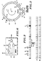
- the rotating wheel 11 has three slots having an angular width b corresponding to 3 degrees, one slot having an angular width c corresponding to 7 degrees and thirty-two slots having an angular width a corresponding to 1 degree.
- a plurality of the 1 degree slots a are provided between each of the slots b and c on the wheel 11.
- the distance between radial straight leading edges 15' of each of the slots 15 is an angular width spacing e corresponding to 10 degrees, and the rotating wheel 11 is rotated about its axis 11' in an angular direction 11", as indicated in FIGS. 1 and 2, such that the leading edges 15' of the slots correspond to those edges of the slots which first pass by the sensing elements 13 and 14.
- the fault detector 29 determines that a fault exists resulting in the absence of signal transitions at the terminal A, a high logic level will be produced at the terminal 32 indicative of such a fault condition.
- the switch 27, which previously provided the signal at the terminal A to the terminal 28 for utilization by the spark timing control 16 and fuel injection control circuit 25, will now provide the duplicate, but slightly delayed, sensor signal B at the terminal B for use by the spark timing and fuel control circuits 16 and 25. This is accomplished in the following manner.
- FIG. 7 illustrates a preferred embodiment for the spark timing control 16.
- the main function of the control 16 is to receive high resolution engine position signals (A or B) provided at the terminal 28 and produce suitable spark timing occurrence control signals. These controls signals are provided at an output terminal 41 which is connected as an input to the electronic spark distributor 23 that presents these signals, in an appropriate sequential manner, to each of the engine cylinders 17 through 20.
- a or B engine position signals
- These controls signals are provided at an output terminal 41 which is connected as an input to the electronic spark distributor 23 that presents these signals, in an appropriate sequential manner, to each of the engine cylinders 17 through 20.
- this general overall function of the spark timing control 16 such a function can be implemented by numerous well-known prior art circuits.
- FIG. 7 illustrates the spark timing control circuit 16 as including a long versus short pulse detector 50 which, as generally indicated previously, will receive the signal at the terminal 28 and distinguish the top-dead center longer pulses attributable to the slots b or c, from the shorter duration pulses attributable to the slots a.
- this can readily be implemented by utilizing the techniques discussed in the Hunninghaus et al. U.S. patent 4,628,269.
- this function will be implemented by a programmed computer which will distinguish between receiving a signal pulse having a predetermined longer duration, by a factor of at least 1.5, than preceding and subsequent received signal pulses.
- the top-dead center reference information produced by the circuit 50 can be utilized by the spark timing control 16 itself.
Landscapes
- Engineering & Computer Science (AREA)
- Chemical & Material Sciences (AREA)
- Combustion & Propulsion (AREA)
- Mechanical Engineering (AREA)
- General Engineering & Computer Science (AREA)
- Combined Controls Of Internal Combustion Engines (AREA)
- Control Of Stepping Motors (AREA)
- Control Of Position Or Direction (AREA)
- Control Of Electric Motors In General (AREA)
- Vehicle Body Suspensions (AREA)
Claims (13)
- Ensemble électronique à capteur de position, comprenant :une roue (11) entraînée en rotation autour d'un axe (11'), la roue ayant plusieurs parties prédéterminées (15) ayant des largeurs angulaires prédéterminées,un dispositif capteur (12) placé en position fixe par rapport à la roue (11) et près de celle-ci, le dispositif capteur comprenant au moins un premier et un second élément de détection (13, 14) détectant chacun indépendamment le passage de chacune des parties prédéterminées (15) par l'élément de détection et produisant en réponse un signal ayant des impulsions de signalisation (A, B) qui correspondent à la largeur angulaire des parties prédéterminées détectées et qui se produisent pendant cette largeur angulaire, etun dispositif (21) de coïncidence destiné à donner un premier signal de référence (en 22) à la suite de la production simultanée, par les premier et second éléments de détection de conditions d'état logique prédéterminé des impulsions de signalisation du capteur,l'ensemble capteur étant caractérisé par des largeurs angulaires comprenant au moins trois largeurs angulaires différentes a, b et c, la largeur angulaire a étant inférieure à la largeur angulaire b qui est elle-même inférieure à la largeur angulaire c, etles premier et second éléments (13, 14) de détection sont séparés par une distance d qui correspond à une largeur angulaire inférieure à la largeur angulaire c mais supérieure à la largeur angulaire a et supérieure à la largeur angulaire b, etun dispositif (50) destiné à recevoir les impulsions de signalisation de capteur données par au moins l'un des premier et second éléments de détection (13, 14) et destiné à donner en réponse un second signal de référence, différent du premier signal de référence (en 22), représentatif du passage de chaque partie prédéterminée de largeur b par le dispositif capteur, si bien que des informations relatives à la position angulaire de la roue sont obtenues à l'aide des premier et second signaux de référence au moins.
- Ensemble électronique à capteur de position selon la revendication 1, dans lequel le second dispositif (50) à signal de référence comprend un ordinateur programmé afin qu'il distingue la réception d'une impulsion de signalisation ayant une durée prédéterminée supérieure à celle d'une impulsion précédente de signalisation reçue.
- Ensemble électronique à capteur de position selon la revendication 1 ou 2, dans lequel lesdites parties prédéterminées (15) sont disposées uniformément autour de la roue (11) avec des bords avant, par rapport aux éléments de détection (13, 14), séparés par une largeur angulaire e qui est supérieure à la largeur angulaire d.
- Ensemble électronique à capteur de position selon la revendication 1, 2 ou 3, dans lequel lesdites parties prédéterminées (15) sont placées sur la roue (11) de manière que chacune des parties prédéterminées ayant des largeurs angulaires b ou c soit séparée d'une autre des parties prédéterminées ayant les largeurs angulaires b ou c par plusieurs parties prédéterminées ayant chacune la largeur angulaire a.
- Ensemble électronique à capteur de position selon la revendication 4, dans lequel les éléments de détection (13, 14) comprennent des éléments de détection optique qui sont montés l'un près de l'autre dans un boîtier solidaire (12) de capteur, et dans lequel les parties prédéterminées (15) sont des fentes formées dans la roue, les fentes délimitant une piste circulaire de détection formée sur la roue pour les éléments de détection.
- Ensemble électronique à capteur de position selon la revendication 4 ou 5, dans lequel plusieurs parties prédéterminées (15) ont la largeur angulaire b, et les éléments de détection (13, 14) et les parties prédéterminées ont une configuration telle que les impulsions de signalisation données par le second élément de détection (13 ou 14) en fonction des parties prédéterminées comportent des impulsions de signalisation transmises par le premier élément de détection (14 ou 13) avec un retard (t₀-t₁) lié à la vitesse de rotation de la roue (11) et à la largeur angulaire d.
- Ensemble électronique de commande de moteur qui comprend un ensemble électronique à capteur de position selon l'une quelconque des revendications précédentes, dans lequel la roue (11) est entraînée en rotation autour de l'axe (11') par un moteur à plusieurs cylindres, et l'ensemble comprend un dispositif (16-25) de commande de moteur destiné à utiliser des impulsions de signalisation de l'un au moins des premier et second éléments de détection (13, 14) et l'un au moins des premier et second signaux de référence pour la commande de la combustion du carburant dans les cylindres (17-20) du moteur.
- Ensemble électronique de commande de moteur selon la revendication 7, dans lequel le dispositif (16-25) de commande de moteur comprend un dispositif (16, 25) d'injection de carburant destiné à régler l'injection du carburant dans les cylindres (17-20) et comprenant un dispositif électronique distributeur (24) à injecteur de carburant destiné à transmettre sélectivement des signaux d'injection de carburant créés par le dispositif d'injection de carburant (16, 25) à différents cylindres (17-20) du moteur en fonction du second signal de référence au moins.
- Ensemble électronique de commande de moteur selon la revendication 7 ou 8, dans lequel le nombre de parties prédéterminées (15) ayant des largeurs angulaires inférieures à la largeur angulaire c est nettement supérieur au nombre de cylindres du moteur.
- Ensemble électronique de commande de moteur, comprenant :l'ensemble capteur de position de moteur selon la revendication 1, destiné à détecter la position de la roue (11) entraînée en rotation autour de l'axe (11') par un moteur,un dispositif (17-25) de commande de fonctionnement de moteur en fonction du premier signal de référence au moins (en 22) et des impulsions de signalisation (A, B) de l'un au moins des premier et second éléments de détection (13, 14),un dispositif (29) de détection d'une panne des impulsions de signalisation provenant de l'un des premier et second éléments de détection, etun dispositif (40) qui, après détection d'une panne, transmet un signal de référence de remplacement (après 45) au dispositif de commande de moteur (17-25) afin qu'il soit utilisé à la place du premier signal de référence (en 22).
- Ensemble électronique de commande de moteur selon la revendication 10, dans lequel le dispositif (40) destiné à transmettre le signal de référence de remplacement comporte un dispositif (42) destiné à compter, en cas de panne des impulsions de signalisation provenant de l'un des premier et second éléments de détection, des impulsions de signalisation données par l'autre des éléments de détection, et transmettant le signal de référence de remplacement lorsque le comptage dépasse une valeur prédéterminée.
- Ensemble électronique de commande de moteur selon la revendication 11, qui comporte un dispositif (27) qui, à la suite d'une détection de panne, sélectionne les impulsions de signalisation données par l'autre des éléments de détection à la place des impulsions de signalisation données par le premier au moins des éléments de détection, afin qu'elles soient utilisées par le dispositif de commande de moteur (17-25).
- Ensemble électronique de commande de moteur selon la revendication 12, dans lequel les impulsions de signalisation données en l'absence de panne par l'un des éléments de détection sont les impulsions de signalisation données par l'autre des éléments de détection, mais retardées dans le temps d'une quantité (t₀-t₁) liée à la vitesse de rotation de la roue (11), et les deux éléments de détection sont séparés par une largeur angulaire prédéterminée (d) qui détermine la valeur du retard.
Priority Applications (2)
| Application Number | Priority Date | Filing Date | Title |
|---|---|---|---|
| EP95110314A EP0682180A3 (fr) | 1988-05-16 | 1989-04-20 | Capteur électronique de position associé à un système de commande. |
| EP98112946A EP0879956B1 (fr) | 1988-05-16 | 1989-04-20 | Capteur électronique de position associé à système de commande |
Applications Claiming Priority (2)
| Application Number | Priority Date | Filing Date | Title |
|---|---|---|---|
| US19423788A | 1988-05-16 | 1988-05-16 | |
| US194237 | 1988-05-16 |
Related Child Applications (2)
| Application Number | Title | Priority Date | Filing Date |
|---|---|---|---|
| EP95110314A Division EP0682180A3 (fr) | 1988-05-16 | 1989-04-20 | Capteur électronique de position associé à un système de commande. |
| EP95110314.2 Division-Into | 1989-04-20 |
Publications (3)
| Publication Number | Publication Date |
|---|---|
| EP0342376A2 EP0342376A2 (fr) | 1989-11-23 |
| EP0342376A3 EP0342376A3 (fr) | 1991-04-03 |
| EP0342376B1 true EP0342376B1 (fr) | 1996-02-14 |
Family
ID=22716830
Family Applications (3)
| Application Number | Title | Priority Date | Filing Date |
|---|---|---|---|
| EP89107080A Expired - Lifetime EP0342376B1 (fr) | 1988-05-16 | 1989-04-20 | Capteur électronique de position associé à un système de commande |
| EP95110314A Withdrawn EP0682180A3 (fr) | 1988-05-16 | 1989-04-20 | Capteur électronique de position associé à un système de commande. |
| EP98112946A Expired - Lifetime EP0879956B1 (fr) | 1988-05-16 | 1989-04-20 | Capteur électronique de position associé à système de commande |
Family Applications After (2)
| Application Number | Title | Priority Date | Filing Date |
|---|---|---|---|
| EP95110314A Withdrawn EP0682180A3 (fr) | 1988-05-16 | 1989-04-20 | Capteur électronique de position associé à un système de commande. |
| EP98112946A Expired - Lifetime EP0879956B1 (fr) | 1988-05-16 | 1989-04-20 | Capteur électronique de position associé à système de commande |
Country Status (3)
| Country | Link |
|---|---|
| EP (3) | EP0342376B1 (fr) |
| AT (1) | ATE134251T1 (fr) |
| DE (2) | DE68929420T2 (fr) |
Families Citing this family (3)
| Publication number | Priority date | Publication date | Assignee | Title |
|---|---|---|---|---|
| US5806488A (en) * | 1992-12-14 | 1998-09-15 | Transcom Gas Technologies Pty | Electronic engine timing |
| RU2260784C2 (ru) * | 2003-11-19 | 2005-09-20 | Открытое акционерное общество "КАМАЗ" | Устройство регистрации частоты вращения коленчатого вала и верхней мертвой точки движения поршня (вмт) двигателя внутреннего сгорания |
| CN114953150B (zh) * | 2022-06-13 | 2024-03-22 | 陈祥 | 一种全自动压瓦机及制瓦生产线 |
Citations (1)
| Publication number | Priority date | Publication date | Assignee | Title |
|---|---|---|---|---|
| US4656634A (en) * | 1985-06-14 | 1987-04-07 | Motorola, Inc. | Skew insensitive fault detect and signal routing device |
Family Cites Families (17)
| Publication number | Priority date | Publication date | Assignee | Title |
|---|---|---|---|---|
| DE2458946C2 (de) * | 1974-12-12 | 1983-02-17 | Siemens AG, 1000 Berlin und 8000 München | Optischer Analog-Festwertspeicher |
| JPS6053190B2 (ja) * | 1976-10-15 | 1985-11-25 | 株式会社デンソー | 回転基準位置検出装置 |
| FR2374528A1 (fr) * | 1976-12-17 | 1978-07-13 | Cii | Systeme d'allumage electronique et moteur a combustion interne equipe d'un tel systeme |
| US4168682A (en) | 1977-03-22 | 1979-09-25 | Motorola, Inc. | Electronic ignition timing system using digital rate multiplication |
| US4241708A (en) | 1979-04-12 | 1980-12-30 | Motorola, Inc. | Ignition spark timing circuit with switchable hysteresis |
| US4231332A (en) | 1979-06-15 | 1980-11-04 | Motorola, Inc. | Spark and dwell ignition control system using digital circuitry |
| US4338906A (en) | 1979-10-29 | 1982-07-13 | Nathan Cox | Fuel charge preheater |
| US4338813A (en) | 1980-09-02 | 1982-07-13 | Motorola Inc. | Electronic engine synchronization and timing apparatus |
| US4378004A (en) * | 1981-02-23 | 1983-03-29 | Motorola Inc. | Engine control system with cylinder identification apparatus |
| US4385605A (en) | 1981-10-13 | 1983-05-31 | Motorola Inc. | Electronic ignition input logic |
| JPS5870052A (ja) * | 1981-10-22 | 1983-04-26 | Kokusan Denki Co Ltd | 多気筒内燃機関用点火時期制御装置 |
| US4553426A (en) | 1984-05-23 | 1985-11-19 | Motorola, Inc. | Reference pulse verification circuit adaptable for engine control |
| US4628269A (en) | 1984-05-23 | 1986-12-09 | Motorola, Inc. | Pulse detector for missing or extra pulses |
| JPS62159772A (ja) * | 1986-01-08 | 1987-07-15 | Hitachi Ltd | 回転信号検出装置 |
| DE3602292A1 (de) * | 1986-01-25 | 1987-08-06 | Audi Ag | Geberanordnung |
| US4658786A (en) | 1986-03-25 | 1987-04-21 | Motorola, Inc. | Loss of input signal detection and response system for use with distributorless ignition systems |
| JPS62225770A (ja) * | 1986-03-28 | 1987-10-03 | Hitachi Ltd | エンジン制御装置 |
-
1989
- 1989-04-20 EP EP89107080A patent/EP0342376B1/fr not_active Expired - Lifetime
- 1989-04-20 EP EP95110314A patent/EP0682180A3/fr not_active Withdrawn
- 1989-04-20 DE DE68929420T patent/DE68929420T2/de not_active Expired - Lifetime
- 1989-04-20 EP EP98112946A patent/EP0879956B1/fr not_active Expired - Lifetime
- 1989-04-20 AT AT89107080T patent/ATE134251T1/de not_active IP Right Cessation
- 1989-04-20 DE DE68925658T patent/DE68925658T2/de not_active Expired - Lifetime
Patent Citations (1)
| Publication number | Priority date | Publication date | Assignee | Title |
|---|---|---|---|---|
| US4656634A (en) * | 1985-06-14 | 1987-04-07 | Motorola, Inc. | Skew insensitive fault detect and signal routing device |
Also Published As
| Publication number | Publication date |
|---|---|
| DE68929420D1 (de) | 2002-09-05 |
| EP0682180A2 (fr) | 1995-11-15 |
| EP0342376A2 (fr) | 1989-11-23 |
| EP0879956B1 (fr) | 2002-07-31 |
| ATE134251T1 (de) | 1996-02-15 |
| EP0342376A3 (fr) | 1991-04-03 |
| DE68929420T2 (de) | 2002-12-05 |
| EP0682180A3 (fr) | 1996-01-24 |
| DE68925658T2 (de) | 1996-09-19 |
| EP0879956A1 (fr) | 1998-11-25 |
| DE68925658D1 (de) | 1996-03-28 |
Similar Documents
| Publication | Publication Date | Title |
|---|---|---|
| US4941445A (en) | Electronic position sensor assembly and engine control system | |
| US4378004A (en) | Engine control system with cylinder identification apparatus | |
| KR100238735B1 (ko) | N 실린더를 갖는 내연기관의 실린더 식별용 전달장치 | |
| US4553426A (en) | Reference pulse verification circuit adaptable for engine control | |
| JPH0412411Y2 (fr) | ||
| US4700305A (en) | Position displacement and speed sensor system, particularly for combination with an automotive engine control computer | |
| US5269274A (en) | Method and device for an open-loop control system for an internal combustion engine | |
| US4385605A (en) | Electronic ignition input logic | |
| US5099811A (en) | Method for firing spark plugs | |
| US5647322A (en) | Internal combustion engine control apparatus | |
| US4644917A (en) | Method and apparatus for controlling an internal combustion engine | |
| US4750467A (en) | Internal combustion engine ignition system | |
| US4690124A (en) | Spark control system for an engine | |
| US4959996A (en) | Control signal generator for an internal combustion engine | |
| US4711226A (en) | Internal combustion engine ignition system | |
| US5119670A (en) | Crankshaft angular position detecting apparatus | |
| JP2813210B2 (ja) | 内燃機関用気筒識別装置 | |
| US4979487A (en) | Ignition controlling apparatus for multi-cylinder internal combustion engine | |
| EP0879956B1 (fr) | Capteur électronique de position associé à système de commande | |
| US4327687A (en) | Timing system for process control in internal combustion engines | |
| JP2690315B2 (ja) | 内燃機関に対する点火装置および噴射装置 | |
| EP0061978B1 (fr) | Système de déclencheur en quadrature pour l'injection intermittente de carburant | |
| EP0506165B1 (fr) | Système de commande de l'instant d'allumage | |
| EP0115827B1 (fr) | Méthode de commande d'un moteur à combustion interne | |
| KR940000347B1 (ko) | 내연기관제어방법 |
Legal Events
| Date | Code | Title | Description |
|---|---|---|---|
| PUAI | Public reference made under article 153(3) epc to a published international application that has entered the european phase |
Free format text: ORIGINAL CODE: 0009012 |
|
| AK | Designated contracting states |
Kind code of ref document: A2 Designated state(s): AT BE CH DE FR GB IT LI LU NL SE |
|
| PUAL | Search report despatched |
Free format text: ORIGINAL CODE: 0009013 |
|
| AK | Designated contracting states |
Kind code of ref document: A3 Designated state(s): AT BE CH DE FR GB IT LI LU NL SE |
|
| 17P | Request for examination filed |
Effective date: 19911001 |
|
| 17Q | First examination report despatched |
Effective date: 19931111 |
|
| ITF | It: translation for a ep patent filed | ||
| GRAA | (expected) grant |
Free format text: ORIGINAL CODE: 0009210 |
|
| AK | Designated contracting states |
Kind code of ref document: B1 Designated state(s): AT BE CH DE FR GB IT LI LU NL SE |
|
| PG25 | Lapsed in a contracting state [announced via postgrant information from national office to epo] |
Ref country code: NL Free format text: LAPSE BECAUSE OF FAILURE TO SUBMIT A TRANSLATION OF THE DESCRIPTION OR TO PAY THE FEE WITHIN THE PRESCRIBED TIME-LIMIT Effective date: 19960214 Ref country code: LI Free format text: LAPSE BECAUSE OF FAILURE TO SUBMIT A TRANSLATION OF THE DESCRIPTION OR TO PAY THE FEE WITHIN THE PRESCRIBED TIME-LIMIT Effective date: 19960214 Ref country code: CH Free format text: LAPSE BECAUSE OF FAILURE TO SUBMIT A TRANSLATION OF THE DESCRIPTION OR TO PAY THE FEE WITHIN THE PRESCRIBED TIME-LIMIT Effective date: 19960214 Ref country code: BE Effective date: 19960214 Ref country code: AT Effective date: 19960214 |
|
| REF | Corresponds to: |
Ref document number: 134251 Country of ref document: AT Date of ref document: 19960215 Kind code of ref document: T |
|
| XX | Miscellaneous (additional remarks) |
Free format text: TEILANMELDUNG 95110314.2 EINGEREICHT AM 20/04/89. |
|
| REF | Corresponds to: |
Ref document number: 68925658 Country of ref document: DE Date of ref document: 19960328 |
|
| PG25 | Lapsed in a contracting state [announced via postgrant information from national office to epo] |
Ref country code: LU Free format text: LAPSE BECAUSE OF NON-PAYMENT OF DUE FEES Effective date: 19960430 |
|
| PG25 | Lapsed in a contracting state [announced via postgrant information from national office to epo] |
Ref country code: SE Effective date: 19960514 |
|
| ET | Fr: translation filed | ||
| NLV1 | Nl: lapsed or annulled due to failure to fulfill the requirements of art. 29p and 29m of the patents act | ||
| REG | Reference to a national code |
Ref country code: CH Ref legal event code: PL |
|
| PLBE | No opposition filed within time limit |
Free format text: ORIGINAL CODE: 0009261 |
|
| STAA | Information on the status of an ep patent application or granted ep patent |
Free format text: STATUS: NO OPPOSITION FILED WITHIN TIME LIMIT |
|
| 26N | No opposition filed | ||
| REG | Reference to a national code |
Ref country code: GB Ref legal event code: IF02 |
|
| PGFP | Annual fee paid to national office [announced via postgrant information from national office to epo] |
Ref country code: GB Payment date: 20080317 Year of fee payment: 20 |
|
| PGFP | Annual fee paid to national office [announced via postgrant information from national office to epo] |
Ref country code: DE Payment date: 20080430 Year of fee payment: 20 |
|
| PGFP | Annual fee paid to national office [announced via postgrant information from national office to epo] |
Ref country code: IT Payment date: 20080419 Year of fee payment: 20 |
|
| PGFP | Annual fee paid to national office [announced via postgrant information from national office to epo] |
Ref country code: FR Payment date: 20080403 Year of fee payment: 20 |
|
| REG | Reference to a national code |
Ref country code: GB Ref legal event code: PE20 Expiry date: 20090419 |
|
| PG25 | Lapsed in a contracting state [announced via postgrant information from national office to epo] |
Ref country code: GB Free format text: LAPSE BECAUSE OF EXPIRATION OF PROTECTION Effective date: 20090419 |