EP0342449A2 - Triangle de signalisation pliable - Google Patents
Triangle de signalisation pliable Download PDFInfo
- Publication number
- EP0342449A2 EP0342449A2 EP89108120A EP89108120A EP0342449A2 EP 0342449 A2 EP0342449 A2 EP 0342449A2 EP 89108120 A EP89108120 A EP 89108120A EP 89108120 A EP89108120 A EP 89108120A EP 0342449 A2 EP0342449 A2 EP 0342449A2
- Authority
- EP
- European Patent Office
- Prior art keywords
- warning triangle
- spring
- feet
- triangle according
- carrier plate
- Prior art date
- Legal status (The legal status is an assumption and is not a legal conclusion. Google has not performed a legal analysis and makes no representation as to the accuracy of the status listed.)
- Granted
Links
Images


Classifications
-
- B—PERFORMING OPERATIONS; TRANSPORTING
- B60—VEHICLES IN GENERAL
- B60Q—ARRANGEMENT OF SIGNALLING OR LIGHTING DEVICES, THE MOUNTING OR SUPPORTING THEREOF OR CIRCUITS THEREFOR, FOR VEHICLES IN GENERAL
- B60Q7/00—Arrangement or adaptation of portable emergency signal devices on vehicles
- B60Q7/005—Devices without lamps
Definitions
- the invention relates to a collapsible warning triangle for carrying in motor vehicles, with three red reflective strips, one of which is fixedly attached to a metal support plate or itself serves as a support plate, a bearing on both sides and on both ends of the support plate and pivotable in the bearings Stored feet, which can be swung out of their position on the support plate and swung out to the side up to a stop.
- Such a collapsible warning triangle is known from Finnish patent application No. 86 3587, in which feet are articulated on the ends of the lower reflective triangular strip or a support plate connected to it on both sides. After swinging out, the four feet ensure that the warning triangle remains stable even in the event of intermittent wind.
- the four feet have to be swung out if necessary, that is to say in the event of an accident or a breakdown.
- Technically inexperienced people therefore often find it difficult to set up the warning triangle, especially if they are strained nervously shortly after an accident.
- the present invention has for its object to provide a collapsible warning triangle for carrying in motor vehicles, the installation of which is facilitated.
- the warning triangle should be able to be set up quickly and easily, even by technically inexperienced persons under the nervous stresses associated with an accident.
- the warning triangle should have a small space after being merged, in particular can only be accommodated in a flat quiver. Further advantages of the warning triangle according to the invention result from the following description.
- each pedestal is pretensioned in the pivoting direction by a spring and can be pivoted out automatically up to a stop.
- the folded warning triangle is carried in a quiver-shaped container in a known manner.
- the feet pretensioned in the pivoting direction are held in their pivoted-in positions by the container wall.
- the feet automatically swing out as far as their stop by the spring force, so that the formation of the triangle is made considerably easier.
- the person involved in the installation can concentrate on the erection of the two red reflective strips.
- the spring is designed as a helical torsion spring.
- the helical torsion spring takes up little space, which does not increase when the feet are swung out.
- the four helical springs do not cause an increase in the thickness of the warning triangle in the collapsed form.
- the folded warning triangle can therefore be accommodated in a relatively flat container.
- each base is angled near one end and its angled part is mounted in a joint.
- the joints are convenient simple friction joints that are relatively inexpensive to manufacture.
- the torsion spring at least partially surrounds the angled part of the base, one end of the prestressed spring is connected in a rotationally fixed manner to the base and the other end of the spring is supported in a bearing body.
- the non-rotatable attack of the one spring end on the base expediently takes place in that this spring end positively embraces the angled end of the base.
- at least the angled part of the base has a non-circular, in particular angular cross section.
- the bearings provided in pairs at each end of the carrier plate are preferably formed in a bearing body which is fixedly attached to the carrier plate, in particular is firmly inserted into a recess in the carrier plate.
- This bearing body containing the two pedestal bearings and torsion springs and preferably also the two stops can be manufactured inexpensively from plastic, for example by injection molding.
- the recess in the carrier plate is, for example, a slot that runs upward from its lower edge.
- the bearing body then has a web that connects its two symmetrical bearings on both sides of the carrier plate. By inserting the web in the slot of the carrier plate, the bearing body is firmly mounted on the carrier plate.
- the angled part of the base and the torsion spring surrounding this part are encapsulated in the bearing body.
- the bearing body is thus designed as a double housing in which the angled base parts are contained with their torsion springs. In this way, the torsion springs are largely protected from dirt and moisture.
- the pivot axes of the feet are inclined at each of the two ends of the carrier plate at an acute angle ⁇ to the plane of the carrier plate.
- the two axes are essentially V-shaped symmetrical to the carrier plate.
- the feet are preferably made of steel wire. Gusts of wind can be easily absorbed by the resilient feet without the warning triangle standing on the road being moved or tipping over.
- Steel wire stands also have a low weight and require little space after the triangle has been folded and accommodated in the quiver.
- the steel wire expediently has a cross section flattened on both sides over its entire length or only in its angled part.
- the thickness of the steel wire is generally in the range of 3 to 7 mm, preferably 5 mm.
- the feet expediently have a part which adjoins the bearing body and runs parallel to the lower edge of the support plate and a bent part. The ends of the feet are bent down again so that the required floor clearance of the triangle is guaranteed after the feet have been swung out.
- plastic caps are placed on the free ends of the feet and that each cap has an opening on the underside that leaves the foot end edge free. The plastic caps serve to protect the user. They prevent the user from being injured by the foot end edges when the feet swivel out automatically. However, the cut-out opening allows this edge to come into engagement with the rough road surface when the triangle is set up, so that there is sufficient stamina under the influence of wind.
- an at least one spring turn, preferably two spring turns, transverse groove is formed on the angled part of the base and the spring turns in the area of the transverse groove have essentially straight-line areas which lie in the transverse groove when the spring is subjected to torsional stress and secure the angled base part against axial displacement in the bore of the bearing body.
- two strips provided with retroreflective surfaces can be pivoted about joints located on the support plate, the joints lie on the support plate in the height region of their strip parts and the strip is provided at its articulation end with a projection that extends beyond its night reflector surface and in which its joint is arranged.
- the joints of the two pivotable strips By arranging the joints of the two pivotable strips at different heights, ie at different distances from the lower edge of the carrier plate, the strips can be swung behind or in front of the carrier plate until they are aligned one behind the other. Since the strip part 1 carrying the night reflector surface on the front ends per se in the upper region of the carrier plate, a molding is provided which extends so deep that the hinge point of the bar can be arranged sufficiently deep in this molding.
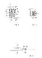
- the embodiment of the warning triangle according to the invention shown in FIGS. 1 and 2 has three red, retroreflective strips 1-3, to which the strips 1 a , 2 a and 3 a with a red fluorescent surface are integrally formed.
- the plastic strip 3.3 a is attached to the front of a steel support plate 8, the red fluorescent 3 a can also be replaced by a fluorescent film applied directly to the carrier plate 8.
- the bar 1.1 a is pivotable about the hinge 5, the bar 2.2 a around the hinge 6. If the bars 1.1 a and 2.2 a are pivoted up into the position shown in Figure 1, they can by Push button 7 are connected.
- each of the two bearing bodies 9 and 10 two feet are pivotally supported, of which only the two feet 11 and 12 articulated in front of the support plate 8 are shown in the swiveled out or swiveled-in position in FIGS. 1 and 2, and the articulated feet behind the support plate 8 however, they are designed in the same way as the feet 11 and 12.
- the feet 11 and 12 are simplified, that is to say without the bends shown in FIG. 2.
- the feet 11 and 12 have an angled part accommodated in the bearing bodies 9 and 10, respectively, which can be seen more clearly in FIG.
- FIG. 3 shows the top view of the warning triangle with the feet 11-14 pivoted out as far as possible.
- the swung-out feet extend far in front of and behind the triangular structure 1-8 and therefore give it a good, resilient stability.
- the bearing body 10 is formed symmetrically to the central plane, ie to the support plate 8, and contains the same bearings for the two feet 12 and 14 in front of and behind this plate.
- the bearing body 10 is firmly inserted from below into a slot formed in the carrier plate 8. It has two bores 15 and 16, which serve as pivot bearings for the angled end parts 12 a and 14 a of the feet 12 , 14.
- the bearing bores 15 and 14 and thus also the pivot axes of the feet 12 and 14 are slightly inclined to the plane of the support plate 8, the angle of inclination ⁇ in the range from 1 to 20 °, preferably in the range from 5 to 15 °.
- the bearing bores 15 and 16 go up into chamber bores 17 and 18, the diameter of which is larger than that of the bearing bores 15 and 16, respectively.
- the angled end parts 12 a and 14 a project with their ends concentrically into the chamber bores 17 and 18 and carry a spring ring 19 and 20 at the upper end.
- a torsion coil spring 23 or 24 is arranged between a shoulder 21 and 22 between the bores 15/17 and 16 / 18 and the spring ring 19 or 20, a torsion coil spring 23 or 24 is arranged.
- the base end parts 12 a and 14 a have a circular cross section with flattened parallel side surfaces.
- the uppermost turn of the springs 23 and 24 is in a form-fitting manner against the end part 12 a or 14 a , so that a non-rotatable connection is established between the spring 23 or 24 and end part 12 a or 14 a .
- the lower end 23 a and 24 a of the helical spring 23 and 24 is rectilinear and protrudes into a recess 25 and 26 in the bearing body 10 and supports on the wall of this decrease.
- the springs 23 and 24 are inserted under torsional stress into the chamber bores 17 and 18, respectively.
- the torsion springs can also be located outside the bearing body, for example below or above it, if the angled end parts 12 a or 14 a extend through the bearing body. It is also possible to clamp each of the two feet at one end of the support plate 8 by means of a single torsion spring, one end of the spring tensioning the horizontal part 12 b of one base 12 and the end of the spring stretching the horizontal part 14 b of the other base 12.
- the joints 5 and 6 are arranged asymmetrically: the joint 5, with which the strips 1 , 1 a are articulated on the carrier plate 8, is arranged substantially lower, ie at a smaller distance from the lower edge 8 a of the carrier plate, than the joint 6 , with which the bars 2.2 a are articulated. It is also important that the strips 1.1 a and 3.3 a in point 5 are connected by only one rivet.
- FIGS. 7 and 8 show an embodiment which has been somewhat modified compared to FIG. 4 and in which the spring washers 19 and 20 have been omitted. Instead, the angled end parts of the feet, of which only the end part 14 a is shown, have a transverse groove 31 at the upper end.
- the torsion coil spring 24 has two turns 24 b in the region of the transverse groove 31 with approximately straight winding parts, as can be seen in FIG. 8. Since the torsion spring 24 is under torsional stress after insertion into the chamber bore 18, two rectilinear regions of the windings 24 b lie in the transverse groove 31 and thereby fix the bent part 14 a in the bore 16 against axial displacement. The effect achieved in this way is therefore the same as that of the spring ring 20 shown in FIG. 4.
- FIG. 9 shows the downwardly bent end part 11 d of a pedestal 11, on the end of which a plastic cap 33 is placed.
- This plastic cap is provided with an opening 34, which leaves the end edge 11 e of the pedestal 11 in the lower part, ie the part facing the road surface 32, so that the edge 11 e can come into engagement with the rough road surface and the necessary stability of the warning triangle results .
- the cap 33 prevents a user of the warning triangle from being injured by the ends of the feet 11-14 when they swing out automatically.
- FIG. 10 shows the lower right corner of the warning triangle set up according to FIG. 1 from behind, the feet 12 still being pivoted in.
- the plastic 1.1 a bar has at the articulation end a circular arc 35.
- the hinge point 5 of the bar 1.1 a is located in the area of the molding 35 below the line 8 b of the support plate 8, the front of the upper day reflection surface from the lower Night reflector surface separates.
- the formation 35 has a smaller plate thickness than the bar 1, but is due to the radial ribs 35 a reinforced on both sides of the joint 5.
- the rivet 36 is used to fasten the night reflector on the front of the plastic strip 1.
- the joint of the base 12 corresponds to the illustration in FIG. 7 and need not be discussed further.
Landscapes
- Engineering & Computer Science (AREA)
- Mechanical Engineering (AREA)
- Road Signs Or Road Markings (AREA)
- Body Structure For Vehicles (AREA)
- Vehicle Waterproofing, Decoration, And Sanitation Devices (AREA)
Applications Claiming Priority (2)
| Application Number | Priority Date | Filing Date | Title |
|---|---|---|---|
| DE3817070 | 1988-05-19 | ||
| DE3817070A DE3817070A1 (de) | 1988-05-19 | 1988-05-19 | Zusammenlegbares warndreieck |
Publications (3)
| Publication Number | Publication Date |
|---|---|
| EP0342449A2 true EP0342449A2 (fr) | 1989-11-23 |
| EP0342449A3 EP0342449A3 (en) | 1990-02-07 |
| EP0342449B1 EP0342449B1 (fr) | 1992-08-26 |
Family
ID=6354702
Family Applications (1)
| Application Number | Title | Priority Date | Filing Date |
|---|---|---|---|
| EP89108120A Expired - Lifetime EP0342449B1 (fr) | 1988-05-19 | 1989-05-05 | Triangle de signalisation pliable |
Country Status (4)
| Country | Link |
|---|---|
| EP (1) | EP0342449B1 (fr) |
| DE (2) | DE3817070A1 (fr) |
| ES (1) | ES2034478T3 (fr) |
| FI (1) | FI892384A7 (fr) |
Cited By (6)
| Publication number | Priority date | Publication date | Assignee | Title |
|---|---|---|---|---|
| DE4222010C1 (de) * | 1992-07-04 | 1994-02-24 | Raderschad Gebra Plastik | Zusammenlegbares Warndreieck |
| EP0663322A1 (fr) * | 1994-01-14 | 1995-07-19 | GEBRA GMBH & CO. GEBR. RADERSCHAD KG | Triangle de signalisation pliable |
| EP0691243A3 (fr) * | 1994-07-08 | 1996-06-05 | Domenico Calcagno | Triangle pour indiquer la présence d'un véhicule arrêté sur la route |
| WO1996028319A1 (fr) * | 1995-03-09 | 1996-09-19 | Geka Günter & Kastl Gmbh | Support pour triangles d'avertissement |
| EP0864464A2 (fr) | 1997-03-12 | 1998-09-16 | GEBRA GMBH & CO. GEBR. RADERSCHAD KG | Triangle de signalisation pliable |
| EP2067661A3 (fr) * | 2007-12-06 | 2009-09-16 | AUTOTEK S.r.l. | Dispositif d'avertissement d'arrêt d'urgence pour véhicules à moteur en général, en particulier des triangles d'avertissement |
Families Citing this family (2)
| Publication number | Priority date | Publication date | Assignee | Title |
|---|---|---|---|---|
| DE4238180C1 (de) * | 1992-11-12 | 1994-04-14 | Raderschad Gebra Plastik | Warndreieck |
| DE102010050349B4 (de) * | 2010-11-05 | 2022-01-27 | GEKA Lichttechnik GmbH & Co. KG | Stützvorrichtung für Verkehrszeichen |
Family Cites Families (4)
| Publication number | Priority date | Publication date | Assignee | Title |
|---|---|---|---|---|
| GB647865A (en) * | 1948-10-30 | 1950-12-20 | Lucas Ltd Joseph | Improvements relating to portable road signs |
| DE1059807B (de) * | 1957-09-02 | 1959-06-18 | Johann & Konen | Transportables Strassenverkehrsschild mit einer fuer den Transport klappbaren Aufstellvorrichtung aus vier Beinen |
| DE1058883B (de) * | 1957-11-02 | 1959-06-04 | Helga Kramer | Transportables Warnschild fuer Strassenverkehrsteilnehmer, insbesondere fuer Kraftfahrer |
| BE744925A (nl) * | 1969-09-19 | 1970-07-01 | Dremefa Mach Metaal | Gevarendriehoek |
-
1988
- 1988-05-19 DE DE3817070A patent/DE3817070A1/de not_active Withdrawn
-
1989
- 1989-05-05 DE DE8989108120T patent/DE58902118D1/de not_active Expired - Fee Related
- 1989-05-05 EP EP89108120A patent/EP0342449B1/fr not_active Expired - Lifetime
- 1989-05-05 ES ES198989108120T patent/ES2034478T3/es not_active Expired - Lifetime
- 1989-05-18 FI FI892384A patent/FI892384A7/fi not_active IP Right Cessation
Cited By (6)
| Publication number | Priority date | Publication date | Assignee | Title |
|---|---|---|---|---|
| DE4222010C1 (de) * | 1992-07-04 | 1994-02-24 | Raderschad Gebra Plastik | Zusammenlegbares Warndreieck |
| EP0663322A1 (fr) * | 1994-01-14 | 1995-07-19 | GEBRA GMBH & CO. GEBR. RADERSCHAD KG | Triangle de signalisation pliable |
| EP0691243A3 (fr) * | 1994-07-08 | 1996-06-05 | Domenico Calcagno | Triangle pour indiquer la présence d'un véhicule arrêté sur la route |
| WO1996028319A1 (fr) * | 1995-03-09 | 1996-09-19 | Geka Günter & Kastl Gmbh | Support pour triangles d'avertissement |
| EP0864464A2 (fr) | 1997-03-12 | 1998-09-16 | GEBRA GMBH & CO. GEBR. RADERSCHAD KG | Triangle de signalisation pliable |
| EP2067661A3 (fr) * | 2007-12-06 | 2009-09-16 | AUTOTEK S.r.l. | Dispositif d'avertissement d'arrêt d'urgence pour véhicules à moteur en général, en particulier des triangles d'avertissement |
Also Published As
| Publication number | Publication date |
|---|---|
| EP0342449A3 (en) | 1990-02-07 |
| ES2034478T3 (es) | 1993-04-01 |
| DE58902118D1 (de) | 1992-10-01 |
| FI892384A0 (fi) | 1989-05-18 |
| FI892384L (fi) | 1989-11-20 |
| FI892384A7 (fi) | 1989-11-20 |
| DE3817070A1 (de) | 1989-11-30 |
| EP0342449B1 (fr) | 1992-08-26 |
Similar Documents
| Publication | Publication Date | Title |
|---|---|---|
| DE3341621A1 (de) | Schild mit zugehoerigem staender | |
| EP3341538B1 (fr) | Store à bras articulé pour véhicules en forme d'éventail | |
| EP0342449B1 (fr) | Triangle de signalisation pliable | |
| DE3341598A1 (de) | Verbiegbarer schilderstaender | |
| DE112006001973B4 (de) | Straßenverkehrsschildanordnung mit automatischer Rückstellfunktion | |
| EP0296382A2 (fr) | Mine autodressante | |
| EP0663322B1 (fr) | Triangle de signalisation pliable | |
| DE4201388A1 (de) | Unterfahrschutz fuer nutzfahrzeuge | |
| DE3323012A1 (de) | Zusammenlegbarer lueftungs- oder teppichklopfstaender zur wandmontage | |
| DE8806573U1 (de) | Zusammenlegbares Warndreieck | |
| DE4019063C2 (fr) | ||
| DE69807414T2 (de) | Ständer zum Auflegen von Angelruten | |
| EP0864464B1 (fr) | Triangle de signalisation pliable | |
| DE1816912A1 (de) | Aufstellbares Warndreieck,insbesondere zum Absichern von liegengebliebenen Fahrzeugen | |
| DE202017002673U1 (de) | Scharniergelenk | |
| DE9400535U1 (de) | Zusammenlegbares Warndreieck | |
| DE3807441A1 (de) | Zaunelement und daraus gefertigter zaun | |
| DE4432901A1 (de) | Zusammenlegbares Warndreieck | |
| DE69907086T2 (de) | Zusammenklappbarer Fahrradständer | |
| DE4300450A1 (de) | Absperrgestell | |
| EP2093105B1 (fr) | Triangle de signalisation repliable | |
| EP0455953B1 (fr) | Store avec articulation flexible | |
| DE7140987U (de) | Warndreieck | |
| DE1863236U (de) | Haltevorrichtung fuer zu halternde teile, wie verkehrszeichen, blendschirme od. dgl. an autobahnen und strassen. | |
| DE8810292U1 (de) | Sicherheitsbakenständer |
Legal Events
| Date | Code | Title | Description |
|---|---|---|---|
| PUAI | Public reference made under article 153(3) epc to a published international application that has entered the european phase |
Free format text: ORIGINAL CODE: 0009012 |
|
| AK | Designated contracting states |
Kind code of ref document: A2 Designated state(s): DE ES FR GB IT NL SE |
|
| PUAL | Search report despatched |
Free format text: ORIGINAL CODE: 0009013 |
|
| AK | Designated contracting states |
Kind code of ref document: A3 Designated state(s): DE ES FR GB IT NL SE |
|
| 17P | Request for examination filed |
Effective date: 19900702 |
|
| 17Q | First examination report despatched |
Effective date: 19901018 |
|
| GRAA | (expected) grant |
Free format text: ORIGINAL CODE: 0009210 |
|
| AK | Designated contracting states |
Kind code of ref document: B1 Designated state(s): DE ES FR GB IT NL SE |
|
| PG25 | Lapsed in a contracting state [announced via postgrant information from national office to epo] |
Ref country code: SE Free format text: THE PATENT HAS BEEN ANNULLED BY A DECISION OF A NATIONAL AUTHORITY Effective date: 19920826 Ref country code: NL Effective date: 19920826 |
|
| REF | Corresponds to: |
Ref document number: 58902118 Country of ref document: DE Date of ref document: 19921001 |
|
| ITF | It: translation for a ep patent filed | ||
| ET | Fr: translation filed | ||
| GBT | Gb: translation of ep patent filed (gb section 77(6)(a)/1977) | ||
| NLV1 | Nl: lapsed or annulled due to failure to fulfill the requirements of art. 29p and 29m of the patents act | ||
| REG | Reference to a national code |
Ref country code: ES Ref legal event code: FG2A Ref document number: 2034478 Country of ref document: ES Kind code of ref document: T3 |
|
| PLBE | No opposition filed within time limit |
Free format text: ORIGINAL CODE: 0009261 |
|
| STAA | Information on the status of an ep patent application or granted ep patent |
Free format text: STATUS: NO OPPOSITION FILED WITHIN TIME LIMIT |
|
| 26N | No opposition filed | ||
| PGFP | Annual fee paid to national office [announced via postgrant information from national office to epo] |
Ref country code: GB Payment date: 19940429 Year of fee payment: 6 Ref country code: FR Payment date: 19940429 Year of fee payment: 6 |
|
| PGFP | Annual fee paid to national office [announced via postgrant information from national office to epo] |
Ref country code: ES Payment date: 19940516 Year of fee payment: 6 |
|
| PG25 | Lapsed in a contracting state [announced via postgrant information from national office to epo] |
Ref country code: GB Effective date: 19950505 |
|
| PG25 | Lapsed in a contracting state [announced via postgrant information from national office to epo] |
Ref country code: ES Free format text: LAPSE BECAUSE OF NON-PAYMENT OF DUE FEES Effective date: 19950506 |
|
| GBPC | Gb: european patent ceased through non-payment of renewal fee |
Effective date: 19950505 |
|
| PG25 | Lapsed in a contracting state [announced via postgrant information from national office to epo] |
Ref country code: FR Effective date: 19960229 |
|
| PGFP | Annual fee paid to national office [announced via postgrant information from national office to epo] |
Ref country code: DE Payment date: 19960322 Year of fee payment: 8 |
|
| REG | Reference to a national code |
Ref country code: FR Ref legal event code: ST |
|
| REG | Reference to a national code |
Ref country code: FR Ref legal event code: ST |
|
| PG25 | Lapsed in a contracting state [announced via postgrant information from national office to epo] |
Ref country code: DE Free format text: LAPSE BECAUSE OF NON-PAYMENT OF DUE FEES Effective date: 19980203 |
|
| REG | Reference to a national code |
Ref country code: ES Ref legal event code: FD2A Effective date: 19990301 |
|
| PG25 | Lapsed in a contracting state [announced via postgrant information from national office to epo] |
Ref country code: IT Free format text: LAPSE BECAUSE OF NON-PAYMENT OF DUE FEES Effective date: 20050505 |