EP0343057A1 - Auf- und Abwickelvorrichtung für faseroptische Kabel - Google Patents
Auf- und Abwickelvorrichtung für faseroptische Kabel Download PDFInfo
- Publication number
- EP0343057A1 EP0343057A1 EP19890401341 EP89401341A EP0343057A1 EP 0343057 A1 EP0343057 A1 EP 0343057A1 EP 19890401341 EP19890401341 EP 19890401341 EP 89401341 A EP89401341 A EP 89401341A EP 0343057 A1 EP0343057 A1 EP 0343057A1
- Authority
- EP
- European Patent Office
- Prior art keywords
- cable
- drum
- compensation
- support
- fixed
- Prior art date
- Legal status (The legal status is an assumption and is not a legal conclusion. Google has not performed a legal analysis and makes no representation as to the accuracy of the status listed.)
- Granted
Links
- 238000004804 winding Methods 0.000 title claims abstract description 15
- 239000013307 optical fiber Substances 0.000 claims abstract description 25
- 230000003287 optical effect Effects 0.000 claims abstract description 19
- 239000000835 fiber Substances 0.000 claims description 16
- 238000010586 diagram Methods 0.000 description 2
- RYGMFSIKBFXOCR-UHFFFAOYSA-N Copper Chemical compound [Cu] RYGMFSIKBFXOCR-UHFFFAOYSA-N 0.000 description 1
- 241001417494 Sciaenidae Species 0.000 description 1
- 240000008042 Zea mays Species 0.000 description 1
- 229910052802 copper Inorganic materials 0.000 description 1
- 239000010949 copper Substances 0.000 description 1
- 230000002349 favourable effect Effects 0.000 description 1
- 230000036039 immunity Effects 0.000 description 1
- 230000002093 peripheral effect Effects 0.000 description 1
- 230000005855 radiation Effects 0.000 description 1
- 238000012958 reprocessing Methods 0.000 description 1
- 239000000126 substance Substances 0.000 description 1
Images


Classifications
-
- G—PHYSICS
- G02—OPTICS
- G02B—OPTICAL ELEMENTS, SYSTEMS OR APPARATUS
- G02B6/00—Light guides; Structural details of arrangements comprising light guides and other optical elements, e.g. couplings
- G02B6/44—Mechanical structures for providing tensile strength and external protection for fibres, e.g. optical transmission cables
- G02B6/4439—Auxiliary devices
- G02B6/4457—Bobbins; Reels
-
- B—PERFORMING OPERATIONS; TRANSPORTING
- B65—CONVEYING; PACKING; STORING; HANDLING THIN OR FILAMENTARY MATERIAL
- B65H—HANDLING THIN OR FILAMENTARY MATERIAL, e.g. SHEETS, WEBS, CABLES
- B65H75/00—Storing webs, tapes, or filamentary material, e.g. on reels
- B65H75/02—Cores, formers, supports, or holders for coiled, wound, or folded material, e.g. reels, spindles, bobbins, cop tubes, cans, mandrels or chucks
- B65H75/34—Cores, formers, supports, or holders for coiled, wound, or folded material, e.g. reels, spindles, bobbins, cop tubes, cans, mandrels or chucks specially adapted or mounted for storing and repeatedly paying-out and re-storing lengths of material provided for particular purposes, e.g. anchored hoses, power cables
- B65H75/38—Cores, formers, supports, or holders for coiled, wound, or folded material, e.g. reels, spindles, bobbins, cop tubes, cans, mandrels or chucks specially adapted or mounted for storing and repeatedly paying-out and re-storing lengths of material provided for particular purposes, e.g. anchored hoses, power cables involving the use of a core or former internal to, and supporting, a stored package of material
-
- B—PERFORMING OPERATIONS; TRANSPORTING
- B65—CONVEYING; PACKING; STORING; HANDLING THIN OR FILAMENTARY MATERIAL
- B65H—HANDLING THIN OR FILAMENTARY MATERIAL, e.g. SHEETS, WEBS, CABLES
- B65H75/00—Storing webs, tapes, or filamentary material, e.g. on reels
- B65H75/02—Cores, formers, supports, or holders for coiled, wound, or folded material, e.g. reels, spindles, bobbins, cop tubes, cans, mandrels or chucks
- B65H75/34—Cores, formers, supports, or holders for coiled, wound, or folded material, e.g. reels, spindles, bobbins, cop tubes, cans, mandrels or chucks specially adapted or mounted for storing and repeatedly paying-out and re-storing lengths of material provided for particular purposes, e.g. anchored hoses, power cables
- B65H75/38—Cores, formers, supports, or holders for coiled, wound, or folded material, e.g. reels, spindles, bobbins, cop tubes, cans, mandrels or chucks specially adapted or mounted for storing and repeatedly paying-out and re-storing lengths of material provided for particular purposes, e.g. anchored hoses, power cables involving the use of a core or former internal to, and supporting, a stored package of material
- B65H75/40—Cores, formers, supports, or holders for coiled, wound, or folded material, e.g. reels, spindles, bobbins, cop tubes, cans, mandrels or chucks specially adapted or mounted for storing and repeatedly paying-out and re-storing lengths of material provided for particular purposes, e.g. anchored hoses, power cables involving the use of a core or former internal to, and supporting, a stored package of material mobile or transportable
- B65H75/42—Cores, formers, supports, or holders for coiled, wound, or folded material, e.g. reels, spindles, bobbins, cop tubes, cans, mandrels or chucks specially adapted or mounted for storing and repeatedly paying-out and re-storing lengths of material provided for particular purposes, e.g. anchored hoses, power cables involving the use of a core or former internal to, and supporting, a stored package of material mobile or transportable attached to, or forming part of, mobile tools, machines or vehicles
-
- H—ELECTRICITY
- H02—GENERATION; CONVERSION OR DISTRIBUTION OF ELECTRIC POWER
- H02G—INSTALLATION OF ELECTRIC CABLES OR LINES, OR OF COMBINED OPTICAL AND ELECTRIC CABLES OR LINES
- H02G11/00—Arrangements of electric cables or lines between relatively-movable parts
- H02G11/02—Arrangements of electric cables or lines between relatively-movable parts using take-up reel or drum
-
- B—PERFORMING OPERATIONS; TRANSPORTING
- B65—CONVEYING; PACKING; STORING; HANDLING THIN OR FILAMENTARY MATERIAL
- B65H—HANDLING THIN OR FILAMENTARY MATERIAL, e.g. SHEETS, WEBS, CABLES
- B65H2701/00—Handled material; Storage means
- B65H2701/30—Handled filamentary material
- B65H2701/32—Optical fibres or optical cables
-
- G—PHYSICS
- G02—OPTICS
- G02B—OPTICAL ELEMENTS, SYSTEMS OR APPARATUS
- G02B6/00—Light guides; Structural details of arrangements comprising light guides and other optical elements, e.g. couplings
- G02B6/24—Coupling light guides
- G02B6/36—Mechanical coupling means
- G02B6/3604—Rotary joints allowing relative rotational movement between opposing fibre or fibre bundle ends
Definitions
- Winders are devices used to establish a cable connection between a fixed station and a mobile station on the move. As the mobile moves away, the reel provides the necessary length of cable. Conversely, when the mobile moves closer, the reel absorbs the excess cable.
- Winding-unwinding devices for electric cables are already known. According to a first category, these devices include rotary electrical contacts produced for example by brushed wipers moving on circular copper tracks. These reels have the advantage of not limiting the rotation of the drum on which the cable is wound. However, a winder of this type cannot be used for a cable made up of optical fibers.
- Double winding have two windings of adjacent cables but in opposite directions. They have the drawback of not being able to be joined either with the fixed station or with the mobile and must therefore be guided so as to allow them a clearance often equal to half the travel of the mobile.
- the present invention specifically relates to a winder-unwinder for a fiber optic cable which overcomes the drawbacks listed above.
- This reel is particularly applicable in remote handling and robotics. It can equip load transport devices such as cranes or industrial overhead cranes. It is particularly applicable when logical or analog data must be transmitted with a low error rate and with total immunity from electromagnetic disturbances.
- the invention relates to a winder-unwinder for optical fiber cables, characterized in that it comprises a support, a drum having a winding area for a optical fiber cable comprising a plurality of optical fibers, said drum being mounted rotating on an axis mounted on the fixed support, said main optical cable having one end fixed to the winding zone of said rotating drum, an optical compensation cable wound in a spiral inside the drum and having one end fixed to said drum and connected to the end of the main optical cable and one end mounted on a fixed part of the support.
- it comprises a spring of booster wound in a spiral and having one end secured to a fixed part of the support and one end mounted fixed on said rotating drum.
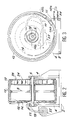
- FIG. 1 a perspective view of a winder-unwinder according to the invention. It consists of a fixed support 2 comprising for example four fixing holes making it possible to connect it by screws to a fixed station or to a mobile station.
- the support 2 is provided with two flanges 4 supporting an axis of rotation 6 on which a drum 8 is mounted to rotate.
- This drum has a helical groove in which is housed a main fiber optic cable 12.
- a fiber optic cable 14, called compensation cable is housed in the inside the drum 12. It is preferably held between two flanges 16. It has one end 14b secured to a fixed cylindrical core 18.
- this end of the compensation cable 14 is wound in a helix on a few turns, for example two or three, on the fixed cylindrical core 18 in order to create a lateral offset from said end of the cable 14 relative to the external flange 16.
- the purpose of this lateral offset is to facilitate the exit of the fixed end of the compensation cable 14 and its connection with another optical cable having a structure for example identical to that of the main optical fiber cable 12.
- this end 20 can be connected to the end 14b of the cable of c compensation 14 by means of a multi-way connector 22 mounted on the support 2.
- a rigid guide 17 protects the optical fiber cable 14.
- the optical compensation cable 14 is fixedly mounted on the peripheral wall of the drum 8.
- the drum 8 has an opening which allows the end 14a of the cable to be connected. compensation at the end 12b of the main fiber optic cable 12 by means of a connection box 15. In fact, the compensation cable is wound inside the drum while the main cable is wound outside this drum.
- the winder-unwinder also includes a spiral spring 24 disposed inside the drum.
- Spiral spring has an internal end mounted fixed on a hub 26 itself fixed relative to the frame 2 and an external end made integral with the drum 8.
- the spiral spring 24 is guided on either side by two flanges 28.
- a certain length of cable can be wound on the drum 8.
- the groove of the drum has six steps, it will be possible to wind on the drum 8 a corresponding length of cable six times the average drum circumference.
- the corresponding direction of winding of the cable 12 on the drum has been designated by the arrow 30 in FIG. 4a.
- the end 14a of the optical compensation cable performs a corresponding number of turns, so that the compensation cable 14 wound on the core 18 loosens.
- the spiral return spring has a behavior comparable to that of the compensation cable 14.
- the turns of this spring are loose. The tensile force on the main cable is then minimal.
- the turns of the spring 24 are tightened and the tensile force on the main cable is maximum.
- the fixed stop 34 mounted on the main cable which defines the maximum winding position of this main cable by preventing the drum from continuing to rotate until the spiral spring 24 is fully relaxed.
- spiral return spring 24 can be replaced by a servo geared motor, a crank or any other means within the reach of ordinary skill in the art.
- the minimum number Ne of turns in the wound position of the main optical cable 12 is given by the formula:
- Nd Ne + N
- the minimum value of d is imposed by the specification of the minimum acceptable radius of curvature by the compensation cable.
- the most favorable cable structure from this point of view is that of a cable obtained by direct bonding with bare fibers.
- the minimum radius of curvature for such a cable, although significantly greater than that of an optical fiber alone, remains of the same order of magnitude.
- This cable has a sufficient stiffness to avoid excessive collapse of the spiral and a very low roughness in order to facilitate the sliding of the turns.
- FIG. 5 shows a winder-unwinder according to the invention, designated by the reference 1, mounted on a fixed station 40. It can be seen that in this case the optical cable 20 connected to the multi-path connector 22 ends at the fixed station 40 while the free end 12a of the main cable 12 terminates in a mobile station 42.
- the free end 12a of the cable 12 is connected to a fixed station 44 while the mobile station 46 is connected to the multichannel connector via the optical cable 20.
- the device which has just been described applies to remote intervention in the nuclear sector, in particular in reprocessing factories and associated research laboratories.
- the winder-unwinder according to the invention must be hardened with nuclear radiation. It must be watertight and equipped with telemanipulable optical connections (multi-channel connector 22), that is to say capable of being remotely mounted and dismantled by means of a telemanipulator.
- the intermediate connection by means of a connection box 15, between the end 12b of the main optical fiber cable 12 situated on the drum and the end 14a of the compensation cable 14 is not essential.
- This connection box 15 can be eliminated if the same cable serves as both the main cable and the compensation cable. This is only possible if the characteristics necessary for the compensation function (small thickness, sufficient stiffness) do not are not are not incompatible with those required by the main cable (mechanical strength, chemical inertia).
Landscapes
- Physics & Mathematics (AREA)
- General Physics & Mathematics (AREA)
- Optics & Photonics (AREA)
- Light Guides In General And Applications Therefor (AREA)
- Storing, Repeated Paying-Out, And Re-Storing Of Elongated Articles (AREA)
- Mechanical Coupling Of Light Guides (AREA)
Applications Claiming Priority (2)
| Application Number | Priority Date | Filing Date | Title |
|---|---|---|---|
| FR8806534 | 1988-05-16 | ||
| FR8806534A FR2631323B1 (fr) | 1988-05-16 | 1988-05-16 | Enrouleur-derouleur pour cables a fibres optiques |
Publications (2)
| Publication Number | Publication Date |
|---|---|
| EP0343057A1 true EP0343057A1 (de) | 1989-11-23 |
| EP0343057B1 EP0343057B1 (de) | 1993-08-11 |
Family
ID=9366333
Family Applications (1)
| Application Number | Title | Priority Date | Filing Date |
|---|---|---|---|
| EP89401341A Expired - Lifetime EP0343057B1 (de) | 1988-05-16 | 1989-05-12 | Auf- und Abwickelvorrichtung für faseroptische Kabel |
Country Status (5)
| Country | Link |
|---|---|
| US (1) | US5022600A (de) |
| EP (1) | EP0343057B1 (de) |
| JP (1) | JPH0213577A (de) |
| DE (1) | DE68908266T2 (de) |
| FR (1) | FR2631323B1 (de) |
Cited By (7)
| Publication number | Priority date | Publication date | Assignee | Title |
|---|---|---|---|---|
| GB2245432A (en) * | 1990-06-21 | 1992-01-02 | Kabelmetal Electro Gmbh | Optical fibre cable installation |
| EP0486202A3 (en) * | 1990-11-13 | 1992-07-08 | Hughes Aircraft Company | Base layer for an optical fiber wound pack |
| EP0509384A3 (en) * | 1991-04-10 | 1993-05-12 | Sumitomo Electric Industries, Limited | Transmission cable termination device and method for winding and unwinding cable therefrom |
| FR2714167A1 (fr) * | 1993-12-22 | 1995-06-23 | Aerospatiale | Dispositif de reprise d'efforts, notamment pour engin filoguide. |
| EP1944635A2 (de) | 2007-01-13 | 2008-07-16 | Furukawa Electric North America Inc. (a Delaware Corporation) | An einer Wand montierbare Glasfaser- und Kabelverwaltungsvorrichtung |
| US7546018B2 (en) | 2007-01-13 | 2009-06-09 | Ofs Fitel, Llc | Fiber optic cabling for multi-dwelling unit (MDU) and commercial building deployments |
| EP2410365A1 (de) * | 2010-07-20 | 2012-01-25 | OFS Fitel, LLC | Werkzeug zum Führen einer optischen Faser oder eines Kabels zu einer Wohneinheit auf Kundengelände |
Families Citing this family (31)
| Publication number | Priority date | Publication date | Assignee | Title |
|---|---|---|---|---|
| US5230481A (en) * | 1990-06-04 | 1993-07-27 | Preco New Products Corp. | Cord take-up device |
| US5186406A (en) * | 1991-07-22 | 1993-02-16 | Grumman Aerospace Corporation | Spring actuated take-up reel for removing cable slack |
| JPH0964558A (ja) * | 1995-08-22 | 1997-03-07 | Fujitsu Ltd | 光部品モジュール及びそれを有するプリント板パッケージ並びに光ファイバの余長処理方法 |
| USRE38211E1 (en) | 1996-02-12 | 2003-08-12 | Peterson Edwin R | Uni-directional cord take-up device |
| USD399126S (en) | 1996-04-23 | 1998-10-06 | W. L. Gore & Associates, Inc. | Retractable coaxial cable reel |
| US5671833A (en) * | 1996-04-23 | 1997-09-30 | W.L. Gore & Associates, Inc. | Retractable coaxial cable device |
| JP2000009943A (ja) * | 1998-06-17 | 2000-01-14 | Fujitsu Ltd | 光伝送装置 |
| TW475796U (en) * | 2000-07-14 | 2002-02-01 | Sheng-Shing Liau | Reeling box structure capable of decreasing the friction of wire paths |
| US6726140B2 (en) * | 2001-01-05 | 2004-04-27 | Westinghouse Electric Company Llc | Take-up reel for flexible elongated members |
| US6520487B2 (en) * | 2001-01-16 | 2003-02-18 | Delaware Capital Formation, Inc. | Mounting bracket assembly for tensioning of electrified tape |
| DE20113168U1 (de) * | 2001-07-26 | 2002-08-29 | Ernst & Engbring GmbH & Co. KG, 45739 Oer-Erkenschwick | Flachkabel und Kabelwickel |
| NO317652B1 (no) * | 2002-05-03 | 2004-11-29 | Nexans | Oppkveilingsramme for kabel med optiske fibre |
| TW563996U (en) * | 2003-02-18 | 2003-11-21 | Guo-Yang Wei | Wire collecting device with multiple co-axial wheels |
| US6964509B2 (en) * | 2003-12-16 | 2005-11-15 | 3M Innovative Properties Company | Task lighting system |
| WO2007149601A2 (en) * | 2006-02-01 | 2007-12-27 | The General Hospital Corporation | Apparatus for controlling at least one of at least two sections of at least one fiber |
| SG144814A1 (en) * | 2007-01-13 | 2008-08-28 | Furukawa Electric North Am Inc | Fiber optic cabling for multi-dwelling unit (mdu) and commerical buliding deployments |
| JP5188230B2 (ja) * | 2007-03-27 | 2013-04-24 | フルカワ エレクトリック ノース アメリカ インコーポレーテッド | 壁面設置可能な光ファイバおよびケーブル処理装置 |
| US7748660B2 (en) * | 2007-06-22 | 2010-07-06 | Ofs Fitel, Llc | Fiber optic rapid spooling tool |
| US7876805B2 (en) * | 2009-06-18 | 2011-01-25 | Valentin P Gapontsev | Dynamic compensator for controlling stresses on fiber in fiber optic cables |
| US8474742B2 (en) * | 2009-07-30 | 2013-07-02 | Adc Telecommunications, Inc. | Spool for telecommunications cable and method |
| US8238707B2 (en) * | 2009-07-30 | 2012-08-07 | Adc Telecommunications, Inc. | Locking spool for telecommunications cable and method |
| WO2012012357A1 (en) * | 2010-07-20 | 2012-01-26 | Ofs Fitel, Llc | Optical fiber installation at customer premises |
| US8720810B2 (en) | 2011-02-11 | 2014-05-13 | Adc Telecommunications, Inc. | Spool for telecommunications cable and method |
| JP5867716B2 (ja) * | 2012-02-27 | 2016-02-24 | 戸田建設株式会社 | 光ファイバケーブル巻回ドラム及びそれを用いた通信システム |
| WO2013165899A1 (en) | 2012-04-30 | 2013-11-07 | Adc Telecommunications, Inc. | Cable payout cassette with single layer cable storage area |
| EP2845281A4 (de) | 2012-04-30 | 2015-12-23 | Adc Telecommunications Inc | Kabelaufnahmespule mit mittigem einzug |
| US9126802B2 (en) | 2012-04-30 | 2015-09-08 | Adc Telecommunications, Inc. | Payout spool with automatic cable disconnect/reconnect |
| US9722407B2 (en) | 2012-04-30 | 2017-08-01 | Commscope Technologies Llc | Guided cable storage assembly with switchbacks |
| DE202019101862U1 (de) * | 2019-04-01 | 2019-04-08 | Igus Gmbh | Kompakte Wickelvorrichtung für eine flexible Leitung |
| US12580375B2 (en) * | 2023-03-02 | 2026-03-17 | V. Roland Smith | Retractable cable reel for torsion-sensitive cable |
| DE102024119075A1 (de) * | 2024-07-04 | 2026-01-08 | Audi Aktiengesellschaft | Verbindungsvorrichtung, Ladevorrichtung und Fahrzeug |
Citations (7)
| Publication number | Priority date | Publication date | Assignee | Title |
|---|---|---|---|---|
| DE2810023A1 (de) * | 1977-09-26 | 1979-04-12 | Fuso Light Alloys Co Ltd | Leitungsschnurwickelvorrichtung |
| DE7936831U1 (de) * | 1979-11-19 | 1980-07-17 | Bosch-Siemens Hausgeraete Gmbh, 7000 Stuttgart | Elektrisches Haushaltgerät |
| DE8633663U1 (de) * | 1986-12-17 | 1987-02-26 | L. & C. Steinmüller GmbH, 5270 Gummersbach | Stromversorgungseinrichtung für eine fernbediente Arbeitsmaschine |
| EP0216582A2 (de) * | 1985-09-23 | 1987-04-01 | Westinghouse Electric Corporation | Vorrichtung zum Auf- und Abwickeln eines Kabels |
| US4657140A (en) * | 1985-12-18 | 1987-04-14 | The United States Of America As Represented By The Secretary Of The Air Force | Fiber optic cable storage device |
| US4657165A (en) * | 1985-09-30 | 1987-04-14 | Giroux D William | Mechanical means for preventing the twisting of a fiber optic cable while temporarily storing the same |
| DE8801683U1 (de) * | 1988-02-10 | 1988-03-24 | kabelmetal electro GmbH, 3000 Hannover | Spule zur Aufnahme einer Bandleitung mit Lichtwellenleitern |
Family Cites Families (11)
| Publication number | Priority date | Publication date | Assignee | Title |
|---|---|---|---|---|
| US1446410A (en) * | 1922-03-31 | 1923-02-20 | Bennett Sandy Boyd | Winding reel |
| US1868409A (en) * | 1931-05-26 | 1932-07-19 | Clarence C Crispen | Spring retrieving reel |
| US2438515A (en) * | 1945-10-09 | 1948-03-30 | Marvin F Mohler | Plug and jack box switching unit |
| NL68475C (de) * | 1946-05-02 | |||
| US3061234A (en) * | 1960-05-23 | 1962-10-30 | Morey Corp | Retractable conductor cord reel assembly |
| US3144218A (en) * | 1961-06-26 | 1964-08-11 | Gen Dynamics Corp | Transmission cable storing and positioning mechanism |
| US3409246A (en) * | 1966-10-31 | 1968-11-05 | Whirlpool Co | Cord reel apparatus |
| US3705962A (en) * | 1971-06-02 | 1972-12-12 | Lionel W Banister | Electrical cord retracting mechanism |
| US4010913A (en) * | 1971-10-01 | 1977-03-08 | Ametek, Inc. | Retriever reel |
| GB1590160A (en) * | 1978-05-02 | 1981-05-28 | Standard Telephones Cables Ltd | Electrical cables |
| DE3438749A1 (de) * | 1984-10-23 | 1986-04-24 | Anton Piller GmbH & Co KG, 3360 Osterode | Kabeltrommel mit elektromotorischem antrieb |
-
1988
- 1988-05-16 FR FR8806534A patent/FR2631323B1/fr not_active Expired - Lifetime
-
1989
- 1989-05-12 DE DE89401341T patent/DE68908266T2/de not_active Expired - Fee Related
- 1989-05-12 EP EP89401341A patent/EP0343057B1/de not_active Expired - Lifetime
- 1989-05-15 JP JP1121292A patent/JPH0213577A/ja active Pending
-
1990
- 1990-08-20 US US07/569,519 patent/US5022600A/en not_active Expired - Fee Related
Patent Citations (7)
| Publication number | Priority date | Publication date | Assignee | Title |
|---|---|---|---|---|
| DE2810023A1 (de) * | 1977-09-26 | 1979-04-12 | Fuso Light Alloys Co Ltd | Leitungsschnurwickelvorrichtung |
| DE7936831U1 (de) * | 1979-11-19 | 1980-07-17 | Bosch-Siemens Hausgeraete Gmbh, 7000 Stuttgart | Elektrisches Haushaltgerät |
| EP0216582A2 (de) * | 1985-09-23 | 1987-04-01 | Westinghouse Electric Corporation | Vorrichtung zum Auf- und Abwickeln eines Kabels |
| US4657165A (en) * | 1985-09-30 | 1987-04-14 | Giroux D William | Mechanical means for preventing the twisting of a fiber optic cable while temporarily storing the same |
| US4657140A (en) * | 1985-12-18 | 1987-04-14 | The United States Of America As Represented By The Secretary Of The Air Force | Fiber optic cable storage device |
| DE8633663U1 (de) * | 1986-12-17 | 1987-02-26 | L. & C. Steinmüller GmbH, 5270 Gummersbach | Stromversorgungseinrichtung für eine fernbediente Arbeitsmaschine |
| DE8801683U1 (de) * | 1988-02-10 | 1988-03-24 | kabelmetal electro GmbH, 3000 Hannover | Spule zur Aufnahme einer Bandleitung mit Lichtwellenleitern |
Cited By (20)
| Publication number | Priority date | Publication date | Assignee | Title |
|---|---|---|---|---|
| GB2245432A (en) * | 1990-06-21 | 1992-01-02 | Kabelmetal Electro Gmbh | Optical fibre cable installation |
| GB2245432B (en) * | 1990-06-21 | 1994-09-14 | Kabelmetal Electro Gmbh | Optical fibre cable installation |
| EP0486202A3 (en) * | 1990-11-13 | 1992-07-08 | Hughes Aircraft Company | Base layer for an optical fiber wound pack |
| EP0509384A3 (en) * | 1991-04-10 | 1993-05-12 | Sumitomo Electric Industries, Limited | Transmission cable termination device and method for winding and unwinding cable therefrom |
| US5332165A (en) * | 1991-04-10 | 1994-07-26 | Sumitomo Electric Industries, Ltd. | Transmission cable termination box, and transmission cable installation and recovering method |
| AU652436B2 (en) * | 1991-04-10 | 1994-08-25 | Nippon Telegraph & Telephone Corporation | Transmission cable termination box, and transmission cable installing and recovering method |
| AU661931B2 (en) * | 1991-04-10 | 1995-08-10 | Nippon Telegraph & Telephone Corporation | A method of unwinding a transmission cable stored on a stationary winding barrel |
| FR2714167A1 (fr) * | 1993-12-22 | 1995-06-23 | Aerospatiale | Dispositif de reprise d'efforts, notamment pour engin filoguide. |
| EP0660072A1 (de) * | 1993-12-22 | 1995-06-28 | AEROSPATIALE Société Nationale Industrielle | Kraftbegrenzungsvorrichtung, insbesondere für eine Rakete mit Lenkdrähten |
| EP1944635A3 (de) * | 2007-01-13 | 2008-10-08 | Furukawa Electric North America Inc. (a Delaware Corporation) | An einer Wand montierbare Glasfaser- und Kabelverwaltungsvorrichtung |
| EP1944635A2 (de) | 2007-01-13 | 2008-07-16 | Furukawa Electric North America Inc. (a Delaware Corporation) | An einer Wand montierbare Glasfaser- und Kabelverwaltungsvorrichtung |
| US7522806B2 (en) | 2007-01-13 | 2009-04-21 | Ofs Fitel, Llc | Fiber optic cable distribution box |
| US7546018B2 (en) | 2007-01-13 | 2009-06-09 | Ofs Fitel, Llc | Fiber optic cabling for multi-dwelling unit (MDU) and commercial building deployments |
| EP2256532A1 (de) * | 2007-01-13 | 2010-12-01 | Furukawa Electric North America Inc. (a Delaware Corporation) | Glasfaserverkabelung für Multi-Dwelling-Einheiten und Geschäftsgebäude |
| USRE45153E1 (en) | 2007-01-13 | 2014-09-23 | Adc Telecommunications, Inc. | Fiber optic cable distribution box |
| USRE46255E1 (en) | 2007-01-13 | 2016-12-27 | Commscope Technologies Llc | Fiber optic cable distribution box |
| USRE48063E1 (en) | 2007-01-13 | 2020-06-23 | Commscope Technologies Llc | Fiber optic cable distribution box |
| USRE49385E1 (en) | 2007-01-13 | 2023-01-24 | Commscope Technologies Llc | Fiber optic cable distribution box |
| EP2410365A1 (de) * | 2010-07-20 | 2012-01-25 | OFS Fitel, LLC | Werkzeug zum Führen einer optischen Faser oder eines Kabels zu einer Wohneinheit auf Kundengelände |
| US8792766B2 (en) | 2010-07-20 | 2014-07-29 | Ofs Fitel, Llc | Tool for routing an optical fiber or cable at a living unit of customer premises |
Also Published As
| Publication number | Publication date |
|---|---|
| US5022600A (en) | 1991-06-11 |
| EP0343057B1 (de) | 1993-08-11 |
| DE68908266T2 (de) | 1994-02-17 |
| FR2631323B1 (fr) | 1991-08-30 |
| FR2631323A1 (fr) | 1989-11-17 |
| JPH0213577A (ja) | 1990-01-17 |
| DE68908266D1 (de) | 1993-09-16 |
Similar Documents
| Publication | Publication Date | Title |
|---|---|---|
| EP0343057B1 (de) | Auf- und Abwickelvorrichtung für faseroptische Kabel | |
| EP0538164B1 (de) | Verteilergestell für optische Kabel hoher Kapazität | |
| US6915058B2 (en) | Retractable optical fiber assembly | |
| US8720810B2 (en) | Spool for telecommunications cable and method | |
| US20100021122A1 (en) | Retractable module for patch cords | |
| EP1581830A1 (de) | Spule zur aufbewahrung mit vorrichtung zum abrollen von optischen kabeln | |
| US20160116698A1 (en) | Payout spool with automatic cable disconnect/reconnect | |
| FR2686934A1 (fr) | Dispositif d'enroulement de cordon de suspension de store. | |
| US10302889B2 (en) | Gimbal transmission cable management | |
| JPS63291008A (ja) | 光ファイバの予備長さ部分用の貯蔵装置 | |
| EP0389360B1 (de) | Spule mit einer sehr langen optischen Glasfaser für eine mit einem Draht gesteuerte Rakete | |
| BR112012022795B1 (pt) | dispositivo giratório e método para habilitar uma conexão operacional contínua | |
| US20140299704A1 (en) | Retractable cord reel | |
| EP1239316A2 (de) | Vorratsrolle für optische Faser | |
| FR2652572A1 (fr) | Procede d'enroulement en double d'un cable ou analogue sur la surface externe d'un touret. | |
| FR2512287A1 (fr) | Dispositif destine a assurer le bobinage et le debobinage des cables electriques en exploitation | |
| FR2515363A1 (fr) | Dispositif permettant de compenser les variations de longueur d'au moins une fibre optique gainee, disposee dans une enveloppe | |
| FR2575874A1 (fr) | Dispositif enrouleur et derouleur d'un cable dont une extremite assure un contact electrique avec une installation fixe | |
| EP0100124A1 (de) | Optisches Abbildungssystem für einen Zielsuchkopf | |
| FR2561788A1 (fr) | Cassettes pour fibres optiques et boite de raccordement utilisant de telles cassettes | |
| US20260029605A1 (en) | Optical fiber ribbon storage device for use in splice closures | |
| JPS6193410A (ja) | 光フアイバ−ケ−ブル用ハンガ− | |
| WO1993002009A1 (fr) | Dispositif enrouleur-derouleur de lien sans discontinuite de lien | |
| JPS6318002Y2 (de) | ||
| FR2564989A1 (fr) | Dispositif de rangement de cables a fibres optiques |
Legal Events
| Date | Code | Title | Description |
|---|---|---|---|
| PUAI | Public reference made under article 153(3) epc to a published international application that has entered the european phase |
Free format text: ORIGINAL CODE: 0009012 |
|
| AK | Designated contracting states |
Kind code of ref document: A1 Designated state(s): BE DE GB SE |
|
| 17P | Request for examination filed |
Effective date: 19900507 |
|
| 17Q | First examination report despatched |
Effective date: 19920210 |
|
| GRAA | (expected) grant |
Free format text: ORIGINAL CODE: 0009210 |
|
| AK | Designated contracting states |
Kind code of ref document: B1 Designated state(s): BE DE GB SE |
|
| RIN1 | Information on inventor provided before grant (corrected) |
Inventor name: LORDET, JACQUES Inventor name: BLANC, FLOREAL |
|
| REF | Corresponds to: |
Ref document number: 68908266 Country of ref document: DE Date of ref document: 19930916 |
|
| GBT | Gb: translation of ep patent filed (gb section 77(6)(a)/1977) |
Effective date: 19931020 |
|
| PLBE | No opposition filed within time limit |
Free format text: ORIGINAL CODE: 0009261 |
|
| STAA | Information on the status of an ep patent application or granted ep patent |
Free format text: STATUS: NO OPPOSITION FILED WITHIN TIME LIMIT |
|
| 26N | No opposition filed | ||
| EAL | Se: european patent in force in sweden |
Ref document number: 89401341.6 |
|
| PGFP | Annual fee paid to national office [announced via postgrant information from national office to epo] |
Ref country code: SE Payment date: 19950425 Year of fee payment: 7 |
|
| PGFP | Annual fee paid to national office [announced via postgrant information from national office to epo] |
Ref country code: GB Payment date: 19950501 Year of fee payment: 7 |
|
| PGFP | Annual fee paid to national office [announced via postgrant information from national office to epo] |
Ref country code: DE Payment date: 19950504 Year of fee payment: 7 |
|
| PGFP | Annual fee paid to national office [announced via postgrant information from national office to epo] |
Ref country code: BE Payment date: 19950505 Year of fee payment: 7 |
|
| PG25 | Lapsed in a contracting state [announced via postgrant information from national office to epo] |
Ref country code: GB Effective date: 19960512 |
|
| PG25 | Lapsed in a contracting state [announced via postgrant information from national office to epo] |
Ref country code: SE Effective date: 19960513 |
|
| PG25 | Lapsed in a contracting state [announced via postgrant information from national office to epo] |
Ref country code: BE Effective date: 19960531 |
|
| BERE | Be: lapsed |
Owner name: COMMISSARIAT A L' ENERGIE ATOMIQUE Effective date: 19960531 |
|
| GBPC | Gb: european patent ceased through non-payment of renewal fee |
Effective date: 19960512 |
|
| PG25 | Lapsed in a contracting state [announced via postgrant information from national office to epo] |
Ref country code: DE Effective date: 19970201 |
|
| EUG | Se: european patent has lapsed |
Ref document number: 89401341.6 |