EP0343099B1 - Transformateur d'intensité enroulé - Google Patents
Transformateur d'intensité enroulé Download PDFInfo
- Publication number
- EP0343099B1 EP0343099B1 EP89730117A EP89730117A EP0343099B1 EP 0343099 B1 EP0343099 B1 EP 0343099B1 EP 89730117 A EP89730117 A EP 89730117A EP 89730117 A EP89730117 A EP 89730117A EP 0343099 B1 EP0343099 B1 EP 0343099B1
- Authority
- EP
- European Patent Office
- Prior art keywords
- capacitor
- current transformer
- conductive
- iron core
- ring
- Prior art date
- Legal status (The legal status is an assumption and is not a legal conclusion. Google has not performed a legal analysis and makes no representation as to the accuracy of the status listed.)
- Expired - Lifetime
Links
Images

Classifications
-
- H—ELECTRICITY
- H01—ELECTRIC ELEMENTS
- H01F—MAGNETS; INDUCTANCES; TRANSFORMERS; SELECTION OF MATERIALS FOR THEIR MAGNETIC PROPERTIES
- H01F38/00—Adaptations of transformers or inductances for specific applications or functions
- H01F38/20—Instruments transformers
- H01F38/22—Instruments transformers for single phase AC
- H01F38/28—Current transformers
- H01F38/30—Constructions
-
- H—ELECTRICITY
- H01—ELECTRIC ELEMENTS
- H01F—MAGNETS; INDUCTANCES; TRANSFORMERS; SELECTION OF MATERIALS FOR THEIR MAGNETIC PROPERTIES
- H01F38/00—Adaptations of transformers or inductances for specific applications or functions
- H01F38/20—Instruments transformers
- H01F38/22—Instruments transformers for single phase AC
- H01F38/28—Current transformers
- H01F38/30—Constructions
- H01F2038/305—Constructions with toroidal magnetic core
Definitions
- the invention relates to a winding current transformer with at least one ring-shaped iron core carrying a secondary winding, with a primary winding with a plurality of turns passing through the window of the iron core with a conductive sheathing and with a ring capacitor lying in the window of the iron core against the secondary winding and having a continuous longitudinal slot, the two receptacles forming the electrodes of the ring capacitor and located on different sides of the ring capacitor are provided with electrical connection lines for secondary connection terminals.
- a winding current transformer of this type is known from German utility model 84 26 556.
- the ratio of the high-voltage capacitor to the low-voltage capacitor in the case of an unchangeable high-voltage capacitor is determined by the capacitance of the ring capacitor. If the divider ratio is to be changed, this is possible in the known winding current transformer in that an external capacitor is connected to the secondary connection terminals, as a result of which the capacitance of the undervoltage capacitor is increased as a result of parallel connection and the divider ratio is thereby changed.
- Such an adjustment of the division ratio to the respective needs is, however, quite complex.
- conductive, cylindrical inserts between the coverings, which extend coaxially aligned at least over part of the length of the ring capacitor and are connected to the connection terminals.
- the main advantage of the winding current transformer according to the invention is that additional capacities are formed by the conductive inserts within the area between the linings, which due to the connection of these conductive inserts with the connecting terminals represent parallel capacities to the capacitance formed by the linings of the ring capacitor.
- the division ratio of the upper to lower voltage capacitor can be adjusted according to the respective requirements without the need for an additional external capacitor.
- the coordination of the total capacitance of the undervoltage capacitor is possible in a simple manner in that the cylindrical inserts extend over such a part of the total length or over the total length of the ring capacitor that partial capacitances are formed which in total correspond to the required value of the capacitance of the undervoltage capacitor, whereby the required division ratio is achieved.
- the insert adjacent to the inner covering with the electrical connection line of the outer covering and the insert adjacent to the outer covering with the electrical connection line of the insert are advantageously in the case of the winding current transformer according to the invention inner lining connected. If more than two inserts are provided in the winding current transformer according to the invention, then further inserts are to be connected to the connecting lines in accordance with the specified scheme.
- the winding current transformer shown in FIG. 1 has a block-shaped cast resin body 1, in which, among other things, an annular iron core 2 with an applied secondary winding 3 lies.
- the window 4 of the iron core 2 is penetrated by several turns of a primary winding 5, which is brought up to the outer connecting bolts 6 and 7.
- Each turn of the primary winding 5 carries a layer of conductive or semiconducting material on an insulation, as described in detail in German Utility Model 78 12 060.
- the individual turns of the primary windings 5 are held together by means of a tensioning band 8, as a result of which the layers of conductive or semiconducting material of the individual turns come into contact with one another and additionally all layers have one and the same potential due to the metal tensioning band, so that the primary winding 5 has an outward direction has acting conductive sheath.
- a secondary terminal box 9 is held laterally, in which secondary terminals, not shown in detail, are accommodated.
- a ring capacitor 10 which contains an insulating body 11.
- the insulating body 11 or the entire ring capacitor 10 has a continuous longitudinal slot 12.
- a conductive covering 14 which ends at a distance both from the longitudinal slot 12 and from the front edges of the insulating body 1.
- a conductive coating is applied to the outer side of the insulating body 11, which is not visible here, so that the two coatings together with the insulating body 11 form a ring capacitor 10.
- the insulating body 11 which preferably consists of a winding of insulating material, there are cylindrical, conductive inserts 15 and 16, which are only indicated by dashed lines in FIG. 1 because, like the inner covering 14, they are not guided to the outer edge of the insulating body.
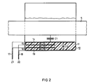
- These deposits 15 and 16 form additional capacitances with the coatings of the ring capacitor 10, as will be explained in more detail with reference to FIG. 2.
- Both the conductive coating 14 on the inside of the ring capacitor 10 and the outer coating (not visible in FIG. 1) as well as the inserts 15 and 16 are connected in a manner shown in FIG. 2 to electrical connecting lines 17 and 18 which are in the secondary terminal box 9 are performed.
- the voltage at the ring capacitor 10 forming the undervoltage capacitor of a capacitive divider can thus be tapped on the outside.
- the high-voltage capacitor of the capacitive voltage divider is formed by the conductive covering 14 and the conductive sheathing of the primary winding 5.
- FIG. 2 only the straight area passing through the core window 3 of the primary winding 5 is shown schematically; this area of the primary winding 5 is surrounded by the ring capacitor 10, so that a capacitance C1 is formed between the conductive sheath of the primary winding 5 and the inner coating 14 of the ring capacitor 10, which capacitance forms the capacitance of the high-voltage capacitor of a capacitive divider.
- the conductive inserts 15 and 16 are accommodated, which form capacitances C14, C15 and C16 with the inner layer 14 and the outer layer 19 of the ring capacitor.
- a further capacitance C2 is formed between the inner covering 14 and the outer covering 19 in the area on the right in FIG. 2.
- the conductive insert 15 of the ring capacitor 10 adjacent to the inner covering 14 is connected at point 20 to the electrical connecting line 18 of the outer covering 19, while the conductive insert 16 adjacent to the outer covering 19 is connected at 21 to the electrical connecting line 17 of the inner covering 14 in Is connected.
- a total capacitance of the ring capacitor 10 then arises between the two points 20 and 21, which results from the sum of the capacitances C14, C15, C16 and C2.
- By appropriate length dimensioning of the conductive Deposits 15 and 16 can set the value of the total capacitance of the undervoltage capacitor or ring capacitor 10.
Landscapes
- Engineering & Computer Science (AREA)
- Power Engineering (AREA)
- Transformers For Measuring Instruments (AREA)
- Details Of Television Scanning (AREA)
Claims (2)
- Transformateur d'intensité bobiné comportant au moins un noyau de fer annulaire (2), qui porte un enroulement secondaire (3), un enroulement primaire (5) dont les spires traversent la fenêtre (4) du noyau de fer (2) et qui comporte une gaine conductrice, et un condensateur annulaire (10), qui est appliqué contre l'enroulement secondaire (3), dans la fenêtre (4) du noyau de fer (2), possède une fente longitudinale continue (12) et dont deux armatures (14,19), qui constituent les électrodes du condensateur annulaire (10) et sont situées sur des faces différentes de ce condensateur, sont pourvues de conducteurs électriques de raccordement (17,18) pour des bornes de raccordement secondaires,
caractérisé par le fait qu'entre les armatures (14,19) sont disposés des inserts conducteurs cylindriques (15,16), qui s'étendent au moins sur une partie de la longueur du condensateur annulaire (10), en étant orientés coaxialement, et sont raccordés aux conducteurs de raccordement (17,18). - Transformateur d'intensité bobiné suivant la revendication 1, caractérisé par le fait que dans le cas de deux inserts, l'insert (15), qui est voisin de l'armature intérieure (14), est raccordé au conducteur de raccordement électrique de l'armature extérieure (19), et l'insert (16), qui est voisin de l'armature extérieure (19), est raccordé au conducteur de raccordement électrique (17) de l'armature intérieure (14).
Priority Applications (1)
| Application Number | Priority Date | Filing Date | Title |
|---|---|---|---|
| AT89730117T ATE85152T1 (de) | 1988-05-19 | 1989-05-10 | Wickelstromwandler. |
Applications Claiming Priority (2)
| Application Number | Priority Date | Filing Date | Title |
|---|---|---|---|
| DE8806688U | 1988-05-19 | ||
| DE8806688U DE8806688U1 (de) | 1988-05-19 | 1988-05-19 | Wickelstromwandler |
Publications (2)
| Publication Number | Publication Date |
|---|---|
| EP0343099A1 EP0343099A1 (fr) | 1989-11-23 |
| EP0343099B1 true EP0343099B1 (fr) | 1993-01-27 |
Family
ID=6824299
Family Applications (1)
| Application Number | Title | Priority Date | Filing Date |
|---|---|---|---|
| EP89730117A Expired - Lifetime EP0343099B1 (fr) | 1988-05-19 | 1989-05-10 | Transformateur d'intensité enroulé |
Country Status (3)
| Country | Link |
|---|---|
| EP (1) | EP0343099B1 (fr) |
| AT (1) | ATE85152T1 (fr) |
| DE (2) | DE8806688U1 (fr) |
Families Citing this family (3)
| Publication number | Priority date | Publication date | Assignee | Title |
|---|---|---|---|---|
| DE102013211811A1 (de) * | 2013-06-21 | 2014-12-24 | Siemens Aktiengesellschaft | Wandlereinheit, insbesondere Kombinationswandler |
| EP3371817B1 (fr) * | 2015-11-05 | 2025-08-06 | HM Power AB | Capteur de courant |
| CN108335894A (zh) * | 2018-04-08 | 2018-07-27 | 国网重庆市电力公司电力科学研究院 | 一种新型防恒定磁场电流互感器 |
Family Cites Families (4)
| Publication number | Priority date | Publication date | Assignee | Title |
|---|---|---|---|---|
| US3173114A (en) * | 1962-01-17 | 1965-03-09 | Westinghouse Electric Corp | Electrical inductive apparatus |
| US3299383A (en) * | 1965-11-04 | 1967-01-17 | Westinghouse Electric Corp | Current transformer having fluid carry passages in high voltage conductor |
| DE3166324D1 (en) * | 1981-04-28 | 1984-10-31 | Sprecher & Schuh Ag | Current transformer with annular case to be built in a metal cast high-tension switchgear installation |
| DE8426556U1 (de) * | 1984-09-05 | 1986-11-06 | Siemens AG, 1000 Berlin und 8000 München | Wickelstromwandler |
-
1988
- 1988-05-19 DE DE8806688U patent/DE8806688U1/de not_active Expired
-
1989
- 1989-05-10 AT AT89730117T patent/ATE85152T1/de not_active IP Right Cessation
- 1989-05-10 EP EP89730117A patent/EP0343099B1/fr not_active Expired - Lifetime
- 1989-05-10 DE DE8989730117T patent/DE58903381D1/de not_active Expired - Fee Related
Also Published As
| Publication number | Publication date |
|---|---|
| DE8806688U1 (de) | 1988-07-14 |
| ATE85152T1 (de) | 1993-02-15 |
| EP0343099A1 (fr) | 1989-11-23 |
| DE58903381D1 (de) | 1993-03-11 |
Similar Documents
| Publication | Publication Date | Title |
|---|---|---|
| DE2626285C2 (de) | Transformator | |
| DE3039530C2 (fr) | ||
| DE3020400A1 (de) | Transformator | |
| DE69006655T2 (de) | Generator zum Erzeugen einer elektrischen Spannung. | |
| DE2445143C2 (de) | Elektrischer Übertrager | |
| EP0343099B1 (fr) | Transformateur d'intensité enroulé | |
| DE19829505B4 (de) | Induktivität | |
| DE1297217B (de) | Roehrenwicklung fuer Transformatoren | |
| DE69831949T2 (de) | Dioden-split-hochspannungstransformator | |
| DE3882626T2 (de) | Transformator. | |
| EP0510149B1 (fr) | Armature de bobine, en particulier pour petits transformateurs et transformateurs de securite | |
| DE3414366A1 (de) | Metallgekapselte, gasisolierte schaltanlage | |
| DE3238250C2 (fr) | ||
| EP0082966B1 (fr) | Tranformateur de lignes pour récepteurs de télévision | |
| DE69603993T2 (de) | Transformator, insbesondere für Energiewandler, und Resonanzenergiewandler mit einem solchen Transformator | |
| DE1638885A1 (de) | Hochspannungswicklung | |
| DE2024522A1 (de) | Transformator, Meßwandler oder der gletchen | |
| AT391769B (de) | Wickelstromwandler | |
| DE1073614B (de) | Transformator für hohe Spannung mit Schirmanordnung für die Potentialsteuerung | |
| DE2754221A1 (de) | Hochspannungsspule fuer einen hochspannungstransformator | |
| DE2420451C2 (de) | Vorrichtung zur Spannungsverdoppelung | |
| DE976080C (de) | Kombinierter Strom- und Spannungswandler | |
| DE2554142A1 (de) | Anordnung mit induktiven spannungswandlern | |
| DE2505761A1 (de) | Magnetkreis sowie strommesser und differenztransformator damit | |
| DE2325443B2 (de) | Spannungswandler für eine mehrere Leiter führende Hochspannungsschaltanlage |
Legal Events
| Date | Code | Title | Description |
|---|---|---|---|
| PUAI | Public reference made under article 153(3) epc to a published international application that has entered the european phase |
Free format text: ORIGINAL CODE: 0009012 |
|
| AK | Designated contracting states |
Kind code of ref document: A1 Designated state(s): AT BE CH DE FR IT LI |
|
| 17P | Request for examination filed |
Effective date: 19900517 |
|
| 17Q | First examination report despatched |
Effective date: 19920415 |
|
| GRAA | (expected) grant |
Free format text: ORIGINAL CODE: 0009210 |
|
| AK | Designated contracting states |
Kind code of ref document: B1 Designated state(s): AT BE CH DE FR IT LI |
|
| REF | Corresponds to: |
Ref document number: 85152 Country of ref document: AT Date of ref document: 19930215 Kind code of ref document: T |
|
| REF | Corresponds to: |
Ref document number: 58903381 Country of ref document: DE Date of ref document: 19930311 |
|
| ET | Fr: translation filed | ||
| ITF | It: translation for a ep patent filed | ||
| PLBE | No opposition filed within time limit |
Free format text: ORIGINAL CODE: 0009261 |
|
| STAA | Information on the status of an ep patent application or granted ep patent |
Free format text: STATUS: NO OPPOSITION FILED WITHIN TIME LIMIT |
|
| 26N | No opposition filed | ||
| PGFP | Annual fee paid to national office [announced via postgrant information from national office to epo] |
Ref country code: DE Payment date: 19940719 Year of fee payment: 6 |
|
| PGFP | Annual fee paid to national office [announced via postgrant information from national office to epo] |
Ref country code: CH Payment date: 19940818 Year of fee payment: 6 |
|
| PGFP | Annual fee paid to national office [announced via postgrant information from national office to epo] |
Ref country code: AT Payment date: 19950421 Year of fee payment: 7 |
|
| PGFP | Annual fee paid to national office [announced via postgrant information from national office to epo] |
Ref country code: BE Payment date: 19950511 Year of fee payment: 7 |
|
| PGFP | Annual fee paid to national office [announced via postgrant information from national office to epo] |
Ref country code: FR Payment date: 19950522 Year of fee payment: 7 |
|
| PG25 | Lapsed in a contracting state [announced via postgrant information from national office to epo] |
Ref country code: LI Effective date: 19950531 Ref country code: CH Effective date: 19950531 |
|
| REG | Reference to a national code |
Ref country code: CH Ref legal event code: PL |
|
| PG25 | Lapsed in a contracting state [announced via postgrant information from national office to epo] |
Ref country code: DE Effective date: 19960201 |
|
| PG25 | Lapsed in a contracting state [announced via postgrant information from national office to epo] |
Ref country code: AT Effective date: 19960510 |
|
| PG25 | Lapsed in a contracting state [announced via postgrant information from national office to epo] |
Ref country code: BE Effective date: 19960531 |
|
| BERE | Be: lapsed |
Owner name: SIEMENS A.G. Effective date: 19960531 |
|
| PG25 | Lapsed in a contracting state [announced via postgrant information from national office to epo] |
Ref country code: FR Effective date: 19970131 |
|
| REG | Reference to a national code |
Ref country code: FR Ref legal event code: ST |
|
| PG25 | Lapsed in a contracting state [announced via postgrant information from national office to epo] |
Ref country code: IT Free format text: LAPSE BECAUSE OF NON-PAYMENT OF DUE FEES;WARNING: LAPSES OF ITALIAN PATENTS WITH EFFECTIVE DATE BEFORE 2007 MAY HAVE OCCURRED AT ANY TIME BEFORE 2007. THE CORRECT EFFECTIVE DATE MAY BE DIFFERENT FROM THE ONE RECORDED. Effective date: 20050510 |