EP0343122A1 - Cellule électrolytique - Google Patents
Cellule électrolytique Download PDFInfo
- Publication number
- EP0343122A1 EP0343122A1 EP89830204A EP89830204A EP0343122A1 EP 0343122 A1 EP0343122 A1 EP 0343122A1 EP 89830204 A EP89830204 A EP 89830204A EP 89830204 A EP89830204 A EP 89830204A EP 0343122 A1 EP0343122 A1 EP 0343122A1
- Authority
- EP
- European Patent Office
- Prior art keywords
- fluid
- window
- electrolytic cell
- anode
- evolved
- Prior art date
- Legal status (The legal status is an assumption and is not a legal conclusion. Google has not performed a legal analysis and makes no representation as to the accuracy of the status listed.)
- Granted
Links
- 239000012530 fluid Substances 0.000 claims abstract description 59
- 239000007789 gas Substances 0.000 claims abstract description 37
- 239000011347 resin Substances 0.000 claims description 15
- 229920005989 resin Polymers 0.000 claims description 15
- YCKRFDGAMUMZLT-UHFFFAOYSA-N Fluorine atom Chemical compound [F] YCKRFDGAMUMZLT-UHFFFAOYSA-N 0.000 claims description 14
- 229910052731 fluorine Inorganic materials 0.000 claims description 14
- 239000011737 fluorine Substances 0.000 claims description 14
- 230000002209 hydrophobic effect Effects 0.000 claims description 5
- 229910010293 ceramic material Inorganic materials 0.000 claims 4
- 238000005868 electrolysis reaction Methods 0.000 abstract description 9
- 239000003792 electrolyte Substances 0.000 description 16
- 239000003014 ion exchange membrane Substances 0.000 description 15
- PXHVJJICTQNCMI-UHFFFAOYSA-N Nickel Chemical compound [Ni] PXHVJJICTQNCMI-UHFFFAOYSA-N 0.000 description 14
- 238000011282 treatment Methods 0.000 description 13
- 238000000034 method Methods 0.000 description 11
- NBIIXXVUZAFLBC-UHFFFAOYSA-N Phosphoric acid Chemical compound OP(O)(O)=O NBIIXXVUZAFLBC-UHFFFAOYSA-N 0.000 description 10
- HEMHJVSKTPXQMS-UHFFFAOYSA-M Sodium hydroxide Chemical compound [OH-].[Na+] HEMHJVSKTPXQMS-UHFFFAOYSA-M 0.000 description 9
- CBENFWSGALASAD-UHFFFAOYSA-N Ozone Chemical compound [O-][O+]=O CBENFWSGALASAD-UHFFFAOYSA-N 0.000 description 8
- RTAQQCXQSZGOHL-UHFFFAOYSA-N Titanium Chemical compound [Ti] RTAQQCXQSZGOHL-UHFFFAOYSA-N 0.000 description 8
- 239000010936 titanium Substances 0.000 description 8
- XLYOFNOQVPJJNP-UHFFFAOYSA-N water Substances O XLYOFNOQVPJJNP-UHFFFAOYSA-N 0.000 description 8
- 239000007864 aqueous solution Substances 0.000 description 7
- 229910052719 titanium Inorganic materials 0.000 description 7
- FAPWRFPIFSIZLT-UHFFFAOYSA-M Sodium chloride Chemical compound [Na+].[Cl-] FAPWRFPIFSIZLT-UHFFFAOYSA-M 0.000 description 6
- 238000011109 contamination Methods 0.000 description 6
- YADSGOSSYOOKMP-UHFFFAOYSA-N dioxolead Chemical compound O=[Pb]=O YADSGOSSYOOKMP-UHFFFAOYSA-N 0.000 description 6
- 229910052759 nickel Inorganic materials 0.000 description 6
- KZBUYRJDOAKODT-UHFFFAOYSA-N Chlorine Chemical compound ClCl KZBUYRJDOAKODT-UHFFFAOYSA-N 0.000 description 5
- UFHFLCQGNIYNRP-UHFFFAOYSA-N Hydrogen Chemical compound [H][H] UFHFLCQGNIYNRP-UHFFFAOYSA-N 0.000 description 5
- 229910000147 aluminium phosphate Inorganic materials 0.000 description 5
- QVGXLLKOCUKJST-UHFFFAOYSA-N atomic oxygen Chemical compound [O] QVGXLLKOCUKJST-UHFFFAOYSA-N 0.000 description 5
- 239000012528 membrane Substances 0.000 description 5
- 239000001301 oxygen Substances 0.000 description 5
- 229910052760 oxygen Inorganic materials 0.000 description 5
- 239000000243 solution Substances 0.000 description 5
- 239000011248 coating agent Substances 0.000 description 4
- 238000000576 coating method Methods 0.000 description 4
- 238000006243 chemical reaction Methods 0.000 description 3
- 239000008246 gaseous mixture Substances 0.000 description 3
- 239000000463 material Substances 0.000 description 3
- 229920001343 polytetrafluoroethylene Polymers 0.000 description 3
- 239000004810 polytetrafluoroethylene Substances 0.000 description 3
- 239000011780 sodium chloride Substances 0.000 description 3
- ZAMOUSCENKQFHK-UHFFFAOYSA-N Chlorine atom Chemical compound [Cl] ZAMOUSCENKQFHK-UHFFFAOYSA-N 0.000 description 2
- 229920000557 Nafion® Polymers 0.000 description 2
- 239000006183 anode active material Substances 0.000 description 2
- 239000006182 cathode active material Substances 0.000 description 2
- 239000003153 chemical reaction reagent Substances 0.000 description 2
- 239000000460 chlorine Substances 0.000 description 2
- 229910052801 chlorine Inorganic materials 0.000 description 2
- 238000005260 corrosion Methods 0.000 description 2
- 230000007797 corrosion Effects 0.000 description 2
- 239000007772 electrode material Substances 0.000 description 2
- -1 polytetrafluoroethylene Polymers 0.000 description 2
- 238000005245 sintering Methods 0.000 description 2
- 239000010935 stainless steel Substances 0.000 description 2
- 229910001220 stainless steel Inorganic materials 0.000 description 2
- 238000004659 sterilization and disinfection Methods 0.000 description 2
- 239000000725 suspension Substances 0.000 description 2
- VEXZGXHMUGYJMC-UHFFFAOYSA-M Chloride anion Chemical compound [Cl-] VEXZGXHMUGYJMC-UHFFFAOYSA-M 0.000 description 1
- MYMOFIZGZYHOMD-UHFFFAOYSA-N Dioxygen Chemical compound O=O MYMOFIZGZYHOMD-UHFFFAOYSA-N 0.000 description 1
- 229920000544 Gore-Tex Polymers 0.000 description 1
- 229910001069 Ti alloy Inorganic materials 0.000 description 1
- 239000003054 catalyst Substances 0.000 description 1
- 239000000919 ceramic Substances 0.000 description 1
- 239000003795 chemical substances by application Substances 0.000 description 1
- 239000003426 co-catalyst Substances 0.000 description 1
- 239000002131 composite material Substances 0.000 description 1
- 238000010276 construction Methods 0.000 description 1
- 238000000354 decomposition reaction Methods 0.000 description 1
- 230000000249 desinfective effect Effects 0.000 description 1
- 230000006866 deterioration Effects 0.000 description 1
- 238000010790 dilution Methods 0.000 description 1
- 239000012895 dilution Substances 0.000 description 1
- 229910001882 dioxygen Inorganic materials 0.000 description 1
- 238000007772 electroless plating Methods 0.000 description 1
- 239000011521 glass Substances 0.000 description 1
- 230000005484 gravity Effects 0.000 description 1
- 238000010438 heat treatment Methods 0.000 description 1
- 239000001257 hydrogen Substances 0.000 description 1
- 229910052739 hydrogen Inorganic materials 0.000 description 1
- 230000007062 hydrolysis Effects 0.000 description 1
- 238000006460 hydrolysis reaction Methods 0.000 description 1
- 229910000464 lead oxide Inorganic materials 0.000 description 1
- 239000007788 liquid Substances 0.000 description 1
- 238000012423 maintenance Methods 0.000 description 1
- 229910052751 metal Inorganic materials 0.000 description 1
- 239000002184 metal Substances 0.000 description 1
- 150000002739 metals Chemical class 0.000 description 1
- 239000000203 mixture Substances 0.000 description 1
- 238000012986 modification Methods 0.000 description 1
- 230000004048 modification Effects 0.000 description 1
- 239000005416 organic matter Substances 0.000 description 1
- YEXPOXQUZXUXJW-UHFFFAOYSA-N oxolead Chemical compound [Pb]=O YEXPOXQUZXUXJW-UHFFFAOYSA-N 0.000 description 1
- 230000000737 periodic effect Effects 0.000 description 1
- 239000012466 permeate Substances 0.000 description 1
- 239000005518 polymer electrolyte Substances 0.000 description 1
- 239000004800 polyvinyl chloride Substances 0.000 description 1
- 239000000843 powder Substances 0.000 description 1
- 239000000047 product Substances 0.000 description 1
- 238000000746 purification Methods 0.000 description 1
- 229920006395 saturated elastomer Polymers 0.000 description 1
- 229910001415 sodium ion Inorganic materials 0.000 description 1
- 239000007787 solid Substances 0.000 description 1
- 230000001954 sterilising effect Effects 0.000 description 1
- 239000000126 substance Substances 0.000 description 1
- 239000010409 thin film Substances 0.000 description 1
- 239000002912 waste gas Substances 0.000 description 1
Images
Classifications
-
- C—CHEMISTRY; METALLURGY
- C02—TREATMENT OF WATER, WASTE WATER, SEWAGE, OR SLUDGE
- C02F—TREATMENT OF WATER, WASTE WATER, SEWAGE, OR SLUDGE
- C02F1/00—Treatment of water, waste water, or sewage
- C02F1/46—Treatment of water, waste water, or sewage by electrochemical methods
- C02F1/461—Treatment of water, waste water, or sewage by electrochemical methods by electrolysis
- C02F1/46104—Devices therefor; Their operating or servicing
-
- C—CHEMISTRY; METALLURGY
- C02—TREATMENT OF WATER, WASTE WATER, SEWAGE, OR SLUDGE
- C02F—TREATMENT OF WATER, WASTE WATER, SEWAGE, OR SLUDGE
- C02F1/00—Treatment of water, waste water, or sewage
- C02F1/46—Treatment of water, waste water, or sewage by electrochemical methods
- C02F1/461—Treatment of water, waste water, or sewage by electrochemical methods by electrolysis
- C02F1/467—Treatment of water, waste water, or sewage by electrochemical methods by electrolysis by electrochemical disinfection; by electrooxydation or by electroreduction
- C02F1/4672—Treatment of water, waste water, or sewage by electrochemical methods by electrolysis by electrochemical disinfection; by electrooxydation or by electroreduction by electrooxydation
- C02F1/4674—Treatment of water, waste water, or sewage by electrochemical methods by electrolysis by electrochemical disinfection; by electrooxydation or by electroreduction by electrooxydation with halogen or compound of halogens, e.g. chlorine, bromine
-
- C—CHEMISTRY; METALLURGY
- C02—TREATMENT OF WATER, WASTE WATER, SEWAGE, OR SLUDGE
- C02F—TREATMENT OF WATER, WASTE WATER, SEWAGE, OR SLUDGE
- C02F1/00—Treatment of water, waste water, or sewage
- C02F1/46—Treatment of water, waste water, or sewage by electrochemical methods
- C02F1/461—Treatment of water, waste water, or sewage by electrochemical methods by electrolysis
- C02F1/467—Treatment of water, waste water, or sewage by electrochemical methods by electrolysis by electrochemical disinfection; by electrooxydation or by electroreduction
- C02F1/4672—Treatment of water, waste water, or sewage by electrochemical methods by electrolysis by electrochemical disinfection; by electrooxydation or by electroreduction by electrooxydation
-
- C—CHEMISTRY; METALLURGY
- C02—TREATMENT OF WATER, WASTE WATER, SEWAGE, OR SLUDGE
- C02F—TREATMENT OF WATER, WASTE WATER, SEWAGE, OR SLUDGE
- C02F1/00—Treatment of water, waste water, or sewage
- C02F1/72—Treatment of water, waste water, or sewage by oxidation
- C02F1/76—Treatment of water, waste water, or sewage by oxidation with halogens or compounds of halogens
- C02F1/763—Devices for the addition of such compounds in gaseous form
-
- C—CHEMISTRY; METALLURGY
- C02—TREATMENT OF WATER, WASTE WATER, SEWAGE, OR SLUDGE
- C02F—TREATMENT OF WATER, WASTE WATER, SEWAGE, OR SLUDGE
- C02F1/00—Treatment of water, waste water, or sewage
- C02F1/46—Treatment of water, waste water, or sewage by electrochemical methods
- C02F1/461—Treatment of water, waste water, or sewage by electrochemical methods by electrolysis
- C02F1/46104—Devices therefor; Their operating or servicing
- C02F1/46109—Electrodes
- C02F2001/46133—Electrodes characterised by the material
- C02F2001/46138—Electrodes comprising a substrate and a coating
- C02F2001/46142—Catalytic coating
-
- C—CHEMISTRY; METALLURGY
- C02—TREATMENT OF WATER, WASTE WATER, SEWAGE, OR SLUDGE
- C02F—TREATMENT OF WATER, WASTE WATER, SEWAGE, OR SLUDGE
- C02F2201/00—Apparatus for treatment of water, waste water or sewage
- C02F2201/46—Apparatus for electrochemical processes
- C02F2201/461—Electrolysis apparatus
- C02F2201/46105—Details relating to the electrolytic devices
- C02F2201/46115—Electrolytic cell with membranes or diaphragms
-
- C—CHEMISTRY; METALLURGY
- C02—TREATMENT OF WATER, WASTE WATER, SEWAGE, OR SLUDGE
- C02F—TREATMENT OF WATER, WASTE WATER, SEWAGE, OR SLUDGE
- C02F2201/00—Apparatus for treatment of water, waste water or sewage
- C02F2201/46—Apparatus for electrochemical processes
- C02F2201/461—Electrolysis apparatus
- C02F2201/46105—Details relating to the electrolytic devices
- C02F2201/46195—Cells containing solid electrolyte
Definitions
- the present invention relates to an electrolytic cell used to treat fluids with gases that are evolved by electrolysis.
- gases to be injected are introduced from an electrolytic cell through a filter and piping into a treatment vessel.
- pressure loss occurs within the piping or filter.
- a pressurizing pump or other means which increases the complexity of the equipment is necessary.
- a method has been adopted in which the gases are preliminarily dissolved in water or another media and the resulting solution is mixed with the fluid of interest to cause a reaction. This method is advantageous in that a uniform reaction occurs and the gases evolved by hydrolysis are almost completely utilized.
- the volume of the fluid to be treated increases. This in turn necessitates post-treatments including reconcentration of the treated fluid.
- the present invention solves the two prior art problems, simultaneously. Namely, the present invention solves the problems of an increase in the volume of the fluid being treated and contamination thereof.
- An object, therefore, of the present invention is to provide an electrolytic cell in which gases evolved by electrolysis are brought into direct contact with the fluid to be treated thereby allowing the fluid to be treated easily and efficiently.
- an electrolytic cell composed of an anode compartment separated from a cathode compartment by a diaphragm.
- the electrolytic cell has a gas-permeable and liquid-impermeable window formed in said anode and/or cathode compartment in such a way that the gas evolved in said anode or cathode compartment or the gases evolved in these two compartments are allowed to pass through said window to make contact with a fluid to be treated in the outside of said electrolytic cell, thereby treating said fluid.
- the gas or gases evolved by electrolysis are allowed to pass through a gas-permeable and liquid-impermeable window to make contact with a fluid to be treated in the outside of the cell, thereby treating said effluent.
- This arrangement obviates the prior art need to use piping to achieve contact between the evolved gases and the fluid to be treated, thereby eliminating pressure loss that would otherwise occur if piping were used.
- the fluid will not mix with the electrolyte via the window. This in turn helps to prevent contamination of the electrolyte.
- the electrolytic cell of the present invention is composed of an anode compartment and a cathode compartment which are separated by a diaphragm so that the gas evolved at the anode will not be reduced at the cathode whereas the gas evolved at the cathode will not be oxidized at the anode, thereby preventing a drop in operational efficiency.
- an ion-exchange membrane is used as the diaphragm and an aqueous solution of sodium chloride is supplied to the anode compartment so that the chlorine gas will be evolved therein whereas sodium hydroxide is recovered from the cathode compartment.
- a perfluorosulfonated ion-exchange membrane may be used as the diaphragm and pure water is supplied to the anode compartment. Further, a lead dioxide anode is pressed against the diaphragm, so that a gaseous mixture of oxygen and ozone is evolved in the anode compartment whereas hydrogen gas is evolved in the cathode compartment.
- the perfluorosulfonated ion-exchange membrane serves not only as a solid polymer electrolyte (SPE) but also as a co-catalyst for ozone generation.
- the diaphragm and electrodes may be integrated in the form of an SPE electrode having an electrode material formed on one or both sides of a perfluorosulfonated ion-exchange membrane that is used as an SPE.
- the window through which the gas or gases evolved by electrolysis make contact with the fluid to be treated must be gas-permeable and liquid-impermeable.
- the window may be made of any material that satisfies these requirements but a preferred example is a fibrous membrane of a fluorine resin known under the trade name "Gore-Tex” or a thin film of PTFE (polytetrafluoroethylene).
- membranes are not sufficiently strong and need to be reinforced, they may be used in combination with porous filters made of resins, ceramics or corrosion-resistant metals such as PVC, glass, titanium, SUS (stainless steel).
- a titanium filter may be coated with a fluorine resin to form a hydrophobic window.
- the titanium filter may itself be combined with a PTFE membrane or a fibrous membrane of fluorine resin.
- a titanium or titanium alloy filter whose surface is rendered hydrophobic by coating with a fluorine resin will also suffice.
- a nickel filter may be impregnated with a fluorine resin. If hydrogen gas is to be generated, a nickel screen or filter coated with a fluorine resin to form a hydrophobic window may be used.
- the opening of the window is not limited to any particular value so long as it is not large enough to allow passage of liquid because the window should permit only the passage of gases evolved in the electrolytic cell, and the size of the opening is generally from 0.1 to 50 ⁇ m.
- the opening in the window is desirably as fine as possible in order to ensure that the evolved gases will form sufficiently tiny bubbles to attain satisfactory contact with the fluid to be treated. In order to ensure satisfactory contact between the evolved gases and the fluid being treated, a large contact area is necessary.
- the window is preferably as large as possible.
- the window which performs its function effectively so long as the gases that are evolved in the anode and cathode compartments and which are necessary for the treatment of the fluid of interest make contact with said fluid, may be disposed in one or both compartments of the cell.
- the treatment of a fluid may be performed in the electrolytic cell of the present invention in various ways.
- the cell is installed in such a way that it contacts the piping for the fluid, which is brought into contact with gases (i.e. those evolved in the cell) via the window made in the anode and/or cathode compartment.
- gases i.e. those evolved in the cell
- the cell is totally submerged within the fluid in such a way that the gases evolved in the cell will be released into the fluid to perform its treatment. If the first method is to be adopted, leakage of the effluent should be prevented by taking necessary precautions such cutting the piping to conform to the shape of the window in the cell for the effluent.
- the electrolytic cell must be made of a corrosion-resistant material so that it is liquid-tight.
- the electrolyte entrance and the effluent exit are flexible to facilitate handling. Unwanted gases may be discharged as such into the treated fluid but preferably waste gases are recovered from the system through a discharge pipe.
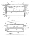
- Fig. 1 is a longitudinal section of an electrolytic cell according to an embodiment of the present invention.
- the electrolytic cell consists basically of a lower base 2, a SPE electrode 6 and an upper base 8.
- the lower base 2 has an effluent exit 1 near the bottom of its left-hand side and is open at the top.
- the SPE electrode 6 is made of an ion-exchange membrane 5 having a layer of cathode active material 3 on the lower surface and a layer of anode active material 4 on the upper surface and is placed within the opening of the lower base 2.
- the upper base 8 has an electrolyte entrance 7 near the top of its right-hand side above the SPE electrode 6 and is open at the bottom.
- the two bases 2 and 8 are secured by means of bolts 11 that pass through annular spaces 9 and 10 that are formed around the respective bases.
- a gas-permeable and liquid-impermeable window 12 is formed on top of the upper base 8.
- Pipe 15 is placed above window 12 for the passage of a fluid to be treated 14 which has a cutout 13 that conforms to the shape of the window 12.
- the electrolyte in the anode compartment contacts the fluid 14 via the window 12.
- the electrolytic cell further includes a cathode current collector 16 for supplying power to the layer of cathode active material 3 and an anode current collector 17 for supplying power to the layer of anode active material 4.
- An electrolyte e.g. aqueous sodium chloride
- Chloride ions are oxidized in the anode compartment to evolve chlorine gas. Because of its small specific gravity, the chlorine gas rises up to window 12, permeates it as indicated by arrows and contacts the fluid 14 in the pipe 15 above the window 12 to thereby sterilize, disinfect or otherwise treat the fluid 14.
- the treated fluid 14 flows through the pipe 15 and is recovered from the system at the left end as viewed in Fig. 1.
- hydroxyl ions and the sodium ions that have permeated the ion-exchange membrane 5 react with each other to produce sodium hydroxide with the simultaneous evolution of hydrogen gas. These products are recovered from the system through effluent exit 1.
- Fig. 2 is a longitudinal section of an electrolytic cell according to another embodiment of the present invetion.
- the electrolytic cell consists basically of a tubular base 23, an ion-exchange membrane 25, a cathode 26 and an anode 27.
- the base 23 is made of a corrosion-resistant material and has an effluent exit 21 near the top and bottom of its left-hand side and an electrolyte entrance in 22 near the top of its right-hand side.
- the ion-exchange membrane 25 is stretched taut between projections 24 on the inner surfaces of the central portion of the base 23.
- the cathode 26 is positioned below the ion-exchange membrane 25 with a slight gap formed there-between, and the anode 27 is positioned above the membrane with a slight gap being also formed therebetween.
- a window 28 is fitted in openings at the top and bottom ends of the cell base 23.
- the apparatus of the second embodiment of the present invention described above is submerged in a fluid to be treated and the gases evolved in the anode and cathode compartments are released through the upper and lower windows 28 into the fluid so as to treat it.
- complicated piping is also unnecessary and the ingress of the fluid being treated into the electrolytic cell is avoided.
- the fluid can be treated without any complicated additional equipment or post-treatments.
- An electrolytic cell of the type shown in Fig. 1 was constructed in the following manner.
- One gram of a lead dioxide powder and 1 g of a suspension of fluorine resin were coated on one side of a perfluoro-sulfonated ion-exchange membrane (Nafion 110) and the coating was fixed by heating at 150°C under a pressure of 1 kg/m2.
- a nickel coating of about 5 ⁇ m thick was formed on the other side of the ion-exchange membrane by conventional electroless plating.
- the resulting ion-exchange membrane was placed as a diaphragm in a cylinder of fluorine resin with its top open.
- a lead oxide coated titanium porous plate serving as a current collector was pressed onto the anode (lead dioxide) side of the ion-exchange membrane whereas a 50- ⁇ m porous nickel plate, thermally sprayed with a nickel powder, was pressed onto the cathode (nickel) side, thereby fabricating an electrolytic cell having a SPE electrode.
- an electrolyte entrance was provided only on the side connecting to the anode compartment and an effluent exit also serving as a hydrogen gas discharge port was provided only on the side connecting to the cathode compartment.
- a three-dimensional titanium filter having a suspension of fluorine resin coated in a thicknes of 0.5 mm on the surfaces was provided as a window in the opening of the cylinder in such a way that it would be substantially parallel to the ion-exchange membrane.
- a pipe for supplying a crude aqueous solution of phosphoric acid containing about 1,300 ppm of COD was attached to the window.
- electrolysis was conducted with pure water being supplied into the electrolytic cell, only oxygen gas containing about 14% ozone was sent through the window into the crude aqueous solution of phosphoric acid and the COD in that solution was reduced to about 10 ppm.
- no increase in the concentration of phosphoric acid in the electrolyte was observed as a result of permeation of the aqueous phosphoric acid solution through the window. Consequently, the concentration of phosphoric acid in the treated fluid was kept constant throughout the treatment.
- An electrolytic cell of the type shown in Fig. 2 was constructed in the following manner.
- a perfluorosulfonated ion-exchange membrane Nafion 312 was used as a diaphragm; a porous titanium plate coated with an electrode catalyst (coated amount: 10 g/m2) that was composed of a composite Ru-Ir-Ti oxide was used as an anode; and a three-dimensional porous nickel plate was used as a cathode.
- the three elements were assembled in a tube of fluorine resin (i.d. 10 cm) with its top and bottom open, thereby fabricating an electrolytic cell.
- An electrolyte entrance and an effluent exit were provided on the side connected to the anode compartment whereas only an effluent exit was provided on the side connected to the cathode compartment.
- a fluorine resin was coated in a thickness of 200 ⁇ m on a metallic filter that was prepared by sintering a titanium powder to prepare a window.
- the window was fitted in the opening above the anode compartment of the electrolytic cell.
- Another window was prepared by a coating a fluorine resin in a thickness of 200 ⁇ m on a metallic filter that was prepared by sintering a nickel powder. This window was fitted in the opening below the cathode compartment.
- the electrolytic cell thus fabricated was filled with a 5% aqueous solution of sodium hydroxide in the cathode compartment and was then submerged in a stream of municipal water.
- electrolysis was conducted in this cell with a saturated aqueous solution of sodium chloride being supplied into the anode compartment at a current density of 30 A/dm2, chlorine was evolved through the window above the anode compartment and hydrogen was evolved through the window below the cathode compartment. Permeation of the electrolyte and municipal water through the windows was not observed at all.
- a gas to be used in the treatment of a fluid is generated in an electrolytic cell having a gas-permeable and liquid-impermeable window and the treatment of the fluid is accomplished by bringing it into contact with the evolved gas via the window.
- the apparatus of the present invention has the following advantages: it is simple in construction; it prevents electrode deterioration due to contamination of the electrolyte; and there is no need to perform a post-treatment such as concentration of the electrolyte.
- electrolytic cell of the present invention Another advantage of the electrolytic cell of the present invention is that it can be directly submerged in the fluid to be treated so that the procedures of its treatment can be further simplified.
Landscapes
- Chemical & Material Sciences (AREA)
- Engineering & Computer Science (AREA)
- Electrochemistry (AREA)
- General Chemical & Material Sciences (AREA)
- Life Sciences & Earth Sciences (AREA)
- Hydrology & Water Resources (AREA)
- Chemical Kinetics & Catalysis (AREA)
- Environmental & Geological Engineering (AREA)
- Water Supply & Treatment (AREA)
- Organic Chemistry (AREA)
- Electrolytic Production Of Non-Metals, Compounds, Apparatuses Therefor (AREA)
- Water Treatment By Electricity Or Magnetism (AREA)
- Electrodes For Compound Or Non-Metal Manufacture (AREA)
Applications Claiming Priority (2)
| Application Number | Priority Date | Filing Date | Title |
|---|---|---|---|
| JP63118915A JPH07106349B2 (ja) | 1988-05-16 | 1988-05-16 | 電解槽 |
| JP118915/88 | 1988-05-16 |
Publications (2)
| Publication Number | Publication Date |
|---|---|
| EP0343122A1 true EP0343122A1 (fr) | 1989-11-23 |
| EP0343122B1 EP0343122B1 (fr) | 1992-11-04 |
Family
ID=14748325
Family Applications (1)
| Application Number | Title | Priority Date | Filing Date |
|---|---|---|---|
| EP89830204A Expired EP0343122B1 (fr) | 1988-05-16 | 1989-05-10 | Cellule électrolytique |
Country Status (4)
| Country | Link |
|---|---|
| US (1) | US4978438A (fr) |
| EP (1) | EP0343122B1 (fr) |
| JP (1) | JPH07106349B2 (fr) |
| DE (1) | DE68903359T2 (fr) |
Cited By (3)
| Publication number | Priority date | Publication date | Assignee | Title |
|---|---|---|---|---|
| WO1994026670A1 (fr) * | 1993-05-12 | 1994-11-24 | Sterling Pulp Chemicals, Ltd. | Production de bioxyde de chlore pour le traitement de l'eau |
| US5965004A (en) * | 1996-03-13 | 1999-10-12 | Sterling Pulp Chemicals, Ltd. | Chlorine dioxide generation for water treatment |
| WO2011135749A1 (fr) * | 2010-04-30 | 2011-11-03 | Aquaecos Ltd. | Ensemble membrane-électrode, cellule électrolytique l'employant, procédé et appareil pour produire de l'eau ozonisée, procédé de désinfection et procédé de traitement d'eaux usées ou de déchets liquides |
Families Citing this family (17)
| Publication number | Priority date | Publication date | Assignee | Title |
|---|---|---|---|---|
| KR920003216B1 (en) * | 1990-03-03 | 1992-04-24 | Samsung Electronic | Apparatus for the production of ozone |
| JP3048612B2 (ja) * | 1990-09-06 | 2000-06-05 | ペルメレック電極株式会社 | 電解オゾン発生装置 |
| US5271813A (en) * | 1993-03-29 | 1993-12-21 | University Of Central Florida | Apparatus and method for the electrolysis of water employing a sulfonated solid polymer electrolyte |
| JPH07120340A (ja) * | 1993-10-22 | 1995-05-12 | Honda Motor Co Ltd | 圧力センサ |
| JPH08105808A (ja) * | 1994-10-05 | 1996-04-23 | Mitsubishi Electric Corp | 圧力センサ |
| JP3035483B2 (ja) * | 1995-11-27 | 2000-04-24 | スガ試験機株式会社 | 酸素・水素電解ガス発生装置 |
| WO2000035813A1 (fr) * | 1998-12-16 | 2000-06-22 | Lynntech, Inc. | Elimination des micro-organismes a un point d'utilisation de sources d'eau potable |
| US6458257B1 (en) | 1999-02-09 | 2002-10-01 | Lynntech International Ltd | Microorganism control of point-of-use potable water sources |
| US6719564B2 (en) * | 2000-03-22 | 2004-04-13 | Chart Inc. | Space simulation chamber and method |
| US6860976B2 (en) * | 2000-06-20 | 2005-03-01 | Lynntech International, Ltd. | Electrochemical apparatus with retractable electrode |
| US6964739B2 (en) | 2000-12-12 | 2005-11-15 | Tersano Inc. | Device and method for generating and applying ozonated water |
| US7029637B2 (en) | 2003-01-09 | 2006-04-18 | H203, Inc. | Apparatus for ozone production, employing line and grooved electrodes |
| KR100872576B1 (ko) * | 2007-07-02 | 2008-12-08 | 삼성전기주식회사 | 수소 발생 장치 및 연료전지 발전 시스템 |
| EP2697730A4 (fr) | 2011-04-15 | 2015-04-15 | Advanced Diamond Technologies Inc | Système et procédé électrochimiques destinés à une génération sur site d'oxydants sous une densité de courant élevée |
| US10239772B2 (en) | 2015-05-28 | 2019-03-26 | Advanced Diamond Technologies, Inc. | Recycling loop method for preparation of high concentration ozone |
| WO2018075920A1 (fr) * | 2016-10-20 | 2018-04-26 | Advanced Diamond Technologies, Inc. | Générateurs d'ozone, procédés de fabrication de générateurs d'ozone et procédés de génération d'ozone |
| CN109626523A (zh) * | 2019-02-01 | 2019-04-16 | 华中师范大学 | 基于离子交换膜的新型光电催化反应器及其在废水处理中的应用 |
Citations (2)
| Publication number | Priority date | Publication date | Assignee | Title |
|---|---|---|---|---|
| US3574084A (en) * | 1969-10-09 | 1971-04-06 | Nasa | Specialized halogen generator for purification of water |
| US4172773A (en) * | 1978-05-11 | 1979-10-30 | Oronzio De Nora Impianti Electrochimici S.P.A. | Novel halogenation process and apparatus |
Family Cites Families (4)
| Publication number | Priority date | Publication date | Assignee | Title |
|---|---|---|---|---|
| US4334968A (en) * | 1979-11-08 | 1982-06-15 | Sweeney Charles T | Apparatus for generation of chlorine/chlorine dioxide mixtures |
| US4443424A (en) * | 1982-09-30 | 1984-04-17 | Shell Oil Company | Method of removing hydrogen sulfide from gases utilizing a polyvalent metal chelate solution and electrolytically regenerating the solution |
| EP0154468B1 (fr) * | 1984-02-24 | 1989-10-04 | Kabushiki Kaisha Toshiba | Membrane perméable pour oxygène |
| US4613415A (en) * | 1984-08-17 | 1986-09-23 | Sophisticated Systems, Inc. | Electrolytic chlorine and alkali generator for swimming pools and method |
-
1988
- 1988-05-16 JP JP63118915A patent/JPH07106349B2/ja not_active Expired - Fee Related
-
1989
- 1989-05-10 EP EP89830204A patent/EP0343122B1/fr not_active Expired
- 1989-05-10 DE DE8989830204T patent/DE68903359T2/de not_active Expired - Fee Related
- 1989-05-16 US US07/352,427 patent/US4978438A/en not_active Expired - Fee Related
Patent Citations (2)
| Publication number | Priority date | Publication date | Assignee | Title |
|---|---|---|---|---|
| US3574084A (en) * | 1969-10-09 | 1971-04-06 | Nasa | Specialized halogen generator for purification of water |
| US4172773A (en) * | 1978-05-11 | 1979-10-30 | Oronzio De Nora Impianti Electrochimici S.P.A. | Novel halogenation process and apparatus |
Cited By (3)
| Publication number | Priority date | Publication date | Assignee | Title |
|---|---|---|---|---|
| WO1994026670A1 (fr) * | 1993-05-12 | 1994-11-24 | Sterling Pulp Chemicals, Ltd. | Production de bioxyde de chlore pour le traitement de l'eau |
| US5965004A (en) * | 1996-03-13 | 1999-10-12 | Sterling Pulp Chemicals, Ltd. | Chlorine dioxide generation for water treatment |
| WO2011135749A1 (fr) * | 2010-04-30 | 2011-11-03 | Aquaecos Ltd. | Ensemble membrane-électrode, cellule électrolytique l'employant, procédé et appareil pour produire de l'eau ozonisée, procédé de désinfection et procédé de traitement d'eaux usées ou de déchets liquides |
Also Published As
| Publication number | Publication date |
|---|---|
| DE68903359T2 (de) | 1993-04-01 |
| JPH01288390A (ja) | 1989-11-20 |
| DE68903359D1 (de) | 1992-12-10 |
| EP0343122B1 (fr) | 1992-11-04 |
| JPH07106349B2 (ja) | 1995-11-15 |
| US4978438A (en) | 1990-12-18 |
Similar Documents
| Publication | Publication Date | Title |
|---|---|---|
| US4978438A (en) | Electrolytic cell | |
| JP3095245B2 (ja) | 電気化学的二酸化塩素発生器 | |
| US4473449A (en) | Flowthrough electrochemical hemodialysate regeneration | |
| US6254762B1 (en) | Process and electrolytic cell for producing hydrogen peroxide | |
| US5460705A (en) | Method and apparatus for electrochemical production of ozone | |
| US4519889A (en) | Halogenation apparatus | |
| AU2009217473B2 (en) | Electrolytic device for generation of pH-controlled hypohalous acid aqueous solutions for disinfectant applications | |
| US5965009A (en) | Method of producing acid water and electrolytic cell therefor | |
| US4798715A (en) | Producing chlorine dioxide from chlorate salt | |
| US5770033A (en) | Methods and apparatus for using gas and liquid phase cathodic depolarizers | |
| EP1090880A1 (fr) | Système et procédé électrolytique de production d'ozone et système de production d' eau ozonisée | |
| US5158658A (en) | Electrochemical chlorine dioxide generator | |
| JP3007137B2 (ja) | 電解オゾン発生方法及び装置 | |
| GB2332210A (en) | Processing waste water | |
| US5565082A (en) | Brine electrolysis and electrolytic cell therefor | |
| CA1171380A (fr) | Methode et dispositif d'oxydation indirecte de l'uree | |
| EP0560740B1 (fr) | Appareil et procédé pour la génération électrolytique d'ozone | |
| EP0230737B1 (fr) | Procédé de pervaporation au travers d'une membrane pour l'obtention de dioxyde de chlore | |
| US5089095A (en) | Electrochemical process for producing chlorine dioxide from chloric acid | |
| JPH10291808A (ja) | 過酸化水素水の製造方法及び装置 | |
| EP0342169B1 (fr) | Ozonisateur électrolytique et procédé pour décomposer un gaz résiduaire utilisant cet ozonisateur | |
| JP3677078B2 (ja) | 過酸化水素水の製造方法及び装置 | |
| JPH101794A (ja) | 電解槽及び電解方法 | |
| GB1567274A (en) | Electrolytic production of hypochloites | |
| KR940010106B1 (ko) | 수성 알카리 금속 염화물 용액의 염소 제거방법 |
Legal Events
| Date | Code | Title | Description |
|---|---|---|---|
| PUAI | Public reference made under article 153(3) epc to a published international application that has entered the european phase |
Free format text: ORIGINAL CODE: 0009012 |
|
| AK | Designated contracting states |
Kind code of ref document: A1 Designated state(s): DE FR GB IT |
|
| 17P | Request for examination filed |
Effective date: 19900120 |
|
| 17Q | First examination report despatched |
Effective date: 19910403 |
|
| ITF | It: translation for a ep patent filed | ||
| GRAA | (expected) grant |
Free format text: ORIGINAL CODE: 0009210 |
|
| AK | Designated contracting states |
Kind code of ref document: B1 Designated state(s): DE FR GB IT |
|
| REF | Corresponds to: |
Ref document number: 68903359 Country of ref document: DE Date of ref document: 19921210 |
|
| ET | Fr: translation filed | ||
| PGFP | Annual fee paid to national office [announced via postgrant information from national office to epo] |
Ref country code: FR Payment date: 19930526 Year of fee payment: 5 |
|
| PLBE | No opposition filed within time limit |
Free format text: ORIGINAL CODE: 0009261 |
|
| STAA | Information on the status of an ep patent application or granted ep patent |
Free format text: STATUS: NO OPPOSITION FILED WITHIN TIME LIMIT |
|
| 26N | No opposition filed | ||
| PG25 | Lapsed in a contracting state [announced via postgrant information from national office to epo] |
Ref country code: FR Effective date: 19950131 |
|
| REG | Reference to a national code |
Ref country code: FR Ref legal event code: ST |
|
| PGFP | Annual fee paid to national office [announced via postgrant information from national office to epo] |
Ref country code: GB Payment date: 19960430 Year of fee payment: 8 |
|
| PGFP | Annual fee paid to national office [announced via postgrant information from national office to epo] |
Ref country code: DE Payment date: 19960628 Year of fee payment: 8 |
|
| PG25 | Lapsed in a contracting state [announced via postgrant information from national office to epo] |
Ref country code: GB Effective date: 19970510 |
|
| GBPC | Gb: european patent ceased through non-payment of renewal fee |
Effective date: 19970510 |
|
| PG25 | Lapsed in a contracting state [announced via postgrant information from national office to epo] |
Ref country code: DE Free format text: LAPSE BECAUSE OF NON-PAYMENT OF DUE FEES Effective date: 19980203 |
|
| PG25 | Lapsed in a contracting state [announced via postgrant information from national office to epo] |
Ref country code: IT Free format text: LAPSE BECAUSE OF NON-PAYMENT OF DUE FEES;WARNING: LAPSES OF ITALIAN PATENTS WITH EFFECTIVE DATE BEFORE 2007 MAY HAVE OCCURRED AT ANY TIME BEFORE 2007. THE CORRECT EFFECTIVE DATE MAY BE DIFFERENT FROM THE ONE RECORDED. Effective date: 20050510 |