EP0343149A2 - Dispositif pour fixer les contre-rails dans les aiguillages - Google Patents
Dispositif pour fixer les contre-rails dans les aiguillages Download PDFInfo
- Publication number
- EP0343149A2 EP0343149A2 EP89890146A EP89890146A EP0343149A2 EP 0343149 A2 EP0343149 A2 EP 0343149A2 EP 89890146 A EP89890146 A EP 89890146A EP 89890146 A EP89890146 A EP 89890146A EP 0343149 A2 EP0343149 A2 EP 0343149A2
- Authority
- EP
- European Patent Office
- Prior art keywords
- recess
- spring element
- rail foot
- tunnel
- upper edge
- Prior art date
- Legal status (The legal status is an assumption and is not a legal conclusion. Google has not performed a legal analysis and makes no representation as to the accuracy of the status listed.)
- Granted
Links
Images
Classifications
-
- E—FIXED CONSTRUCTIONS
- E01—CONSTRUCTION OF ROADS, RAILWAYS, OR BRIDGES
- E01B—PERMANENT WAY; PERMANENT-WAY TOOLS; MACHINES FOR MAKING RAILWAYS OF ALL KINDS
- E01B7/00—Switches; Crossings
- E01B7/02—Tongues; Associated constructions
-
- E—FIXED CONSTRUCTIONS
- E01—CONSTRUCTION OF ROADS, RAILWAYS, OR BRIDGES
- E01B—PERMANENT WAY; PERMANENT-WAY TOOLS; MACHINES FOR MAKING RAILWAYS OF ALL KINDS
- E01B7/00—Switches; Crossings
- E01B7/22—Special sleepers for switches or crossings; Fastening means therefor
Definitions
- the invention relates to a device for fastening stock rails in switches, consisting of a base plate for the stock rail with a slide chair attached to it for the switch tongue and an elongated, preferably plate-shaped spring element for holding down the rail foot, which extends through an approximately perpendicular to the stock rail , tunnel-like recess is passed through the sliding chair, the spring element being insertable into the recess of the sliding chair with a tension that is not sufficient to hold the rail foot down, preferably without tension, and at least one wedge is provided that is separate from the sliding chair and the rail foot and with which the spring element against the Rail base can be clamped, as well as a method for fastening stock rails with such a device.
- a device of the type mentioned in the beginning can be found, for example, in AT-PS 321 345.
- the advantage was achieved that the plate-shaped spring element could be driven largely without tension and was only brought into the desired tensioned position in which the rail foot was held resiliently by driving in the transverse wedge. No special tools were required for the assembly and the spring leaf could simply be inserted into the desired position, after which the desired tension was set by the wedge.
- the invention now aims to provide a simple design of the tunnel-shaped recess of a sliding chair, which can be manufactured with the necessary precision without difficulty in terms of production technology, and further aims to easily adapt the progressive characteristic of a plate-shaped spring element to the desired requirements to be able to adapt.
- the inventive design of Fastening device of the type mentioned essentially in that the upper edge of the tunnel-like recess in the sliding chair is steeper upward with the formation of a kink in the direction of the rail foot than in a flat area in front of the kink and that the separate wedge in the flat area of the upper edge in Distance from the kink of the top edge can be driven.
- this separate wedge can be used to ensure that the plate-shaped spring element after driving in the wedge at a distance from the kink in the tunnel-shaped recess of the sliding chair comes to rest, so that the progressive spring characteristic actually occurs only after a predetermined spring travel.
- the method according to the invention for fastening stock rails with such a device is to be understood, which is advantageously carried out in such a way that the separate wedge is driven in such a way that the spring element is at a predetermined vertical distance from the kink in the tunnel-shaped recess brought.
- the length of the spring travel with the flatter spring characteristic can be specified exactly and in accordance with the requirements, and following the collision of the plate-shaped spring element with the kink in the tunnel-shaped recess, a steeper spring characteristic is achieved, which according to predetermined Travel is limited by a stop on the steeper region of the tunnel-shaped recess.
- the design according to the invention is so made that the upper edge of the tunnel-like recess is formed in longitudinal section by two rectilinear sections which form a raised angle with respect to the recess.
- Such a design can be produced in a simple manner without the risk of reducing the strength properties of the sliding chair and results in a relatively precisely defined attachment point for the beginning of the progressive spring characteristic after a first spring travel with less spring force.
- the design is advantageously made such that the raised angle is selected between 185 ° and 205 °, such an angle having been found to be particularly preferred, in particular with regard to the desired strength of the sliding chair.
- the progressive spring characteristic can be obtained over a certain spring travel with a characteristic which is substantially flatter than can be achieved by using a second stop when springs made of round material are used.
- a progressive spring characteristic should thus be achieved, which is still comparatively flat and differs substantially from a stop on the steeper portion of the tunnel-shaped recess.
- the design is advantageously made such that the distance between the additional wedge and the end of the spring leaf that crosses the rail foot is 25-100% greater than the distance between the kink of the upper edge and the end of the spring leaf that crosses the rail foot.
- a progressive spring characteristic can thus be achieved, in which the adjoining partial areas of the spring characteristic are still relatively flat with respect to a stop, so that at the same time an effective securing of the spring element against breakage is ensured.
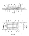
- 1 denotes a stock rail or its base, which rests on a base plate 2.
- 3 designates the sliding chair, which has a layer 4 of slidable material on its surface.
- the sliding chair 3 has a tunnel-shaped recess 5 into which a plate-shaped spring element 6 is inserted to hold down the rail foot of the stock rail 1.
- the rail foot is secured by a stop 7 welded onto the base plate 2, a stop 8 welded onto the base plate 2 being provided to secure the plate-shaped spring element in the operating position, which end 9 faces away from the end rail 9 of the plate-shaped spring element 6 cooperates.
- the spring element 6 is inserted without tension into the tunnel-shaped recess 5 of the sliding chair 3, whereupon a transverse wedge 10 is driven in between the upper edge of the tunnel-shaped recess 5 and the plate-shaped spring element 6 for bracing the spring element 6 against the rail foot 1.
- the upper edge of the tunnel-like recess 5 of the sliding chair 3 has two areas 11 and 12, which run at different inclinations and form a kink 13.
- the area 12 facing the rail foot 1 runs steeper upwards than the area 11 of the upper edge of the tunnel-like recess 5 of the sliding chair 3, the wedge 10 being driven in the flatter area at a distance from the bend 13 to brace the spring element 6 against the rail foot 1 .
- the upper edge of the tunnel-like recess 5 formed by the two rectilinear sections 11 and 12 enclose a raised angle which is between 185 ° and 205 °.
- the transverse wedge 10 is driven in at a distance a from the bend 13 between the regions 11 and 12, which corresponds at most to the distance b between the end 14 of the plate-shaped spring element 6 which overlaps the rail foot 1 and the bend 13.
- the distance a is chosen so that the plate-shaped spring element 6 is a predetermined vertical distance from the bend 13 after driving in the wedge 10.
- a spring force defined by the entire length of the spring element 6 acts first on the rail foot 1, whereupon after a vertical displacement of the spring element 6 in the direction of the bend 13 of the tunnel-like recess 5 of the sliding chair, the spring element abuts the bend 13 arrives, whereupon only the area b between the bend 13 and the end 14 of the spring element facing the rail foot 1 Effect that corresponds to a progressive spring characteristic.
- the spring travel of this section b is limited by a stop at the steeper region 12 of the upper edge of the tunnel-like recess 5 of the sliding chair 3.
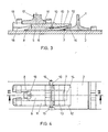
- FIGS. 1 and 2 have been retained for the same components.
- the sliding chair 3 in turn has a tunnel-like recess 5, the upper edge of which is delimited by two rectilinear regions 11 and 12 with different inclinations, which form a bend 13.
- the spring-like element is prestressed by a transverse wedge 10, a vertical distance between the bend 13 and the surface of the plate-shaped element 6 again being intended to remain in the rest position.
- a spring tongue 17 is shown on the sliding chair 3 in the embodiment according to FIG. 3, the sliding chair 3 having a U-shaped recess 18 for fixing the spring tongue 17, through which fastening elements 19 for the spring tongue 17 with the base plate 2 can be connected.
Landscapes
- Engineering & Computer Science (AREA)
- Mechanical Engineering (AREA)
- Architecture (AREA)
- Civil Engineering (AREA)
- Structural Engineering (AREA)
- Chairs For Special Purposes, Such As Reclining Chairs (AREA)
- Railway Tracks (AREA)
- Springs (AREA)
Applications Claiming Priority (2)
| Application Number | Priority Date | Filing Date | Title |
|---|---|---|---|
| AT0133588A AT389721B (de) | 1988-05-20 | 1988-05-20 | Vorrichtung zum befestigen von backenschienen in weichen |
| AT1335/88 | 1988-05-20 |
Publications (3)
| Publication Number | Publication Date |
|---|---|
| EP0343149A2 true EP0343149A2 (fr) | 1989-11-23 |
| EP0343149A3 EP0343149A3 (en) | 1990-08-16 |
| EP0343149B1 EP0343149B1 (fr) | 1993-03-17 |
Family
ID=3511673
Family Applications (1)
| Application Number | Title | Priority Date | Filing Date |
|---|---|---|---|
| EP89890146A Expired - Lifetime EP0343149B1 (fr) | 1988-05-20 | 1989-05-18 | Dispositif pour fixer les contre-rails dans les aiguillages |
Country Status (7)
| Country | Link |
|---|---|
| US (1) | US4981264A (fr) |
| EP (1) | EP0343149B1 (fr) |
| AT (1) | AT389721B (fr) |
| CA (1) | CA1323012C (fr) |
| DE (1) | DE58903775D1 (fr) |
| NO (1) | NO892032L (fr) |
| PT (1) | PT90578B (fr) |
Cited By (7)
| Publication number | Priority date | Publication date | Assignee | Title |
|---|---|---|---|---|
| WO1994005858A1 (fr) * | 1992-09-02 | 1994-03-17 | Bwg Butzbacher Weichenbau Gmbh | Dispositif de fixation de rails |
| DE4309515A1 (de) * | 1993-03-25 | 1994-09-29 | Butzbacher Weichenbau Gmbh | Schienenanordnung |
| WO1994021859A1 (fr) * | 1993-03-25 | 1994-09-29 | Bwg Butzbacher Weichenbau Gmbh | Agencement de rails |
| WO1996041920A1 (fr) * | 1995-06-09 | 1996-12-27 | Vae Aktiengesellschaft | Dispositif permettant de fixer des contre-aiguilles dans des aiguilles |
| EP2397606A2 (fr) | 2010-06-15 | 2011-12-21 | Vae Eisenbahnsysteme Gmbh | Dispositif de fixation d'une contre-aiguille |
| CN112356874A (zh) * | 2020-11-24 | 2021-02-12 | 绵阳市维博电子有限责任公司 | 一种道岔检测系统 |
| EP3945156A1 (fr) * | 2020-07-31 | 2022-02-02 | D.R. Ferroviaria Italia S.r.l. | Palier élastique innovant pour aiguillages ferroviaire, de préférence de type autolubrifiant |
Families Citing this family (5)
| Publication number | Priority date | Publication date | Assignee | Title |
|---|---|---|---|---|
| US5865370A (en) * | 1997-06-06 | 1999-02-02 | Sonneville International Corporation | Rail fastening system for fastening a rail to a rail support and assembly including such rail fastening system coupled to the rail support |
| KR100233091B1 (ko) | 1997-10-23 | 1999-12-01 | 윤종용 | 에이티엠 트래픽 제어장치 및 방법 |
| US6758406B2 (en) | 2002-09-23 | 2004-07-06 | Progress Rail Services Corp. | Rail switch brace |
| DE10353090A1 (de) * | 2003-11-12 | 2005-06-30 | Heim, Armin W., Dipl.-Ing. | Vorrichtung zur Befestigung von Backenschienen in Weichen |
| GB2511046B (en) * | 2013-02-20 | 2015-02-25 | Progress Rail Services Uk Ltd | Track assembly |
Family Cites Families (6)
| Publication number | Priority date | Publication date | Assignee | Title |
|---|---|---|---|---|
| DE646413C (de) * | 1937-06-14 | Lajos Peter | Schienenbefestigung mittels schwingend gelagerter Klemmplatte und Spannkeil | |
| US966284A (en) * | 1909-10-30 | 1910-08-02 | John W Williamson | Combined railroad-tie and rail-fastener. |
| US2462771A (en) * | 1945-08-02 | 1949-02-22 | Philips Calvin | Rail fastener |
| CH526000A (de) * | 1971-01-04 | 1972-07-31 | Armin Dipl Ing Heim | Vorrichtung zum Befestigen von Backenschienen in Weichen |
| AT321345B (de) * | 1973-03-26 | 1975-03-25 | Oesterr Alpine Montan | Vorrichtung zur Befestigung von Backenschienen in Weichen |
| DE3230612A1 (de) * | 1982-08-18 | 1984-02-23 | Schwihag Gesellschaft für Eisenbahnoberbau mbH, 8274 Gottlieben, Thurgau | Vorrichtung zum befestigen von backenschienen oder fahrschienen in weichen |
-
1988
- 1988-05-20 AT AT0133588A patent/AT389721B/de not_active IP Right Cessation
-
1989
- 1989-05-17 PT PT90578A patent/PT90578B/pt active IP Right Grant
- 1989-05-17 US US07/353,025 patent/US4981264A/en not_active Expired - Fee Related
- 1989-05-18 DE DE8989890146T patent/DE58903775D1/de not_active Expired - Fee Related
- 1989-05-18 EP EP89890146A patent/EP0343149B1/fr not_active Expired - Lifetime
- 1989-05-19 NO NO89892032A patent/NO892032L/no unknown
- 1989-05-19 CA CA000600213A patent/CA1323012C/fr not_active Expired - Fee Related
Cited By (11)
| Publication number | Priority date | Publication date | Assignee | Title |
|---|---|---|---|---|
| WO1994005858A1 (fr) * | 1992-09-02 | 1994-03-17 | Bwg Butzbacher Weichenbau Gmbh | Dispositif de fixation de rails |
| DE4309515A1 (de) * | 1993-03-25 | 1994-09-29 | Butzbacher Weichenbau Gmbh | Schienenanordnung |
| WO1994021859A1 (fr) * | 1993-03-25 | 1994-09-29 | Bwg Butzbacher Weichenbau Gmbh | Agencement de rails |
| WO1996041920A1 (fr) * | 1995-06-09 | 1996-12-27 | Vae Aktiengesellschaft | Dispositif permettant de fixer des contre-aiguilles dans des aiguilles |
| AT402747B (de) * | 1995-06-09 | 1997-08-25 | Vae Ag | Vorrichtung zum befestigen von backenschienen in weichen |
| US5899417A (en) * | 1995-06-09 | 1999-05-04 | Vae Aktiengesellschaft | Device for securing stock rails in railway switches |
| EP2397606A2 (fr) | 2010-06-15 | 2011-12-21 | Vae Eisenbahnsysteme Gmbh | Dispositif de fixation d'une contre-aiguille |
| EP2397606A3 (fr) * | 2010-06-15 | 2014-09-03 | voestalpine Weichensysteme GmbH | Dispositif de fixation d'une contre-aiguille |
| EP3945156A1 (fr) * | 2020-07-31 | 2022-02-02 | D.R. Ferroviaria Italia S.r.l. | Palier élastique innovant pour aiguillages ferroviaire, de préférence de type autolubrifiant |
| CN112356874A (zh) * | 2020-11-24 | 2021-02-12 | 绵阳市维博电子有限责任公司 | 一种道岔检测系统 |
| CN112356874B (zh) * | 2020-11-24 | 2021-11-02 | 绵阳市维博电子有限责任公司 | 一种道岔检测系统 |
Also Published As
| Publication number | Publication date |
|---|---|
| EP0343149B1 (fr) | 1993-03-17 |
| PT90578B (pt) | 1994-04-29 |
| EP0343149A3 (en) | 1990-08-16 |
| NO892032L (no) | 1989-11-21 |
| DE58903775D1 (de) | 1993-04-22 |
| CA1323012C (fr) | 1993-10-12 |
| NO892032D0 (no) | 1989-05-19 |
| PT90578A (pt) | 1989-11-30 |
| US4981264A (en) | 1991-01-01 |
| ATA133588A (de) | 1989-06-15 |
| AT389721B (de) | 1990-01-25 |
Similar Documents
| Publication | Publication Date | Title |
|---|---|---|
| DE3400110C2 (fr) | ||
| WO1989012140A1 (fr) | Rail pour vehicules sur rails | |
| AT389721B (de) | Vorrichtung zum befestigen von backenschienen in weichen | |
| WO2011032932A1 (fr) | Système de fixation d'un rail et fixation d'un rail | |
| EP0194550B1 (fr) | Attache de fixation et dispositif de fixation pour rails de chemin de fer | |
| DE2921826A1 (de) | Befestigungsvorrichtung fuer schienen und werkzeug zum einsetzen derselben | |
| EP1167670A2 (fr) | Plaque de fixation pour fixation d'un bras de charnière d'un meuble | |
| DE69516395T2 (de) | Verankerungsvorrichtung für einen träger | |
| AT402747B (de) | Vorrichtung zum befestigen von backenschienen in weichen | |
| DE3300863A1 (de) | Vorrichtung aus einer fuer schienen vorgesehenen schwelle und aus klipsen zur befestigung des fusses einer schiene an der schwelle | |
| DE3230612A1 (de) | Vorrichtung zum befestigen von backenschienen oder fahrschienen in weichen | |
| EP0012265B1 (fr) | Dispositif de fixation de rails | |
| DD156091A5 (de) | Spannbuegel fuer kraftschluessige und elastisch nachgiebige schienenbefestigungen | |
| DE10157676A1 (de) | Einrichtung zum seitlichen Abstützen einer Schiene | |
| DE3820243C2 (de) | Spannklemme und Befestigungsanordnung für Eisenbahnschienen | |
| DE602005000447T2 (de) | Befestigungsvorrichtung einer Schiene für eine Eisenbahnweiche | |
| DE2913297A1 (de) | Anordnung zur befestigung einer schiene auf einem schienentraeger | |
| EP4581210B1 (fr) | Ressort tendeur permettant de retenir un élément de voie ferrée | |
| AT390457B (de) | Spannbuegel zur befestigung von eisenbahnschienen und eisenbahnschienenverankerung | |
| DE3136995C2 (de) | Vorrichtung zum Befestigen von Backenschienen in Weichen | |
| DE3107990A1 (de) | Anker fuer eine in schotter eingebettete schwelle einer gleisanlage | |
| DE3509473A1 (de) | Befestigungsklammer und befestigungsanordnung fuer eisenbahnschienen | |
| EP0341682B1 (fr) | Plaque à nervures avec butée | |
| DE3509472A1 (de) | Verankerungselement fuer befestigungsanordnungen mit befestigungsklammern, insbesondere fuer eisenbahnschienen | |
| CH360085A (de) | Einrichtung zur Befestigung von Eisenbahnschienen auf Schwellen |
Legal Events
| Date | Code | Title | Description |
|---|---|---|---|
| PUAI | Public reference made under article 153(3) epc to a published international application that has entered the european phase |
Free format text: ORIGINAL CODE: 0009012 |
|
| AK | Designated contracting states |
Kind code of ref document: A2 Designated state(s): BE CH DE ES FR GB GR IT LI LU NL SE |
|
| PUAL | Search report despatched |
Free format text: ORIGINAL CODE: 0009013 |
|
| AK | Designated contracting states |
Kind code of ref document: A3 Designated state(s): BE CH DE ES FR GB GR IT LI LU NL SE |
|
| 17P | Request for examination filed |
Effective date: 19901024 |
|
| 17Q | First examination report despatched |
Effective date: 19910621 |
|
| RAP1 | Party data changed (applicant data changed or rights of an application transferred) |
Owner name: VOEST-ALPINE EISENBAHNSYSTEME GESELLSCHAFT M.B.H. |
|
| GRAA | (expected) grant |
Free format text: ORIGINAL CODE: 0009210 |
|
| RAP1 | Party data changed (applicant data changed or rights of an application transferred) |
Owner name: VOEST-ALPINE EISENBAHNSYSTEME AKTIENGESELLSCHAFT |
|
| AK | Designated contracting states |
Kind code of ref document: B1 Designated state(s): BE CH DE ES FR GB GR IT LI LU NL SE |
|
| PG25 | Lapsed in a contracting state [announced via postgrant information from national office to epo] |
Ref country code: ES Free format text: THE PATENT HAS BEEN ANNULLED BY A DECISION OF A NATIONAL AUTHORITY Effective date: 19930317 Ref country code: BE Effective date: 19930317 |
|
| REF | Corresponds to: |
Ref document number: 58903775 Country of ref document: DE Date of ref document: 19930422 |
|
| ITF | It: translation for a ep patent filed | ||
| GBT | Gb: translation of ep patent filed (gb section 77(6)(a)/1977) |
Effective date: 19930616 |
|
| REG | Reference to a national code |
Ref country code: GR Ref legal event code: FG4A Free format text: 3007886 |
|
| EN | Fr: translation not filed | ||
| ET | Fr: translation filed | ||
| REG | Reference to a national code |
Ref country code: FR Ref legal event code: R1 |
|
| REG | Reference to a national code |
Ref country code: FR Ref legal event code: DS |
|
| PLBE | No opposition filed within time limit |
Free format text: ORIGINAL CODE: 0009261 |
|
| STAA | Information on the status of an ep patent application or granted ep patent |
Free format text: STATUS: NO OPPOSITION FILED WITHIN TIME LIMIT |
|
| 26N | No opposition filed | ||
| PGFP | Annual fee paid to national office [announced via postgrant information from national office to epo] |
Ref country code: LU Payment date: 19940531 Year of fee payment: 6 |
|
| EAL | Se: european patent in force in sweden |
Ref document number: 89890146.7 |
|
| PGFP | Annual fee paid to national office [announced via postgrant information from national office to epo] |
Ref country code: DE Payment date: 19950418 Year of fee payment: 7 Ref country code: CH Payment date: 19950418 Year of fee payment: 7 |
|
| PGFP | Annual fee paid to national office [announced via postgrant information from national office to epo] |
Ref country code: GB Payment date: 19950419 Year of fee payment: 7 |
|
| PGFP | Annual fee paid to national office [announced via postgrant information from national office to epo] |
Ref country code: FR Payment date: 19950420 Year of fee payment: 7 |
|
| PGFP | Annual fee paid to national office [announced via postgrant information from national office to epo] |
Ref country code: SE Payment date: 19950424 Year of fee payment: 7 |
|
| PGFP | Annual fee paid to national office [announced via postgrant information from national office to epo] |
Ref country code: GR Payment date: 19950428 Year of fee payment: 7 |
|
| PG25 | Lapsed in a contracting state [announced via postgrant information from national office to epo] |
Ref country code: LU Free format text: LAPSE BECAUSE OF NON-PAYMENT OF DUE FEES Effective date: 19950518 |
|
| PGFP | Annual fee paid to national office [announced via postgrant information from national office to epo] |
Ref country code: NL Payment date: 19950531 Year of fee payment: 7 |
|
| PG25 | Lapsed in a contracting state [announced via postgrant information from national office to epo] |
Ref country code: GB Effective date: 19960518 |
|
| PG25 | Lapsed in a contracting state [announced via postgrant information from national office to epo] |
Ref country code: SE Effective date: 19960519 |
|
| PG25 | Lapsed in a contracting state [announced via postgrant information from national office to epo] |
Ref country code: LI Effective date: 19960531 Ref country code: CH Effective date: 19960531 |
|
| PG25 | Lapsed in a contracting state [announced via postgrant information from national office to epo] |
Ref country code: GR Free format text: THE PATENT HAS BEEN ANNULLED BY A DECISION OF A NATIONAL AUTHORITY Effective date: 19961130 |
|
| PG25 | Lapsed in a contracting state [announced via postgrant information from national office to epo] |
Ref country code: NL Effective date: 19961201 |
|
| REG | Reference to a national code |
Ref country code: GR Ref legal event code: MM2A Free format text: 3007886 |
|
| GBPC | Gb: european patent ceased through non-payment of renewal fee |
Effective date: 19960518 |
|
| REG | Reference to a national code |
Ref country code: CH Ref legal event code: PL |
|
| PG25 | Lapsed in a contracting state [announced via postgrant information from national office to epo] |
Ref country code: FR Effective date: 19970131 |
|
| PG25 | Lapsed in a contracting state [announced via postgrant information from national office to epo] |
Ref country code: DE Effective date: 19970201 |
|
| EUG | Se: european patent has lapsed |
Ref document number: 89890146.7 |
|
| NLV4 | Nl: lapsed or anulled due to non-payment of the annual fee |
Effective date: 19961201 |
|
| REG | Reference to a national code |
Ref country code: FR Ref legal event code: ST |
|
| PG25 | Lapsed in a contracting state [announced via postgrant information from national office to epo] |
Ref country code: IT Free format text: LAPSE BECAUSE OF NON-PAYMENT OF DUE FEES;WARNING: LAPSES OF ITALIAN PATENTS WITH EFFECTIVE DATE BEFORE 2007 MAY HAVE OCCURRED AT ANY TIME BEFORE 2007. THE CORRECT EFFECTIVE DATE MAY BE DIFFERENT FROM THE ONE RECORDED. Effective date: 20050518 |