EP0343169B1 - Zeltkonstruktion - Google Patents
Zeltkonstruktion Download PDFInfo
- Publication number
- EP0343169B1 EP0343169B1 EP88900833A EP88900833A EP0343169B1 EP 0343169 B1 EP0343169 B1 EP 0343169B1 EP 88900833 A EP88900833 A EP 88900833A EP 88900833 A EP88900833 A EP 88900833A EP 0343169 B1 EP0343169 B1 EP 0343169B1
- Authority
- EP
- European Patent Office
- Prior art keywords
- modular tent
- tent structure
- peripheral frame
- crown joint
- modular
- Prior art date
- Legal status (The legal status is an assumption and is not a legal conclusion. Google has not performed a legal analysis and makes no representation as to the accuracy of the status listed.)
- Expired
Links
- 230000002093 peripheral effect Effects 0.000 claims abstract description 54
- 230000014759 maintenance of location Effects 0.000 claims abstract description 7
- 230000015572 biosynthetic process Effects 0.000 claims abstract description 3
- 238000005755 formation reaction Methods 0.000 claims abstract description 3
- 239000011324 bead Substances 0.000 claims description 2
- XLYOFNOQVPJJNP-UHFFFAOYSA-N water Substances O XLYOFNOQVPJJNP-UHFFFAOYSA-N 0.000 claims 5
- 230000000694 effects Effects 0.000 claims 1
- 230000037431 insertion Effects 0.000 claims 1
- 238000003780 insertion Methods 0.000 claims 1
- 230000000717 retained effect Effects 0.000 claims 1
- 239000000463 material Substances 0.000 description 9
- 238000010276 construction Methods 0.000 description 5
- 239000004033 plastic Substances 0.000 description 5
- 229920003023 plastic Polymers 0.000 description 5
- 230000004308 accommodation Effects 0.000 description 4
- 239000004744 fabric Substances 0.000 description 4
- 238000000429 assembly Methods 0.000 description 3
- 238000001125 extrusion Methods 0.000 description 2
- 230000004048 modification Effects 0.000 description 2
- 238000012986 modification Methods 0.000 description 2
- 239000007787 solid Substances 0.000 description 2
- 239000004677 Nylon Substances 0.000 description 1
- XAGFODPZIPBFFR-UHFFFAOYSA-N aluminium Chemical compound [Al] XAGFODPZIPBFFR-UHFFFAOYSA-N 0.000 description 1
- 229910052782 aluminium Inorganic materials 0.000 description 1
- 239000004411 aluminium Substances 0.000 description 1
- 238000004873 anchoring Methods 0.000 description 1
- 238000009408 flooring Methods 0.000 description 1
- 239000007788 liquid Substances 0.000 description 1
- 229920001778 nylon Polymers 0.000 description 1
- 238000000926 separation method Methods 0.000 description 1
- 125000006850 spacer group Chemical group 0.000 description 1
- 239000002023 wood Substances 0.000 description 1
Images




Classifications
-
- E—FIXED CONSTRUCTIONS
- E04—BUILDING
- E04H—BUILDINGS OR LIKE STRUCTURES FOR PARTICULAR PURPOSES; SWIMMING OR SPLASH BATHS OR POOLS; MASTS; FENCING; TENTS OR CANOPIES, IN GENERAL
- E04H15/00—Tents or canopies, in general
- E04H15/32—Parts, components, construction details, accessories, interior equipment, specially adapted for tents, e.g. guy-line equipment, skirts, thresholds
- E04H15/58—Closures; Awnings; Sunshades
-
- E—FIXED CONSTRUCTIONS
- E04—BUILDING
- E04B—GENERAL BUILDING CONSTRUCTIONS; WALLS, e.g. PARTITIONS; ROOFS; FLOORS; CEILINGS; INSULATION OR OTHER PROTECTION OF BUILDINGS
- E04B1/00—Constructions in general; Structures which are not restricted either to walls, e.g. partitions, or floors or ceilings or roofs
- E04B1/343—Structures characterised by movable, separable, or collapsible parts, e.g. for transport
- E04B1/344—Structures characterised by movable, separable, or collapsible parts, e.g. for transport with hinged parts
- E04B1/3441—Structures characterised by movable, separable, or collapsible parts, e.g. for transport with hinged parts with articulated bar-shaped elements
-
- E—FIXED CONSTRUCTIONS
- E04—BUILDING
- E04H—BUILDINGS OR LIKE STRUCTURES FOR PARTICULAR PURPOSES; SWIMMING OR SPLASH BATHS OR POOLS; MASTS; FENCING; TENTS OR CANOPIES, IN GENERAL
- E04H15/00—Tents or canopies, in general
- E04H15/32—Parts, components, construction details, accessories, interior equipment, specially adapted for tents, e.g. guy-line equipment, skirts, thresholds
- E04H15/322—Stretching devices
-
- E—FIXED CONSTRUCTIONS
- E04—BUILDING
- E04H—BUILDINGS OR LIKE STRUCTURES FOR PARTICULAR PURPOSES; SWIMMING OR SPLASH BATHS OR POOLS; MASTS; FENCING; TENTS OR CANOPIES, IN GENERAL
- E04H15/00—Tents or canopies, in general
- E04H15/32—Parts, components, construction details, accessories, interior equipment, specially adapted for tents, e.g. guy-line equipment, skirts, thresholds
- E04H15/34—Supporting means, e.g. frames
- E04H15/44—Supporting means, e.g. frames collapsible, e.g. breakdown type
- E04H15/48—Supporting means, e.g. frames collapsible, e.g. breakdown type foldable, i.e. having pivoted or hinged means
- E04H15/50—Supporting means, e.g. frames collapsible, e.g. breakdown type foldable, i.e. having pivoted or hinged means lazy-tongs type
Definitions
- This invention relates to tent structures and especially but not exclusively to modular tent structures which can be used, inter alia, by fighting and emergency services for personnel accommodation and disaster relief reception area and accommodation but which also finds use in exhibition accommodation and social accommodation such as, for example, weddings or barres.
- US-A-3810481 discloses a modular tent structure having a canopy structure comprising a peripheral frame having corner crown joints to which are bolted laterally-extending interconnecting support members, and diagonally-disposed stay members which are pivoted to a central axially-extendible mast structure, there being adjustable tie rods pivotally connecting each diagonal stay member and the central mast structure.
- US-A-2151908 discloses a collapsible tent structure having a canopy structure comprising a peripheral frame having two opposed collapsible sides, each of which is constituted by a central crown joint structure to each side of which is pivoted one end of a laterally-extending support member, whereof the other end is connected to a corner fixture, a vertical leg of the tent structure, there being a tie member releasably pivoted at one end to the crown joint structure below the support member with its other end connected to the respective corner fixture.
- the peripheral frame supports a covering roof sheet which is also supported within the peripheral frame by a framework of a ridge pole connecting the two opposed collapsible sides and cross bow members parallel with the latter and connected to the ridge pole and two other opposed sides of the peripheral frame.
- a modular tent structure comprising a canopy structure (20) including a peripheral frame (23) adapted to support a covering roof sheet (24) and constituted by peripheral sides and crown joint structures (35), the peripheral frame (23) surrounding a centrally-disposed, axially-extendible mast structure (22) which is releasably connected to each crown joint structure (35) of the peripheral frame (23) by a bracing member (25), the tent structure being characterised in that each peripheral side of the peripheral frame (23) is collapsible and comprises a respective centrally-disposed crown joint structure (35) to each side of which is pivoted a laterally-extending roof sheet support member (34) with tie member (43) releasably connecting each of the pair of laterally-extending support members (34) to the respective central crown joint structure (35) and in that the ends of the bracing members (25) releasably connected to the crown joint structures (35) of adjacent peripheral sides of the peripheral frame (23) are interconnected by flexible tensioning elements (69).
- a canopy structure which for storage and transport purposes, can readily be disassembled into collapsible sub-assemblies, one of which comprises a tetrahedron structure constituted by the mast structure, bracing members and flexible tensioning elements, the peripheral sides of the peripheral frame being readily collapsible by releasing the tie members from their respective central crown joint structures.
- the flexible tensioning elements connecting adjacent peripheral sides of the peripheral frame through the intermediary of the bracing members serve to prevent outward splaying of the peripheral frame if the canopy structure is placed under tension, for example, by snow loading.
- a modular tent structure comprising a canopy structure adapted to be supported above ground by corner pillars, each pillar having on two adjacent faces connecting or haunch plates to which the canopy structure can be detachably connected, and the pillars having open vertical housings or formations for receiving side wall retention elements.
- a tent arrangement comprising, in interconnected relationship, a plurality of tent modules as hereinbefore defined.
- the modular tent structure comprises a canopy structure 20 supported by four corner pillars 21 and having a central mast structure 22 serving to provide the canopy structure 20 with downwardly sloping or inclined elevations from the centre of the canopy structure 20.
- the canopy structure 20 includes a foldable collapsible peripheral frame 23 to each corner of which is detachably connected one of the corner pillars 21, and a covering sheet 24 of fabric, plastics material or any other convenient form of material defining the roof of the modular tent structure.
- the covering roof sheet 24 is connected to the peripheral frame 23 and the central mast structure 22.
- the covering roof sheet 2 4 has an overhanging flap (not shown) which depends vertically at each side of the modular tent structure to provide a peripheral cowl for weatherproof purposes.
- Bracing members 25 are pivotally or hingedly interconnected with the central mast structure 22 and detachably connected to the peripheral frame 23.
- the major structural components of the modular tent structure are formed of aluminium extrusions which provide a strong robust but lightweight assembly.
- Each corner pillar 21 (see especially Fig. 1C) comprises a central hollow octagonal configuration 26 having four integral peripheral webs 27 defining a square open at the corners to define along the length of each corner of the pillar 21 a triangular housing 28 open to the exterior of the pillar 21 and which may be employed for connecting to the pillar 21, a side wall of the modular tent structure, a pillar of an adjacent modular tent structure, other vertical structure such, for example, as a vertical fabric or plastics sheet defining a privacy shield, or a guying system for the modular tent structure.
- the corner pillar 21 is height adjustable (see Fig. 11) having a foot 21A securable to the ground or other supporting surface by bolts, spikes or similar 21B, the foot 21A mounting an upstanding locating rod 21C formed with vertically-spaced holes 21D.
- the rod 21C is inserted into a pillar 21, whereof the webs 27 are apertured and provided with locating bushes as indicated at 27A to permit alignment of the bushed apertures 27A with selected holes 21D so that the rod 21C and pillar 21 can be detachably secured together by a pin 27B held in place by a clip 27C in know manner.
- the locating rod 21C is formed wih a fixed bottom cross-pin 21E for a purpose to be described later.
- pillar height adjustment Any other convenient form of pillar height adjustment may be employed.
- the feet 21A are conveniently shaped as shown in Fig. 11 to be assembled in a group of two, three or four as required.
- a plastics tray 21F formed with a hole or holes 21G for drainage purposes.
- connection plates 30 To each of two adjacent sides of each pillar 21 is secured a pair of parallel substantially triangular connection or haunch plates 29 which are connected to the adjacent face of the corner pillar 21 by connection plates 30.
- the latter are bolted to the face of the pillar 21 as indicated at 31 and extend between the parallel haunch plates 29 to which they are bolted as indicated at 32.
- the parallel haunch plates 29 are rigidly interconnected by hollow spacers 33 rivetted through the haunch plates 29.
- the peripheral frame 23 is connected to the corner pillars 21 through the intermediary of the haunch plates 29 as will be later described.
- the peripheral frame 23 is four sided and each side is identical and one of which will now be described.
- Each side of the peripheral frame 23 comprises a pair of square sectioned hollow extrusions defining support members 34 which when the modular tent structure is erected are inclined upwardly from the corner pillars 21 to a central crown joint structure 35.
- each support member 34 receives a solid hinge bar 36 which is slotted as indicated at 37 to engage the upper wall.
- the bar 36 is bolted to the upper wall as indicated at 38, and is of forked construction as indicated at 36A for pivotal connection to the crown joint structure 35 as indicated at 39.
- the central crown joint structure 35 comprises a T-shaped member 40 with a top plate 41 disposed substantially in a plane at right angles to the plane containing the T-shaped member 40.
- pivotal connections 39 between the hinge plates 37 and the crown joint structure 35 are at the ends of the cross bar of the T-shaped member 40 as can be seen from Figs. 4 and 5.
- a slot 42 is formed in the T-shaped member 40 at the junction of the stem and cross bar, for a purpose which will be hereinafter described.
- the support members 34 and crown joint structure 35 are interconnected by a tie member 43 of upwardly opened channel configuration.
- Each support member 34 has bolted, as indicated at 44, to its under side a connection plate 45 similar to connection plate 30 and the adjacent end of the tie member 43 is pivotally connected to the connection plate 45 as indicated at 46.
- One pivotal connection 46 is permanent while the other is releasable.
- the web of the channel member 43 is slotted at 47 and the bottom end of the T-shaped member 40 extends through the slot 47 and is formed with a hole which receives a retention pin 48 detachably to interconnect the T-shaped member 40 and the tie member 43.
- connection plates 49 identical to connection plates 30, which plates 49 extend between the haunch plates 29 to permit the support members 34 and consequently the sides of the peripheral frame 23 to be bolted as indicated at 50 to the haunch plates 29 connected to the vertical pillars 21.
- each haunch plate 29 is stepped as indicated at 29A, the lower end of the respective support member 34 overhanging the step 29A.
- the sides of the peripheral frame 23 are tied together by a nylon braided rope 51 connecting the lower adjacent ends of the support members 34 of adjacent sides.
- the braided connecting ropes 51 are secured to their respective support members 34 by clamp plates 52 bolted to a side wall of each respective support member 34.
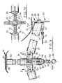
- the central mast structure 22 comprises an outer sleeve 54 to which, at diametrically opposed locations, are welded pairs of parallel plates 55 between which are received plates 56 welded to the adjacent ends of tubular bracing members 25.
- Each plate 56 is pivotally connected between a respective pair of plates 55 as indicated at 57 so that the bracing members 25 are pivotally connected to the outer sleeve 54 at the inner ends of the bracing members 25.
- the outer sleeve 54 is formed at its lower end with two diametrically opposed, mirror image, bayonet slots 58, and inside the outer sleeve 54 is a tubular mast 59 adapted removably to receive a short tube 60 to the upper end of which is welded a lower clamp plate 80 of a clamp structure 81.
- the lower end of the mast 59 is closed by a plate 61 through which extends a vertical screw-threaded spindle or bar 62.
- a lower end 63 of the screw-threaded bar 62 which is of non-screw-threaded configuration extends through a block 64 carrying cross pins or posts 65 which project from opposed sides of the block 64 at each end at right angles to the lower end 63 of the screw-threaded bar 62.
- a handling or jacking ring 66 is connected to the lower end 63 below the block 64.
- the block 64 and the cross pin 65 are therefore secured on the lower end 63 of the screw-threaded bar 62 between the jacking ring 66 and a shoulder defined by the difference in the cross sectional areas of the screw-threaded bar 62 and its lower end 63.
- the block 64 and cross pin 65 and the lower end 63 of the screw-threaded bar 62 are relatively rotatable.
- the ends of the cross pin 65 are aligned with the open bottom ends of the mirror image bayonet slots 58 and the mast 59 is pushed upwardly relative to the outer sleeve 54, the cross pin 65 then being dropped into the lateral portions of the bayonet slots 58, as it is usual, axially to locate the block 64 and cross pin 65 and consequently the mast 59 relative to the outer sleeve 54.
- the lower surface of the block 64 has two right-angled slots (not shown) cut in it, either being engageable with a keying pin 63A on the lower end 63 below the cross pin 65.
- the block 64 can be pushed up to engage the keying pin, the mast 59 raised relative to the sleeve 54, and the bayonet connection made using only one hand. Such one-handed operation is obviously desirable.
- the tube 60 and its clamp structure 81 contacts the under side of the covering roof sheet 24, and is preferably secured thereto.
- the mast 59 can be caused to be moved upwardly relative to the outer sleeve 54 thus raising the centre of the covering roof sheet 24 and applying tension thereto.
- each bracing member 25 has welded to it a plate 67 having an apertured lug 68.
- This apertured lug 68 projects through the slot 42 in the T-shaped member 40 of the crown joint structure 35 at the respective side of the peripheral frame 23 and a pin (not shown) extends through the aperture or hole 69 in the lug 68 to secure the lower end of each bracing member 25 detachably to the crown joint structure 35 of its respective side.
- each bracing member 25 extends below the latter at its lower end and the bracing members 25 of adjacent peripheral frame sides are connected together by high tensile cables 69 connected by shackles 70 to the respective plates 67 of the bracing members 25.
- the webbing belts 71 are connected to the top plates 41 by buckles 72 bolted to the top plates 41 as indicated at 72A.
- the centres of the webbing belts 71 are secured by the clamp structure 81. More specifically, they are held between the bottom clamp plate 80 and an upper clamp plate 82, the clamp plates 80 and 82 being bolted together (not shown)
- plastics material or other convenient material can be fitted and are secured by rigid elements at each end which are accommodated in the housings 28 of the corner pillars 21.
- a side wall 83 is indicated in Figs. 11 and 12B which is engaged in the appropriate housing 28 by a bead 84 extending the height of the wall 83 and secured, thereto by any convenient means as indicated at 85.
- the bottom of the side wall 83 is tethered to the pillar 21 by a cable or similIar 87 which is hitched around the cross-pin 21E.
- the side wall 83 is also tethered to the edge of a floor of any convenient construction (not shown) by elastic cord fasteners 88 (only one shown) or similar secured to a welded-on strip of material 89 having holes 89A through which the cord fasteners 88 are secured.
- the cord fasteners 88 are pegged or otherwise fastened to the ground.
- Adjacent support members 34 are also bolted together.
- These cables 92 are normally collected and stored at or adjacent the appropriate pillar 21 when not in use.
- each bracing member 25 is disconnected from its respective crown joint structure 35 (by removal of the securing pin (not shown) from lug 68 and separation of lug 68 from the slot 42 in the crown joint structure 35) and the crown joint structures 35 are released from the tie bars 43 (by withdrawal of retention pins 48), the releasable end of each tie bar 43 being detached from its connection plate 45 (by withdrawal of the respective pivotal pin 46).
- the mast structure 22 without tube 60 and the clamp structure 81, and the bracing members 25 and connected high tensile cables 69 constituting a tetrahedron structure are separated from the canopy constituted by side members 34, 35 and 43, the webbing straps 71, covering roof sheet 24, the tube 60 and the clamp structure 81 for storage and transport purposes.
- the structural components of the canopy as defined can be bundled together and wrapped around the covering roof sheet 24.
- the modular tent structure sub-assemblies namely corner pillars, tetrahedron structure and canopy, can be stored, for example, in a convenient bag enclosure, or simply strapped or otherwise tied in the folded collapsed position.
- the tetrahedron structure is first laid out on the ground in the extended position, i.e bracing members 25 radiating outwards from the mast structure 22.
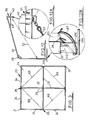
- the canopy is then spread into open condition, i.e. the four corners of the peripheral frame 23 designated A, C, G, E in Fig. 13 are moved both peripherally outwards from the crown joint structures designated B, D, F, H and away from each other so that the four sides of the peripheral frame 23 are in extended position with the support members extending laterally away from the crown joint structures B, D, F, H (Fig. 11A).
- the opened canopy is laid on top of the opened tetrahedron structure, and each released end of each tie member is then connected once again to its respective support member, and each crown joint structure is connected to its respective tie bar as previously described.
- the tetrahedron structure is now connected via the bracing members to the crown joint structures.
- peripheral frame is of rigid square construction with the central mast structure designated J still in collapsed position.
- the central mast structure J is now axially adjusted to make the bayonet connection (bayonet slots 58, block 64 and a cross pin 65) which raises the covering roof sheet 24 at the centre.
- the mast 59 is then jacket upwardly by the screw-threaded bar 62 as previously described to tension the covering roof sheet 24 relative to the peripheral frame 23 as shown in Fig. 13B.
- Positioning members 93 with wedge-shaped recesses are fitted between the corners of adjacent sides of the peripheral frame 23 to locate and hold same in extended position.
- Side walls 83 can now be connected across the open sides of the erected modular tent structure (Fig. 13C) by appropriately engaging the retention members (85, 86) in the housings 28 of the corner pillars.
- the side walls 83 can alternatively be fitted to the support members 34 before the corner pillar 21 is connected to the fully erect canopy structure.
- the side walls will have a door and, of course, if required one or more of the side walls may be provided with a transparent area to form a window.
- the side walls may be completely transparent and they may of course be of solid construction i.e. of wood or other convenient rigid material such as rigid plastics material. Any convenient form of flooring can be provided within the modular tent structure.
- Two or more tent modules can be connected together to provide a larger covered area than a single tent module. This is effected by butting together the sides of two or more tent modules as hereinbefore described and bolting the adjacent corner pillars and support members together.
- haunch Diates 29 can be provided on three or four sides of the corner pillars 21 which would permit the connection of tent modules together with only one of the tent modules having four corner pillars while the others would have only one or two corner pillars at the side outboard from the tent module with the four corner pillars 21.
- the material from which the side walls 83 is formed is cut on a bias, i.e. the fabric or other flexible material from which the side walls 83 are formed is cut at an angle to the warp direction, and this provides an extremely strong and flexibly rigid side wall.
Landscapes
- Engineering & Computer Science (AREA)
- Architecture (AREA)
- Civil Engineering (AREA)
- Structural Engineering (AREA)
- Physics & Mathematics (AREA)
- Electromagnetism (AREA)
- Tents Or Canopies (AREA)
- Separation Using Semi-Permeable Membranes (AREA)
Claims (25)
- Modularer Zeltaufbau, umfassend einen Baldachinaufbau (20), welcher einen Umfangsrahmen (23) umfaßt, der eine Abdeck-Dachplane (24) tragen kann und aus Umfangsseiten und Kronenverbindungsaufbauten (35) besteht, wobei der Umfangsrahmen (23) einen zentral angeordneten, axial ausfahrbaren Mastaufbau (22) umgibt, der durch ein Verstrebungsglied (25) mit jedem Kronenverbindungsaufbau (35) des Umfangsrahmens (23) lösbar verbunden ist, wobei der Zeltaufbau dadurch gekennzeichnet ist, daß jede Umfangsseite des Umfangsrahmens (23) zusammenklappbar ist und einen jeweiligen zentral angeordneten Kronenverbindungsaufbau (35) umfaßt, an den auf jeder Seite ein sich seitlich erstreckendes Dachplanen-Stützglied (34) angelenkt ist, wobei ein Bindeglied (43) jedes Paar der sich seitlich erstreckenden Stützglieder (34) mit dem jeweiligen zentralen Kronenverbindungsaufbau (35) lösbar verbindet, und daß die lösbar mit den Kronenverbindungsaufbauten (35) benachbarter Umfangsseiten des Umfangsrahmens (23) verbundenen Enden der Verstrebungsglieder (25) durch elastische Spannelemente (69) untereinander verbunden sind.
- Modularer Zeltaufbau nach Anspruch 1, dadurch gekennzeichnet, daß die benachbarten Enden benachbarter Stützglieder (34) benachbarter Umfangsseiten elastisch zusammengebunden (51) sind.
- Modularer Zeltaufbau nach Anspruch 1 oder 2, dadurch gekennzeichnet, daß der zentrale Mastaufbau (22) und jeder zentrale Kronenverbindungsaufbau (35) durch elastische Halter (71), vorzugsweise Gurtbänder, untereinander verbunden sind, wobei die Halter (71) unter der Abdeck-Dachplane (24) zum Stützen derselben, wenn die Abdeck-Dachplane (24) über dem Baldachinaufbau (20) angebracht ist, angeordnet sind.
- Modularer Zeltaufbau nach einem der Ansprüche 1 bis 3, dadurch gekennzeichnet, daß jeder zentrale Kronenverbindungsaufbau (35) ein hängendes Glied (40) umfaßt, das sich durch einen von dem jeweiligen Bindeglied (43) gebildeten Schlitz (47) erstrecken kann, wobei ein Arretierstift (48) zur lösbaren Eingriffnahme des hängenden Glieds (40) unterhalb des Bindeglieds (43) vorgesehen ist, um den zentralen Kronenverbindungsaufbau (35) und das Bindeglied (43) abnehmbar aneinander zu befestigen.
- Modularer Zeltaufbau nach einem Anspruch 4, dadurch gekennzeichnet, daß jeder zentrale Kronenverbindungsaufbau (35) aus einem eine Querstange und einen hängenden Stamm bildenden T-förmigen Glied besteht, wobei die Stützglieder (34) mit jeweiligen Enden der Querstange schwenkbar verbunden sind und der das hängende Glied darstellende Stamm sich durch den Schlitz (48) im jeweiligen Bindeglied (43) ertstreckt (40).
- Modularer Zeltaufbau nach einem der Ansprüche 1 bis 5, dadurch gekennzeichnet, daß die elastischen Spannelemente (69) dehnbare Seile sind.
- Modularer Zeltaufbau nach Anspruch 6, dadurch gekennzeichnet, daß einander entgegengesetzte Enden jedes dehnbaren Seils (69) mit einer mit den auf der Seite des zentralen Kronenverbindungsaufbaus liegenden Enden der Verstrebungsglieder (25) verbundenen Platte (67) verbunden sind.
- Modularer Zeltaufbau nach Anspruch 7, dadurch gekennzeichnet, daß die Platte (67) jedes Verstrebungsglieds (25) mit einem Ansatz (68) ausgebildet ist, der sich durch einen vom jeweiligen Kronenverbindungsaufbau (35) gebildeten Schlitz (42) erstrecken und mit einem Stift lösbar damit in Verbindung gehalten werden kann.
- Modularer Zeltaufbau nach einem der Ansprüche 1 bis 8, dadurch gekennzeichnet, daß der zentrale Mastaufbau (22) folgendes umfaßt: Einen Mast (59) und eine diesen umgebende Hülse (54), die relativ zueinander axial beweglich sind, wobei die Hülse (54) in einer axial ausgefahrenen Position abnehmbar befestigt (58, 65) werden kann, und eine Verstelleinrichtung (61, 62) zum Bewegen des Masts (59) relativ zu der ihn umgebenden Hülse (54), während er sich in der axial ausgefahrenen Position befindet, zur Steigerung oder Verminderung der Spannung in der Abdeck-Dachplane (24), wenn diese über dem Baldachinaufbau (20) angebracht wird.
- Modularer Zeltaufbau nach Anspruch 9, dadurch gekennzeichnet, daß die Hülse (54) mit einander entgegengesetzten Bajonettschlitzen (58) ausgebildet ist, mit denen ein Stift (65) zusammenarbeiten kann, wobei der Stift (65) von einer innerhalb des Masts (59) untergebrachten Spindel (62) getragen wird.
- Modularer Zeltaufbau nach Anspruch 10, dadurch gekennzeichnet, daß die Spindel (62) eine Schraube umfaßt, die den Mast (59) schraubend in Eingriff nimmt, wodurch eine relative Drehung zwischen dem Mast (59) und der Hülse (54) eine relative Axialbewegung zwischen ihnen bewirkt.
- Modularer Zeltaufbau nach einem der Ansprüche 1 bis 11, dadurch gekennzeichnet, daß der Baldachinaufbau (20) über der Erde mit Eckpfosten (21) gestützt werden kann, wobei jeder Pfosten (21) auf zwei benachbarten Flächen Verbindungs- oder Zwichelplatten (29) aufweist, mit denen der Baldachinaufbau (20) abnehmbar verbunden werden kann, und wobei die Pfosten (21) offene vertikale Gehäuse bzw. Gebilde (28) zur Aufnahme von Arretierelementen (84), die von Seitenwänden (83) getragen werden, aufweisen.
- Modularer Zeltaufbau nach Anspruch 12, dadurch gekennzeichnet, daß jeder Eckpfosten (21) eine Hohlkonfiguration aufweist und an seinem oberen Ende mit einer Schale (21F) verschlossen ist, die zum Ermöglichen eines Durchtritts von Wasser in den hohlen Pfosten (21) eine Ablaufeinrichtung (21G) aufweist.
- Modularer Zeltaufbau nach Anspruch 13, dadurch gekennzeichnet, daß jeder hohle Pfosten (21) in der Nähe seines Bodens mit einer Innen-Verschlußplatte (21H) verschlossen ist, um eine Wassersammelkammer zwischen der oberen Schale (21F) und der Verschlußplatte (21H) zu bilden.
- Modularer Zeltaufbau nach Anspruch 14, dadurch gekennzeichnet, daß an einer Außenseite des hohlen Pfostens (21) ein Wasserauslaß (21H) vorgesehen ist, wobei der Wasserauslaß mit dem Boden der Wassersammelkammer in Verbindung steht (21H).
- Modularer Zeltaufbau nach einem der Ansprüche 12 bis 15, dadurch gekennzeichnet, daß jeder Eckpfosten (21) mit einem die Erde in Eingriff nemenden Fuß (21A) ausgestattet ist.
- Modularer Zeltaufbau nach Anspruch 16, dadurch gekennzeichnet, daß jeder Eckpfosten (21) in bezug auf seinen Fuß (21A) höhenverstellbar ist.
- Modularer Zeltaufbau nach einem der Ansprüche 12 bis 17, dadurch gekennzeichnet, daß jeder Pfosten (21) auf mindestens einer Wand des Pfostens eine Halterungseinrichtung (90) aufweist, die zur Befestigung benachbarter Pfosten (21) aneinander (91) oder zur Befestigung eines Endes einer Sturmseilanordnung (92) verwendet werden kann.
- Modularer Zeltaufbau nach einem der Ansprüche 1 bis 18, dadurch gekennzeichnet, daß der Umfangsrahmen (23) vier Seiten aufweist, wobei ein entfernbares Keilglied (92) zum Einführen zwischen benachbartem Ecken benachbarter Seiten vorgesehen ist, um eine ausgefahrene Position der Umfangsrahmens (23) aufrechtzuerhalten.
- Modularer Zeltaufbau nach einem der Ansprüche 12 bis 19, dadurch gekennzeichnet, daß zwischen vertikalen Pfosten (23) Seitenwände (83) vorgesehen sind, die mit den offenen vertikalen Gehäusen (28) der Pfosten (23) verschiebbar in Eingriff stehen.
- Modularer Zeltaufbau nach Anspuch 20, dadurch gekennzeichnet, daß die verschiebbar in Eingriff stehende Kante einer Seitenwand (83) mit einem die Höhe der Seitenwand (83) verlängernden Wulst (84) vorgesehen ist.
- Modularer Zeltaufbau nach den Ansprüchen 20 oder 21, dadurch gekennzeichnet, daß jede Seitenwand (83) am Fuß (21A) eines Pfostens (23) mit einem Seil (87) oder ähnlichem gehaltert ist.
- Modularer Zeltaufbau nach einem der Ansprüche 20 bis 22, dadurch gekennzeichnet, daß jede Seitenwand (83) mit einem Befestigungselement (88) an einem Boden befestigt ist, wobei das Befestigungselement (88) an einem Gurtband (89) befestigt ist, das mit der Seitenwand (83) verbunden oder an diese angeformt ist.
- Modularer Zeltaufbau nach einem der Ansprüche 18 bis 23, dadurch gekennzeichnet, daß die Sturmseilanordnung Seile (92) umfaßt, die zwischen Pfosten (21) und dem zentralen Kronenverbindungsaufbau (35) einer jeden Seite des Umfangsrahmens (23) gespannt werden können.
- Zeltanordnung, welche eine Vielzahl von untereinander verbundenen und nebeneinanderliegenden modularen Zeltaufbauten nach einem der Ansprüche 1 bis 24 umfaßt.
Priority Applications (1)
| Application Number | Priority Date | Filing Date | Title |
|---|---|---|---|
| AT88900833T ATE81180T1 (de) | 1987-01-16 | 1988-01-15 | Zeltkonstruktion. |
Applications Claiming Priority (2)
| Application Number | Priority Date | Filing Date | Title |
|---|---|---|---|
| GB8700911 | 1987-01-16 | ||
| GB878700911A GB8700911D0 (en) | 1987-01-16 | 1987-01-16 | Tent structure |
Publications (2)
| Publication Number | Publication Date |
|---|---|
| EP0343169A1 EP0343169A1 (de) | 1989-11-29 |
| EP0343169B1 true EP0343169B1 (de) | 1992-09-30 |
Family
ID=10610750
Family Applications (1)
| Application Number | Title | Priority Date | Filing Date |
|---|---|---|---|
| EP88900833A Expired EP0343169B1 (de) | 1987-01-16 | 1988-01-15 | Zeltkonstruktion |
Country Status (7)
| Country | Link |
|---|---|
| US (1) | US5000211A (de) |
| EP (1) | EP0343169B1 (de) |
| AT (1) | ATE81180T1 (de) |
| AU (1) | AU598096B2 (de) |
| DE (1) | DE3875110T2 (de) |
| GB (1) | GB8700911D0 (de) |
| WO (1) | WO1988005489A1 (de) |
Families Citing this family (39)
| Publication number | Priority date | Publication date | Assignee | Title |
|---|---|---|---|---|
| FR2614920B1 (fr) * | 1987-05-07 | 1989-08-11 | Dalo Jean | Armature formant support pour une toile de tente d'un abri leger |
| US5193327A (en) * | 1991-08-26 | 1993-03-16 | Goodenberger Lynn F | Portable pavilion |
| AU674408B2 (en) * | 1993-04-15 | 1996-12-19 | Tentnology Limited | A structure |
| US5412963A (en) * | 1993-06-21 | 1995-05-09 | Winner International Royalty Corporation | Remote control anti-theft device |
| US5490532A (en) * | 1994-07-08 | 1996-02-13 | Colorado Mineral Strike, Inc. | Adjustable tension shelter assembly |
| CA2229401A1 (en) * | 1998-02-13 | 1999-08-13 | Gery Warner | Multiple flying pole tent |
| US6345638B1 (en) | 1999-02-15 | 2002-02-12 | Tentnology Ltd. | Multiple peak cable tent |
| EP1294999B1 (de) * | 2000-06-08 | 2009-10-14 | PATEA GmbH | Scherenverbindung mit verbindungskörper für den dachträger eines zusammenklappbaren zeltes |
| US7063029B1 (en) * | 2002-11-26 | 2006-06-20 | Hot Off The Press Promotions, Inc. | Umbrella, umbrella cover, and method of making |
| CN2736477Y (zh) * | 2004-09-30 | 2005-10-26 | 马准安 | 一种篷结构 |
| US7409963B2 (en) * | 2004-11-05 | 2008-08-12 | Go Papa, Lllp | Corner molding and stop assembly for collapsible shelter |
| CN101184538B (zh) * | 2005-04-13 | 2012-05-23 | 柏林缆索制造有限公司 | 用于绳索网络的绳索张紧装置 |
| US7389785B2 (en) * | 2005-04-15 | 2008-06-24 | Loudermilk William A | Structural support assembly |
| CA2607711C (en) * | 2005-05-12 | 2015-04-14 | Alexandre De La Chevrotiere | Moment-resisting joint and system |
| US7581504B1 (en) | 2005-06-17 | 2009-09-01 | Brandbrella, Llc | Printed umbrella, umbrella cover, and method of making |
| AU2006294474A1 (en) | 2005-09-28 | 2007-04-05 | The Coleman Company, Inc. | Tent electrical system |
| CN2825842Y (zh) * | 2005-11-01 | 2006-10-11 | 李英 | 一种汽车蓬 |
| FR2893653B1 (fr) * | 2005-11-18 | 2008-01-11 | Vitabri Sa | Montant telescopique pour structure pliable et telle structure |
| US7448400B2 (en) | 2006-07-07 | 2008-11-11 | Jensen Norman L | Modular frame with parabolic top |
| US7814921B1 (en) * | 2006-12-08 | 2010-10-19 | Hendee Enterprises, Inc. | Mast supported shade canopy |
| US8001732B2 (en) * | 2007-04-09 | 2011-08-23 | Michael Regan | Hypershelter |
| US7908817B2 (en) * | 2007-04-09 | 2011-03-22 | Michael Regan | Hypershelter |
| US8776816B2 (en) * | 2008-06-13 | 2014-07-15 | Paxdanz, Llc | Portable adjustable shade structure |
| US7703469B2 (en) | 2008-06-13 | 2010-04-27 | Paxdanz, Llc | Portable adjustable shade structure |
| DE102008036906A1 (de) * | 2008-08-01 | 2010-02-04 | Dr.Ing.H.C.F.Porsche Aktiengesellschaft | Faltdachanordnung |
| DE102008036898A1 (de) * | 2008-08-01 | 2010-02-04 | Dr. Ing. H.C. F. Porsche Aktiengesellschaft | Faltdachanordnung |
| DE102008036910A1 (de) * | 2008-08-01 | 2010-02-04 | Dr.Ing.H.C.F.Porsche Aktiengesellschaft | Faltdachanordnung |
| US8667633B2 (en) | 2008-10-06 | 2014-03-11 | Alexandre de la Chevrotiere | Structural assemblies for constructing bridges and other structures |
| US7878478B2 (en) * | 2008-12-22 | 2011-02-01 | Gumm David M | Base assembly for supporting and transporting a free standing structure |
| DE102011054205B4 (de) * | 2011-10-05 | 2013-09-05 | TCO GmbH | Zelt |
| CN202416988U (zh) * | 2011-12-07 | 2012-09-05 | 特力股份有限公司 | 帐篷 |
| US9303426B2 (en) | 2012-03-02 | 2016-04-05 | Bare Bones Systems Llc | Modular frame and structure system |
| USD681765S1 (en) * | 2012-03-27 | 2013-05-07 | Kd Kanopy, Inc. | Canopy |
| US9228326B1 (en) * | 2013-10-29 | 2016-01-05 | Slick Hunting Products, Inc. | Portable drinker system |
| CA2933006C (en) * | 2013-12-20 | 2022-11-08 | Sitecover Aps | On-site mobile facility |
| US10731694B2 (en) * | 2016-03-31 | 2020-08-04 | Landscape Structures Inc. | Tension release system |
| US10731376B2 (en) * | 2016-03-31 | 2020-08-04 | Landscape Structures, Inc. | Tension release system |
| USD1029510S1 (en) | 2021-04-20 | 2024-06-04 | Steelcase Inc. | Partition |
| USD972062S1 (en) * | 2021-05-13 | 2022-12-06 | Shenzhen Dream Journey Travel Products Co., Ltd. | Tent |
Family Cites Families (14)
| Publication number | Priority date | Publication date | Assignee | Title |
|---|---|---|---|---|
| NL277064A (de) * | ||||
| US2151908A (en) * | 1938-04-21 | 1939-03-28 | Max E Gottlieb | Chapel tent |
| US2677384A (en) * | 1952-08-22 | 1954-05-04 | Gen Textile Mills Inc | Demountable tent construction |
| US2928403A (en) * | 1956-11-06 | 1960-03-15 | Thomas E Hoskins | Tent frame |
| DE1148044B (de) * | 1959-11-12 | 1963-05-02 | Fritz Fischer | Steilwandzelt mit UEberdach |
| AU4584268A (en) * | 1968-11-05 | 1970-05-14 | Collapsible and portable cabana | |
| US3810481A (en) * | 1972-01-13 | 1974-05-14 | R Nohmura | Tent |
| AU5544273A (en) * | 1973-05-09 | 1974-11-14 | Universal Promotions S. A | Collapsible structure for portable covers |
| AU552571B2 (en) * | 1981-04-06 | 1986-06-05 | Rodney Lee Montgomery | An improved shelter |
| GB2123870A (en) * | 1982-07-20 | 1984-02-08 | Roger Courtenay Franklyn | Tent frame |
| US4558713A (en) * | 1982-10-29 | 1985-12-17 | American Canvas Company | Frame system and connectors for portable shelters |
| FR2579654B1 (fr) * | 1985-03-27 | 1987-05-29 | Vulin Jean Charles | Abri standardise modulaire a structure de bois et de toile de forme hexagonale |
| DE3612623A1 (de) * | 1986-04-15 | 1987-10-22 | Siegfried Brell | Selbsttragendes zelt |
| US4801137A (en) * | 1987-10-26 | 1989-01-31 | Shane Douglass | Variable weight hand held exercise apparatus |
-
1987
- 1987-01-16 GB GB878700911A patent/GB8700911D0/en active Pending
-
1988
- 1988-01-15 AT AT88900833T patent/ATE81180T1/de not_active IP Right Cessation
- 1988-01-15 US US07/381,673 patent/US5000211A/en not_active Expired - Fee Related
- 1988-01-15 WO PCT/GB1988/000025 patent/WO1988005489A1/en not_active Ceased
- 1988-01-15 AU AU11549/88A patent/AU598096B2/en not_active Ceased
- 1988-01-15 EP EP88900833A patent/EP0343169B1/de not_active Expired
- 1988-01-15 DE DE8888900833T patent/DE3875110T2/de not_active Expired - Fee Related
Also Published As
| Publication number | Publication date |
|---|---|
| ATE81180T1 (de) | 1992-10-15 |
| AU598096B2 (en) | 1990-06-14 |
| EP0343169A1 (de) | 1989-11-29 |
| US5000211A (en) | 1991-03-19 |
| AU1154988A (en) | 1988-08-10 |
| WO1988005489A1 (en) | 1988-07-28 |
| GB8700911D0 (en) | 1987-02-18 |
| DE3875110D1 (de) | 1992-11-05 |
| DE3875110T2 (de) | 1993-03-04 |
Similar Documents
| Publication | Publication Date | Title |
|---|---|---|
| US5000211A (en) | Tent structure | |
| EP3794188B1 (de) | Arthritikerunterstützende, durch eine person öffnende klappüberdachung | |
| US4285354A (en) | Multipurpose tent | |
| US10487531B2 (en) | Adjustable-canopies adjustable-awning central-lock popup | |
| US11560733B2 (en) | Ten-device-in-one reconfigurable adjustable carport, capable of functioning as privacy screen, wind screen, cabana, dog run, retail-tradeshow booth, attic, storage, picnic table, kennel, and carport | |
| US3810482A (en) | Collapsible tent and frame therefor | |
| US11377868B2 (en) | Rapidly deployable modular shelter system | |
| US4880024A (en) | Self-supporting tent | |
| EP0542940A1 (de) | Bogenbau | |
| CA2229401A1 (en) | Multiple flying pole tent | |
| US11746555B2 (en) | Rapidly deployable modular shelter system | |
| WO2010003515A2 (en) | Portable enclosure | |
| GB2382594A (en) | Portable loose boxes or stalls with fabric roof | |
| CA3228416A1 (en) | Rapidly deployable modular shelter system | |
| AU755887B2 (en) | Mobile collapsible shelter | |
| AU2022211914B2 (en) | Rapidly deployable modular shelter system | |
| GB2123870A (en) | Tent frame | |
| SU1162746A1 (ru) | Способ монтажа портальной опоры линии электропередачи | |
| CA2166039A1 (en) | Suspended frame shelter system |
Legal Events
| Date | Code | Title | Description |
|---|---|---|---|
| PUAI | Public reference made under article 153(3) epc to a published international application that has entered the european phase |
Free format text: ORIGINAL CODE: 0009012 |
|
| 17P | Request for examination filed |
Effective date: 19890714 |
|
| AK | Designated contracting states |
Kind code of ref document: A1 Designated state(s): AT BE CH DE FR GB IT LI LU NL SE |
|
| 17Q | First examination report despatched |
Effective date: 19900927 |
|
| GRAA | (expected) grant |
Free format text: ORIGINAL CODE: 0009210 |
|
| AK | Designated contracting states |
Kind code of ref document: B1 Designated state(s): AT BE CH DE FR GB IT LI LU NL SE |
|
| PG25 | Lapsed in a contracting state [announced via postgrant information from national office to epo] |
Ref country code: SE Effective date: 19920930 Ref country code: NL Effective date: 19920930 Ref country code: LI Effective date: 19920930 Ref country code: CH Effective date: 19920930 Ref country code: BE Effective date: 19920930 Ref country code: AT Effective date: 19920930 |
|
| REF | Corresponds to: |
Ref document number: 81180 Country of ref document: AT Date of ref document: 19921015 Kind code of ref document: T |
|
| ITF | It: translation for a ep patent filed | ||
| REF | Corresponds to: |
Ref document number: 3875110 Country of ref document: DE Date of ref document: 19921105 |
|
| ET | Fr: translation filed | ||
| REG | Reference to a national code |
Ref country code: CH Ref legal event code: PL |
|
| PGFP | Annual fee paid to national office [announced via postgrant information from national office to epo] |
Ref country code: FR Payment date: 19930122 Year of fee payment: 6 |
|
| PG25 | Lapsed in a contracting state [announced via postgrant information from national office to epo] |
Ref country code: LU Free format text: LAPSE BECAUSE OF NON-PAYMENT OF DUE FEES Effective date: 19930131 |
|
| PGFP | Annual fee paid to national office [announced via postgrant information from national office to epo] |
Ref country code: DE Payment date: 19930209 Year of fee payment: 6 |
|
| NLV1 | Nl: lapsed or annulled due to failure to fulfill the requirements of art. 29p and 29m of the patents act | ||
| PLBE | No opposition filed within time limit |
Free format text: ORIGINAL CODE: 0009261 |
|
| STAA | Information on the status of an ep patent application or granted ep patent |
Free format text: STATUS: NO OPPOSITION FILED WITHIN TIME LIMIT |
|
| 26N | No opposition filed | ||
| PG25 | Lapsed in a contracting state [announced via postgrant information from national office to epo] |
Ref country code: FR Effective date: 19940930 |
|
| PG25 | Lapsed in a contracting state [announced via postgrant information from national office to epo] |
Ref country code: DE Effective date: 19941001 |
|
| REG | Reference to a national code |
Ref country code: FR Ref legal event code: ST |
|
| PGFP | Annual fee paid to national office [announced via postgrant information from national office to epo] |
Ref country code: GB Payment date: 19990114 Year of fee payment: 12 |
|
| PG25 | Lapsed in a contracting state [announced via postgrant information from national office to epo] |
Ref country code: GB Free format text: LAPSE BECAUSE OF NON-PAYMENT OF DUE FEES Effective date: 20000115 |
|
| GBPC | Gb: european patent ceased through non-payment of renewal fee |
Effective date: 20000115 |
|
| PG25 | Lapsed in a contracting state [announced via postgrant information from national office to epo] |
Ref country code: IT Free format text: LAPSE BECAUSE OF NON-PAYMENT OF DUE FEES;WARNING: LAPSES OF ITALIAN PATENTS WITH EFFECTIVE DATE BEFORE 2007 MAY HAVE OCCURRED AT ANY TIME BEFORE 2007. THE CORRECT EFFECTIVE DATE MAY BE DIFFERENT FROM THE ONE RECORDED. Effective date: 20050115 |