EP0343235B1 - Detecteur d'incendie a discrimination de projectile adaptable en temps reel - Google Patents
Detecteur d'incendie a discrimination de projectile adaptable en temps reel Download PDFInfo
- Publication number
- EP0343235B1 EP0343235B1 EP89900951A EP89900951A EP0343235B1 EP 0343235 B1 EP0343235 B1 EP 0343235B1 EP 89900951 A EP89900951 A EP 89900951A EP 89900951 A EP89900951 A EP 89900951A EP 0343235 B1 EP0343235 B1 EP 0343235B1
- Authority
- EP
- European Patent Office
- Prior art keywords
- round
- time
- output
- energy
- fire
- Prior art date
- Legal status (The legal status is an assumption and is not a legal conclusion. Google has not performed a legal analysis and makes no representation as to the accuracy of the status listed.)
- Expired - Lifetime
Links
Images


Classifications
-
- G—PHYSICS
- G08—SIGNALLING
- G08B—SIGNALLING SYSTEMS, e.g. PERSONAL CALLING SYSTEMS; ORDER TELEGRAPHS; ALARM SYSTEMS
- G08B17/00—Fire alarms; Alarms responsive to explosion
- G08B17/12—Actuation by presence of radiation or particles, e.g. of infrared radiation or of ions
Definitions
- This invention relates generally to fire and explosion detection and suppression systems and, more particularly, to a real time system which provides for the adaptive discrimination of a high energy anti-tank round.
- Fire detection and suppression systems that are capable of responding to the presence of either a flame or an explosion for generating an output control signal used for the activation of a fire suppressant are generally known.
- HEAT rounds can cause momentary high-energy radiation levels and high temperatures which may exceed 5000 o K.
- Such a high energy may be due not only to the ammunition round itself but also due to a secondary reaction with the vehicle's armor. This secondary reaction has been theorized as a pyrophoric reaction.
- HEAT rounds may or may not, however, set off a hydrocarbon fire, depending upon whether or not the round penetrates a fuel cell and ignites the fuel therein.
- it is desireable to prevent the activation of a fire suppressant system when a HEAT round penetrates the armor plate of a vehicle but does not explode the fuel tank and hence, does not initiate a secondary hydrocarbon fire.
- U. S. Patent Number 3,825,754 issued July 23, 1974 to Cinzori discloses a detecting system which includes sensing means for specifically detecting a HEAT round and responding to the detection of such a round to deactivate a hydrocarbon fire detecting means for a period of time.
- this system requires external coding for various armor types.
- This system also requires preset primary and secondary threshold levels, does not take into consideration the thickness of the armor upon the vehicle within which the system is incorporated, does not make an allowance for the size or energy of an entering round and, the dynamic range of the round detector is generally not sufficient to measure the high intensity peaks associated with some HEAT rounds. This inability to measure some high intensity peaks may result in the detecting circuit becoming saturated by the high energy associated with the round and, thus, require that the fire sensor system be disabled for some interval of time before the circuit is enabled to detect the presence of a secondary fire.
- U.S. Patent Number 4,101,767 issued on July 18, 1978 to Lennington teaches a discrimination fire sensor which includes detecting means which discriminate between hydrocarbon fires and high-energy exploding rounds of ammunition that do not cause a hydrocarbon fire.
- the disadvantages inherent in this system are several. For example, the system will not readily discriminate on low energy rounds with a color temperature below 2400°K and the system will not readily discriminate if a round has penetrated a greater thickness of armor which results in the round having a color temperature of less than 2400°K.
- the dynamic range of the round detector is insufficient to measure the high intensity associated with many rounds which further results in the saturation of the circuit and thus requires that the sensor system be disabled for several milliseconds before the circuit can detect a secondary fire.
- a fire and explosion detection system which is able to discriminate between a radiation produced by a source of fire or explosion to be detected and radiation produced by for example incendiary ammunition or pyrophoric combustion caused by an inert round.
- the system comprises two detectors, one detector being associated with a rate of rise circuit.
- the system only produces a trigger system when the threshold signals from the two detectors and the output signal of the rate of rise detector are present.
- the output signal of the rate of rise detector is only generated when the rate of rise of the output of the associated detector exceeds a predetermined threshold.
- a fire detection system which, in accordance with the apparatus as defined in claim 1 and the method as defined in claim 7, descriminates between a HEAT round that does not initiate a secondary fire and a HEAT round which does initiate a secondary fire.
- the system of the invention is unique in that it measures the peak intensity of a penetrating HEAT round in order to determine a secondary threshold level which is subsequently utilized to detect a resulting hydrocarbon fire. Also, the system performs a statistical analysis of the slope of the round thermal signature to determine if a secondary fire is occurring.
- the system discriminates between HEAT rounds that do not result in a fuel fire and HEAT rounds which do result in such a fire, irregardless of the type of round or the type of armor used on the vehicle. That is, the system does not require calibration or adjustment for the different types of armor plate used on vehicles or for the thickness of the armor plate.
- the system of the invention advantageously determines in a real-time manner a secondary threshold level which is utilized to determine if a secondary fire has resulted from the round.
- the invention may be advantageously employed for discriminating between HEAT rounds of various size and energy levels.
- the invention employs a wide dynamic range, logarithmic nonsaturating detector circuit resulting in the elimination of any requirement to inhibit the fire sensor for a predetermined period of time.
- the use of the fire detection system of the present invention is effective for all types of armor and for various thicknesses of armor independent of the size or energy level of the HEAT round. This feature allows the use of one system on all types of vehicles without any external adjustment being required to accommodate the specific type of armor employed upon the vehicle.
- the round discrimination fire sensor system comprises a log detector circuit coupled to an analog-to-digital convertor which converts the detector output voltage signal into digital form.
- the digital output signal is processed by a microprocessor, the microprocessor having an output for controlling a switching means coupled between a fire sensor and a fire suppressant system activated by the fire sensor.
- Various software routines are executed by the microprocessor for monitoring the output of the detector and controlling the switching means.
- the microprocessor Upon the output signal of the detector exceeding a given primary threshold value the microprocessor is enabled to initiate a timer. Subsequently, the dV/dT of the round signal is calculated and compared against a given maximum value.
- the microprocessor will inhibit the output of the fire sensor, the threshold being exceeded typically when a HEAT round enters a vehicle without penetrating a fuel cell. If the HEAT round does not penetrate a fuel cell, the rise time of the dV/dT of the round signal will generally not have exceeded the primary threshold value and the fire sensor output is not inhibited.
- the microprocessor is further operable to sample the round signal at given intervals and perform a statistical analysis of the signal by calculating the mean and the mean of the prior 16 residuals of the round signal.
- the mean of the residuals is utilized to determine the slope and the polarity of the slope of the round signal in order to enable the detection of a secondary fire.
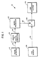
- the system 10 comprises a means for detecting the radiation output of a fire initiating device.
- a means for detecting the radiation output of a fire initiating device may be a log detector circuit 12 having a dynamic range in excess of 100db coupled to a radiation detecting means such as a photodiode having a spectral response between, typically, 0.7 to 1.0 micrometer.
- Detector 12 has an analog voltage output 14 coupled to the input of an analog-to-digital convertor 16.
- Analog-to-digital convertor 16 converts, in a well known manner, the voltage output 14 from detector 12 into a digital signal expressive of the voltage magnitude of the signal.
- This digital representation is expressed as a number of discrete bits which are conveyed by a data bus 18 for input to a control means which may be a data processing means, such as a microprocessor 20.
- a control means which may be a data processing means, such as a microprocessor 20.
- a data processing means such as a microprocessor 20.
- Microprocessor 20 has an inhibit output 22 coupled to a switching means 24.
- Switching means 24 is further coupled to the output 26 of a fire sensor 28.
- microprocessor 20 may open and close switching means 24, thereby connecting or disconnecting the output 26 of fire sensor 28.
- Switching means 24 may be a semiconductor switch or an electromagnetic relay or any suitable, fast-acting switch which is capable of being controlled by microprocessor 20.
- the output 26 of fire sensor 28 may be coupled to a suitable fire suppressant means 29 which is operable for suppressing or extinguishing a fire, such as a hydrocarbon fire arising from the explosion of a fuel tank within an armored vehicle.
- the fire suppressant system 29 may be a bank of CO2 or freon cylinders coupled to a fast acting activation mechanism.
- Fire sensor 28 may be sensitive to a specific one or ones of spectral lines associated with the combustion products of a hydrocarbon fire.
- microprocessor 20 In order to perform this valuable function of selectively inhibiting the output of fire sensor 28 after the entry of a HEAT round, the microprocessor 20 is operable for executing a number of software routines. In order to accomplish this function microprocessor 20 may be provided with memory devices and address and data buses (not shown) operable for accessing these memory devices in a manner which is well known to those skilled in the art.
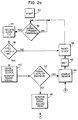
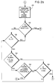
- FIGs. 2a and 2b there is shown in flow chart form some of the software routines which are executed by microprocesser 20 in accordance with the invention.
- microprocessor 20 After initial turn on of the system, indicated by the block 30, microprocessor 20 continuously monitors the output of detector 12 as indicated by the block 32. If the magnitude of the output of detector 12 is determined to be above a given threshold value, such as 0.5 volts, the microprocesser 20 initiates an internal timer to a zero count, at block 34. Thereafter the timer increments by, for example, being clocked with a signal having a known frequency. Thus, the value of the timer at any given time after initialization is related to the elapsed time since the detection of the entry of the round.
- a given threshold value such as 0.5 volts
- the dV/dT of the round signal is calculated at block 36.
- a comparison is also made at this time to determine if the calculated dV/dT is equal to or greater than a given threshold value, such as 2000 volts/second. If the dV/dT is found to exceed this threshold value the microprocessor 20 will inhibit the output of the fire sensor at block 40.
- a dV/dT having this rapid rate of rise has been found to be present generally only if the HEAT round has entered the vehicle without penetrating a fuel cell.
- the microprocessor 20 executes the software routine at block 38 which resets the clock and thereafter returns to the block 32 where the output signal of the detector 12 is continuous monitored.
- Fig. 3 there is shown a characteristic thermal profile, or signature, of a HEAT round which did not penetrate a fuel cell upon entry of the vehicle.
- the primary threshold level is exceeded in less than 100 microseconds, and the dV/dT is well in excess of 2000 volts/second for the next 300 microseconds.
- the occurrence of a round signature as depicted in Fig. 3 will result in the sensor's output signal being inhibited as in block 40 of Fig. 2.
- the thermal signature of a heat round which has penetrated a fuel cell upon entry of the vehicle is shown in Fig. 4.
- the output of the detector circuit does not reach the primary threshold until approximately 4.5 milliseconds after round penetration. This, by itself, would have given the fire sensor ample time to respond, but even after the round signal had exceeded the primary threshold level the sensor would not have been inhibited because of the slow rise of the dV/dT signal.
- the microprocessor 20 will continue to monitor the round signature and record the highest level reached.
- the reading from the analog-to-digital convertor 16 is compared to the highest reading prior to this time. If at this time the magnitude of the present level is determined to be less than a given secondary threshold value, such as 40% of the highest level recorded, the fire sensor output is enabled at block 44. This enables the sensor output for a round which has entered the vehicle without penetrating a fuel cell, but which did hit a fuel cell or other highly combustible material inside the vehicle. Such an occurrence is depicted in the graph of Fig. 5.
- the microprocessor 20 monitors the round detector output signal for an additional 3.25 milliseconds and records the peak value and the time of the occurrence of the peak value. After this time has lapsed, the microprocessor 20 performs a statistical analysis of the round signal. In order to perform this analysis, microprocessor 20 samples the round signal at approximately 100 microsecond intervals and calculates the mean value of the signal and the mean value of the prior 16 residuals of the signal
- the signal from the round detector should be decreasing unless a secondary fire has occurred.
- the slope of the round signal after this time is utilized to detect the occurrence of a secondary fire.
- the polarity of the value of the mean of the residuals is utilized to determine the value of the slope.
- the output of the fire sensor is enabled.
- the use of the value of the mean of the residuals allows for the detection of a rapid change in polarity at or near the peak energy level or levels received by the detector. It is at this point where the peak energy level or levels occurs that the chance of a secondary fire is greatest.
- the system automatically and continually adjusts the sensitivity in relation to the energy and slope of the round signal.
- Fig. 6 illustrates a round signature wherein a secondary fire has started
- Fig. 7 illustrates a detector signal which has a small secondary positive slope which results from a large number of inert round signatures.
- the magnitude of the received round signature signal must also be in excess of the primary threshold in order to enable the sensor.
- the current timer value is compared to the time at which the peak reading was recorded. After 4 milliseconds have elapsed since the time of peak intensity the round signal is compared to a secondary threshold level at block 54.
- This secondary threshold level is not a fixed level but, in accordance with the invention, is equal to the time of the peak reading plus 4.0 milliseconds times the value of the peak reading divided by a function of time, or where S ET is the secondary energy threshold, ⁇ is the time of peak energy of the round, V PEAK is the peak amplitude of the round in volts, and T is the current elapsed time relative to the entry of the round.
- This secondary level has an initial value equal to the value of peak intensity and is thereafter reduced as a function of time until it is equal to the primary threshold level.
- the signal is determined to be equal to or greater than the secondary threshold (block 54) the signal is compared to the primary threshold level. If the signal is found to also be greater than the primary threshold the fire sensor output is enabled at block 44. Thus, the sensor is enabled when there is a secondary fire but the round is cooled by the engulfing flame. Such an occurrence is depicted in the graph of Fig. 8. If the signal magnitude is determined to be less than either the secondary or primary threshold levels, blocks 54 and 56 respectively, the fire sensor is not enabled. The microprocessor 20 thereafter continues to compare the signal to the secondary level, the primary level, and check the polarity of the slope (block 50) for 500 milliseconds, at which time the sensor is once more enabled, at block 58.
- the use of the apparatus and method of the invention overcomes those problems of the prior art which have been previously described.
- the use of the invention does not require that the fire sensor be disabled because of the saturation of the round detector due to a HEAT round having an excessive thermal energy output.
- the use of the invention is also advantageous in that the secondary threshold level is not a fixed level, but instead is determined in a dynamic manner based in part upon the elapsed time from the entry of the HEAT round and the peak intensity of the entering HEAT round.
- the use of the invention does not require any type of special coding or calibration related to the type and/or thickness of the vehicle's armor.
- a system constructed in accordance with the apparatus and method of the invention may be advantageously employed in a wide variety of vehicles without requiring any special adaptation for that particular vehicle.
Landscapes
- Business, Economics & Management (AREA)
- Emergency Management (AREA)
- Physics & Mathematics (AREA)
- General Physics & Mathematics (AREA)
- Fire-Detection Mechanisms (AREA)
- Fire Alarms (AREA)
- Photometry And Measurement Of Optical Pulse Characteristics (AREA)
- Radiation Pyrometers (AREA)
Abstract
Claims (19)
- Un système détecteur d'incendie avec discrimination de projectile de type adaptatif, comprenant :
des moyens pour détecter l'apparition d'un incendie, ces moyens de détection d'incendie ayant un signal de sortie qui est destiné à activer un système d'extinction d'incendie lorsqu'un incendie est détecté, ce signal de sortie étant appliqué au système d'extinction d'incendie, avec possibilité de commutation, par des moyens de commutation que l'on peut actionner pour appliquer le signal de sortie au système d'extinction d'incendie et pour interrompre son application;
des moyens pour détecter le dégagement d'énergie d'un dispositif de déclenchement d'incendie, ces moyens de détection de dispositif ayant un signal de sortie qui exprime un niveau d'énergie thermique associée au dispositif; et
des moyens pour commander le fonctionnement des moyens de commutation, ces moyens de commande étant connectés fonctionnellement de façon à recevoir le signal de sortie des moyens de détection de dispositif, pour déterminer le niveau de l'énergie thermique du dispositif, caractérisé en ce que les moyens de commande sont en outre connectés fonctionnellement aux moyens de commutation pour interrompre l'application du signal d'activation d'extinction d'incendie lorsque la vitesse de variation du niveau de l'énergie thermique dépasse une valeur de seuil donnée, et, en outre, les moyens de commande appliquent à nouveau le signal d'activation d'extinction d'incendie, après un intervalle de temps donné, lorsque le niveau de l'énergie thermique a une valeur qui est inférieure à un pourcentage donné d'une valeur d'un niveau maximal qui est atteint par l'énergie thermique, pendant l'intervalle de temps donné. - Le système défini dans la revendication 1, dans lequel les moyens de détection de dispositif comprennent des moyens de détection de rayonnement ayant une réponse spectrale entre 0,7 et 1,0 micromètre, et un circuit détecteur logarithmique connecté aux moyens de détection de rayonnement, ce circuit détecteur logarithmique ayant une dynamique supérieure à 100 dB, et une tension de sortie qui exprime l'intensité du rayonnement reçu par les moyens de détection de rayonnement.
- Le système défini dans la revendication 2, dans lequel les moyens de commande sont des moyens de traitement de données capables de déterminer, à partir du niveau de la tension de sortie, l'intensité du rayonnement que reçoivent les moyens de détection de rayonnement.
- Le système défini dans la revendication 3, comprenant en outre des moyens de conversion analogique-numérique capables de convertir la tension de sortie en un ensemble de bits numériques pour l'application aux moyens de traitement de données.
- Le système défini dans la revendication 1, dans lequel la valeur de seuil donnée est de 2000 volts par seconde.
- Le système défini dans la revendication 1, dans lequel le pourcentage donné est de 40% et dans lequel l'intervalle de temps donné est de 1,75 milliseconde.
- Un procédé pour empêcher sélectivement le fonctionnement d'un système d'extinction d'incendie après la pénétration d'un projectile à haute énergie dans une enceinte ayant un système d'extinction d'incendie qui est normalement en fonction, comprenant les étapes suivantes :
on contrôle le signal de sortie d'un détecteur de projectile pour déterminer un instant auquel le signal de sortie dépasse une valeur de seuil primaire donnée représentative de l'énergie qui est associée à la pénétration d'un projectile;
on déclenche le fonctionnement d'un moyen de mesure de temps pour actualiser un temps écoulé lié à l'instant de pénétration du projectile;
on contrôle l'énergie du projectile pendant un premier intervalle de temps prédéterminé;
après le premier intervalle de temps prédéterminé, on calcule la vitesse d'augmentation de l'énergie associée au projectile;
on détermine si la vitesse d'augmentation calculée est supérieure ou égale à une première valeur prédéterminée;
on empêche le fonctionnement du système d'extinction d'incendie si la vitesse d'augmentation calculée est supérieure ou égale à la première valeur prédéterminée;
après avoir empêché le fonctionnement du système, on contrôle l'énergie du projectile pendant un second intervalle de temps prédéterminé;
on enregistre la valeur d'une énergie maximale qui est atteinte par le projectile pendant le second intervalle de temps prédéterminé;
on compare l'énergie du projectile à la fin du second intervalle de temps prédéterminé, et la valeur enregistrée;
on détermine si l'énergie du projectile à la fin du second intervalle de temps prédéterminé est inférieure à un pourcentage donné de la valeur enregistrée; et
on permet le fonctionnement du système d'extinction d'incendie si la détermination qui est faite indique que l'énergie est inférieure au pourcentage donné. - Le procédé de la revendication 7, dans lequel si la détermination qui est faite indique que l'énergie du projectile à la fin du second intervalle de temps prédéterminé est supérieure ou égale au pourcentage donné, on accomplit en outre les étapes suivantes :
on contrôle le signal de sortie du détecteur de projectile pendant un troisième intervalle de temps prédéterminé;
on enregistre la valeur de l'énergie maximale qui est atteinte par le projectile et l'instant auquel l'énergie maximale a été atteinte, pendant le troisième intervalle prédéterminé;
on échantillonne le signal de sortie du détecteur de projectile avec un intervalle d'échantillonnage donné, pour obtenir un nombre donné d'échantillons de ce signal de sortie;
on calcule la moyenne du signal de sortie et la moyenne des résidus du signal de sortie pour le nombre d'instants donné;
on détermine la polarité de la pente du signal de sortie à partir de la polarité de la moyenne des résidus; et
on détermine si le niveau du signal de sortie est supérieur ou égal au seuil primaire. - Le procédé de la revendication 8, dans lequel si on détermine que la pente du signal de sortie est positive et si le niveau du signal de sortie est supérieur ou égal au seuil primaire, on accomplit en outre l'étape suivante :
on permet le fonctionnement du système d'extinction d'incendie. - Le procédé de la revendication 8, dans lequel si on détermine que la pente du signal de sortie est négative, ou si on détermine que le niveau du signal de sortie est inférieur au seuil primaire, on accomplit en outre les étapes suivantes :
on compare l'instant courant et l'instant enregistré auquel l'énergie maximale a été atteinte; et
on détermine si l'instant courant est supérieur ou égal à l'instant enregistré augmenté d'un quatrième intervalle de temps prédéterminé. - Le procédé de la revendication 10, dans lequel si on détermine que l'instant courant est supérieur ou égal à l'instant enregistré augmenté du quatrième intervalle de temps prédéterminé, on accomplit en outre les étapes suivantes :
on calcule un niveau de seuil d'énergie secondaire;
on compare le niveau courant du signal de sortie du détecteur de projectile et le niveau de seuil d'énergie secondaire; et
on détermine si le niveau courant du signal de sortie du détecteur de projectile est supérieur ou égal au niveau de seuil secondaire calculé. - Le procédé de la revendication 11, dans lequel si on détermine que le niveau courant du signal de sortie du détecteur de projectile est supérieur ou égal au niveau d'énergie secondaire calculé, on accomplit en outre les étapes suivantes :
on détermine si le niveau courant du signal de sortie du détecteur de projectile est supérieur au niveau de seuil primaire, et si la détermination qui est faite indique que le niveau courant est supérieur au niveau de seuil primaire, on permet le fonctionnement du système d'extinction d'incendie. - Le procédé de la revendication 7, dans lequel on empêche le fonctionnement du système d'extinction d'incendie en déconnectant du système la sortie d'un détecteur d'incendie.
- Le procédé de la revendication 7, dans lequel chacune des étapes de contrôle comprend en outre l'étape suivante :
on détecte avec un circuit détecteur logarithmique ayant une tension de sortie, une intensité de rayonnement thermique qui est associée au projectile. - Le procédé de la revendication 14, dans lequel la valeur de seuil primaire est approximativement de 0,5 volt et dans lequel la première valeur prédéterminée est approximativement de 2000 volts par seconde.
- Le procédé de la revendication 10, dans lequel le premier intervalle de temps prédéterminé est approximativement de 300 microsecondes, dans lequel le second intervalle de temps prédéterminé est approximativement de 1,75 milliseconde, dans lequel le troisième intervalle de temps prédéterminé est approximativement de 3,25 millisecondes, et dans lequel le quatrième intervalle de temps prédéterminé est approximativement de 4,0 millisecondes.
- Le procédé de la revendication 7, dans lequel le pourcentage donné est approximativement de 40%.
- Le procédé de la revendication 8, dans lequel le nombre d'échantillons donné est approximativement de seize, et dans lequel l'intervalle d'échantillonnage donné est approximativement de 100 microsecondes.
- Le procédé de la revendication 11, dans lequel le niveau de seuil d'énergie secondaire est calculé conformément à l'expression :

SET est le seuil d'énergie secondaire,
τ est l'instant d'énergie de crête du projectile,
VCR est l'amplitude de crête du projectile, en volts, et
T est le temps écoulé courant à partir de la pénétration du projectile.
Applications Claiming Priority (2)
| Application Number | Priority Date | Filing Date | Title |
|---|---|---|---|
| US07/115,948 US4783592A (en) | 1987-11-02 | 1987-11-02 | Real time adaptive round discrimination fire sensor |
| US115948 | 1987-11-02 |
Publications (2)
| Publication Number | Publication Date |
|---|---|
| EP0343235A1 EP0343235A1 (fr) | 1989-11-29 |
| EP0343235B1 true EP0343235B1 (fr) | 1993-07-28 |
Family
ID=22364322
Family Applications (1)
| Application Number | Title | Priority Date | Filing Date |
|---|---|---|---|
| EP89900951A Expired - Lifetime EP0343235B1 (fr) | 1987-11-02 | 1988-10-11 | Detecteur d'incendie a discrimination de projectile adaptable en temps reel |
Country Status (11)
| Country | Link |
|---|---|
| US (1) | US4783592A (fr) |
| EP (1) | EP0343235B1 (fr) |
| JP (1) | JPH0727590B2 (fr) |
| KR (1) | KR910008687B1 (fr) |
| AU (1) | AU609936B2 (fr) |
| BR (1) | BR8807276A (fr) |
| CA (1) | CA1294021C (fr) |
| DE (1) | DE3882699T2 (fr) |
| IL (1) | IL88132A (fr) |
| NO (1) | NO175124C (fr) |
| WO (1) | WO1989004528A1 (fr) |
Families Citing this family (8)
| Publication number | Priority date | Publication date | Assignee | Title |
|---|---|---|---|---|
| EP0825573B2 (fr) * | 1996-08-19 | 2005-03-23 | Siemens Aktiengesellschaft | Procédé et dispositif d'analyse d'un signal d'un capteur de mouvements |
| US6261086B1 (en) | 2000-05-05 | 2001-07-17 | Forney Corporation | Flame detector based on real-time high-order statistics |
| AU2003225228A1 (en) | 2002-05-03 | 2003-11-17 | Donnelly Corporation | Object detection system for vehicle |
| US7690837B2 (en) * | 2006-03-07 | 2010-04-06 | The Boeing Company | Method of analysis of effects of cargo fire on primary aircraft structure temperatures |
| CN103218892B (zh) * | 2013-04-01 | 2015-09-02 | 深圳市广安消防装饰工程有限公司 | 可视频监视记录火灾及进行公共安全监控的火灾探测系统 |
| CN103218900B (zh) * | 2013-04-01 | 2016-04-20 | 深圳市广安消防装饰工程有限公司 | 可进行视频数据采集的自发光手动火灾报警按钮 |
| NO344162B1 (no) * | 2015-12-18 | 2019-09-23 | Froeystad As | Teine for fangst og oppbevaring av levende fisk |
| US12115398B2 (en) | 2022-07-13 | 2024-10-15 | The Boeing Company | System and method for controlling a fire suppression system of an aircraft |
Family Cites Families (8)
| Publication number | Priority date | Publication date | Assignee | Title |
|---|---|---|---|---|
| US3825754A (en) * | 1973-07-23 | 1974-07-23 | Santa Barbara Res Center | Dual spectrum infrared fire detection system with high energy ammunition round discrimination |
| GB1561303A (en) * | 1976-05-04 | 1980-02-20 | Amf Inc | Temerature control for rotary driers |
| US4101767A (en) * | 1977-05-20 | 1978-07-18 | Sensors, Inc. | Discriminating fire sensor |
| GB2079933B (en) * | 1980-07-12 | 1984-05-31 | Graviner Ltd | Improvements in and relating to fire and explosion detection and suppression |
| GB2089503B (en) * | 1980-12-12 | 1984-07-18 | Graviner Ltd | Fire and explosion detection |
| US4679156A (en) * | 1981-05-21 | 1987-07-07 | Santa Barbara Research Center | Microprocessor-controlled fire sensor |
| GB2103789B (en) * | 1981-08-20 | 1985-08-07 | Graviner Ltd | Fire and explosion detection and suppression |
| US4603255A (en) * | 1984-03-20 | 1986-07-29 | Htl Industries, Inc. | Fire and explosion protection system |
-
1987
- 1987-11-02 US US07/115,948 patent/US4783592A/en not_active Expired - Lifetime
-
1988
- 1988-10-11 EP EP89900951A patent/EP0343235B1/fr not_active Expired - Lifetime
- 1988-10-11 JP JP1500838A patent/JPH0727590B2/ja not_active Expired - Lifetime
- 1988-10-11 DE DE89900951T patent/DE3882699T2/de not_active Expired - Lifetime
- 1988-10-11 AU AU29068/89A patent/AU609936B2/en not_active Expired
- 1988-10-11 KR KR1019890701224A patent/KR910008687B1/ko not_active Expired
- 1988-10-11 WO PCT/US1988/003451 patent/WO1989004528A1/fr not_active Ceased
- 1988-10-11 BR BR888807276A patent/BR8807276A/pt not_active IP Right Cessation
- 1988-10-24 IL IL88132A patent/IL88132A/xx not_active IP Right Cessation
- 1988-11-01 CA CA000581853A patent/CA1294021C/fr not_active Expired - Lifetime
-
1989
- 1989-06-27 NO NO892671A patent/NO175124C/no unknown
Also Published As
| Publication number | Publication date |
|---|---|
| CA1294021C (fr) | 1992-01-07 |
| IL88132A (en) | 1991-06-10 |
| KR910008687B1 (ko) | 1991-10-19 |
| AU609936B2 (en) | 1991-05-09 |
| JPH02502048A (ja) | 1990-07-05 |
| NO892671L (no) | 1989-06-27 |
| NO175124C (no) | 1994-08-31 |
| JPH0727590B2 (ja) | 1995-03-29 |
| WO1989004528A1 (fr) | 1989-05-18 |
| KR890702168A (ko) | 1989-12-23 |
| DE3882699D1 (de) | 1993-09-02 |
| DE3882699T2 (de) | 1994-03-03 |
| NO175124B (no) | 1994-05-24 |
| AU2906889A (en) | 1989-06-01 |
| US4783592A (en) | 1988-11-08 |
| BR8807276A (pt) | 1990-03-01 |
| NO892671D0 (no) | 1989-06-27 |
| EP0343235A1 (fr) | 1989-11-29 |
Similar Documents
| Publication | Publication Date | Title |
|---|---|---|
| US4101767A (en) | Discriminating fire sensor | |
| US3825754A (en) | Dual spectrum infrared fire detection system with high energy ammunition round discrimination | |
| US4639598A (en) | Fire sensor cross-correlator circuit and method | |
| EP0159798B2 (fr) | Système de détection d'incendie et d'explosion | |
| US4414542A (en) | Two channel comparison-type fire or explosion detecting system | |
| EP0343235B1 (fr) | Detecteur d'incendie a discrimination de projectile adaptable en temps reel | |
| JPS6148728A (ja) | マイクロプロセツサ制御の火災探知システム | |
| US4765413A (en) | Fire and explosion detection apparatus | |
| US4472715A (en) | Dual spectrum fire sensor with discriminator | |
| US4421984A (en) | Fire and explosion detection and suppression | |
| EP0073111B1 (fr) | Détection et suppression d'incendie et d'explosion | |
| US4469944A (en) | Optical discriminating fire sensor | |
| US4357534A (en) | Fire and explosion detection | |
| EP0066952A2 (fr) | Système de détection pour incendie ou explosion | |
| US4373136A (en) | Fire and explosion detection | |
| GB2067749A (en) | Improvements in and Relating to Fire and Explosion Detection | |
| GB2126713A (en) | Improvements in and relating to fire and explosion detection | |
| CA1172722A (fr) | Detection des feux et explosions | |
| GB2103789A (en) | Fire and explosion detection and suppression |
Legal Events
| Date | Code | Title | Description |
|---|---|---|---|
| PUAI | Public reference made under article 153(3) epc to a published international application that has entered the european phase |
Free format text: ORIGINAL CODE: 0009012 |
|
| 17P | Request for examination filed |
Effective date: 19890606 |
|
| AK | Designated contracting states |
Kind code of ref document: A1 Designated state(s): BE DE FR GB IT NL SE |
|
| 17Q | First examination report despatched |
Effective date: 19911107 |
|
| GRAA | (expected) grant |
Free format text: ORIGINAL CODE: 0009210 |
|
| AK | Designated contracting states |
Kind code of ref document: B1 Designated state(s): BE DE FR GB IT NL SE |
|
| REF | Corresponds to: |
Ref document number: 3882699 Country of ref document: DE Date of ref document: 19930902 |
|
| ET | Fr: translation filed | ||
| ITF | It: translation for a ep patent filed | ||
| PLBE | No opposition filed within time limit |
Free format text: ORIGINAL CODE: 0009261 |
|
| STAA | Information on the status of an ep patent application or granted ep patent |
Free format text: STATUS: NO OPPOSITION FILED WITHIN TIME LIMIT |
|
| 26N | No opposition filed | ||
| PGFP | Annual fee paid to national office [announced via postgrant information from national office to epo] |
Ref country code: NL Payment date: 19941031 Year of fee payment: 7 |
|
| EAL | Se: european patent in force in sweden |
Ref document number: 89900951.8 |
|
| PGFP | Annual fee paid to national office [announced via postgrant information from national office to epo] |
Ref country code: SE Payment date: 19950918 Year of fee payment: 8 |
|
| PGFP | Annual fee paid to national office [announced via postgrant information from national office to epo] |
Ref country code: BE Payment date: 19950925 Year of fee payment: 8 |
|
| PG25 | Lapsed in a contracting state [announced via postgrant information from national office to epo] |
Ref country code: NL Effective date: 19960501 |
|
| NLV4 | Nl: lapsed or anulled due to non-payment of the annual fee |
Effective date: 19960501 |
|
| PG25 | Lapsed in a contracting state [announced via postgrant information from national office to epo] |
Ref country code: SE Effective date: 19961012 |
|
| PG25 | Lapsed in a contracting state [announced via postgrant information from national office to epo] |
Ref country code: BE Effective date: 19961031 |
|
| BERE | Be: lapsed |
Owner name: SANTA BARBARA RESEARCH CENTER Effective date: 19961031 |
|
| EUG | Se: european patent has lapsed |
Ref document number: 89900951.8 |
|
| REG | Reference to a national code |
Ref country code: FR Ref legal event code: TP |
|
| REG | Reference to a national code |
Ref country code: GB Ref legal event code: IF02 |
|
| PGFP | Annual fee paid to national office [announced via postgrant information from national office to epo] |
Ref country code: GB Payment date: 20070918 Year of fee payment: 20 |
|
| PGFP | Annual fee paid to national office [announced via postgrant information from national office to epo] |
Ref country code: DE Payment date: 20071031 Year of fee payment: 20 |
|
| PGFP | Annual fee paid to national office [announced via postgrant information from national office to epo] |
Ref country code: IT Payment date: 20071012 Year of fee payment: 20 |
|
| PGFP | Annual fee paid to national office [announced via postgrant information from national office to epo] |
Ref country code: FR Payment date: 20071004 Year of fee payment: 20 |
|
| REG | Reference to a national code |
Ref country code: GB Ref legal event code: PE20 Expiry date: 20081010 |
|
| PG25 | Lapsed in a contracting state [announced via postgrant information from national office to epo] |
Ref country code: GB Free format text: LAPSE BECAUSE OF EXPIRATION OF PROTECTION Effective date: 20081010 |