EP0343237B1 - Taster-wechsel-vorrichtung - Google Patents
Taster-wechsel-vorrichtung Download PDFInfo
- Publication number
- EP0343237B1 EP0343237B1 EP89901076A EP89901076A EP0343237B1 EP 0343237 B1 EP0343237 B1 EP 0343237B1 EP 89901076 A EP89901076 A EP 89901076A EP 89901076 A EP89901076 A EP 89901076A EP 0343237 B1 EP0343237 B1 EP 0343237B1
- Authority
- EP
- European Patent Office
- Prior art keywords
- holder
- sensing device
- magazine
- support elements
- support
- Prior art date
- Legal status (The legal status is an assumption and is not a legal conclusion. Google has not performed a legal analysis and makes no representation as to the accuracy of the status listed.)
- Expired - Lifetime
Links
- 230000033001 locomotion Effects 0.000 claims abstract description 49
- 230000008878 coupling Effects 0.000 claims description 14
- 238000010168 coupling process Methods 0.000 claims description 14
- 238000005859 coupling reaction Methods 0.000 claims description 14
- 238000000034 method Methods 0.000 claims description 9
- 230000000694 effects Effects 0.000 claims description 5
- 230000000717 retained effect Effects 0.000 claims description 4
- 241001422033 Thestylus Species 0.000 abstract description 54
- 239000000523 sample Substances 0.000 abstract description 14
- 230000004048 modification Effects 0.000 description 11
- 238000012986 modification Methods 0.000 description 11
- 230000006835 compression Effects 0.000 description 5
- 238000007906 compression Methods 0.000 description 5
- 238000006073 displacement reaction Methods 0.000 description 4
- 239000000428 dust Substances 0.000 description 4
- 238000013519 translation Methods 0.000 description 4
- 230000014616 translation Effects 0.000 description 4
- 230000008901 benefit Effects 0.000 description 3
- 230000008859 change Effects 0.000 description 3
- 239000012636 effector Substances 0.000 description 3
- 238000005259 measurement Methods 0.000 description 3
- 230000007246 mechanism Effects 0.000 description 3
- 230000009471 action Effects 0.000 description 2
- 238000013461 design Methods 0.000 description 2
- 238000007689 inspection Methods 0.000 description 2
- 238000011068 loading method Methods 0.000 description 2
- 230000008569 process Effects 0.000 description 2
- 238000013459 approach Methods 0.000 description 1
- 238000010276 construction Methods 0.000 description 1
- 239000000356 contaminant Substances 0.000 description 1
- 238000000151 deposition Methods 0.000 description 1
- 230000000994 depressogenic effect Effects 0.000 description 1
- 230000007274 generation of a signal involved in cell-cell signaling Effects 0.000 description 1
- 230000002452 interceptive effect Effects 0.000 description 1
- 230000004044 response Effects 0.000 description 1
- 238000012546 transfer Methods 0.000 description 1
Images





Classifications
-
- B—PERFORMING OPERATIONS; TRANSPORTING
- B25—HAND TOOLS; PORTABLE POWER-DRIVEN TOOLS; MANIPULATORS
- B25J—MANIPULATORS; CHAMBERS PROVIDED WITH MANIPULATION DEVICES
- B25J15/00—Gripping heads and other end effectors
- B25J15/04—Gripping heads and other end effectors with provision for the remote detachment or exchange of the head or parts thereof
- B25J15/0491—Gripping heads and other end effectors with provision for the remote detachment or exchange of the head or parts thereof comprising end-effector racks
-
- B—PERFORMING OPERATIONS; TRANSPORTING
- B23—MACHINE TOOLS; METAL-WORKING NOT OTHERWISE PROVIDED FOR
- B23Q—DETAILS, COMPONENTS, OR ACCESSORIES FOR MACHINE TOOLS, e.g. ARRANGEMENTS FOR COPYING OR CONTROLLING; MACHINE TOOLS IN GENERAL CHARACTERISED BY THE CONSTRUCTION OF PARTICULAR DETAILS OR COMPONENTS; COMBINATIONS OR ASSOCIATIONS OF METAL-WORKING MACHINES, NOT DIRECTED TO A PARTICULAR RESULT
- B23Q3/00—Devices holding, supporting, or positioning work or tools, of a kind normally removable from the machine
- B23Q3/155—Arrangements for automatic insertion or removal of tools, e.g. combined with manual handling
- B23Q3/1552—Arrangements for automatic insertion or removal of tools, e.g. combined with manual handling parts of devices for automatically inserting or removing tools
- B23Q3/15553—Tensioning devices or tool holders, e.g. grippers
-
- B—PERFORMING OPERATIONS; TRANSPORTING
- B43—WRITING OR DRAWING IMPLEMENTS; BUREAU ACCESSORIES
- B43L—ARTICLES FOR WRITING OR DRAWING UPON; WRITING OR DRAWING AIDS; ACCESSORIES FOR WRITING OR DRAWING
- B43L13/00—Drawing instruments, or writing or drawing appliances or accessories not otherwise provided for
- B43L13/02—Draughting machines or drawing devices for keeping parallelism
- B43L13/022—Draughting machines or drawing devices for keeping parallelism automatic
- B43L13/024—Drawing heads therefor
-
- G—PHYSICS
- G01—MEASURING; TESTING
- G01B—MEASURING LENGTH, THICKNESS OR SIMILAR LINEAR DIMENSIONS; MEASURING ANGLES; MEASURING AREAS; MEASURING IRREGULARITIES OF SURFACES OR CONTOURS
- G01B21/00—Measuring arrangements or details thereof, where the measuring technique is not covered by the other groups of this subclass, unspecified or not relevant
- G01B21/02—Measuring arrangements or details thereof, where the measuring technique is not covered by the other groups of this subclass, unspecified or not relevant for measuring length, width, or thickness
- G01B21/04—Measuring arrangements or details thereof, where the measuring technique is not covered by the other groups of this subclass, unspecified or not relevant for measuring length, width, or thickness by measuring coordinates of points
- G01B21/047—Accessories, e.g. for positioning, for tool-setting, for measuring probes
-
- G—PHYSICS
- G01—MEASURING; TESTING
- G01B—MEASURING LENGTH, THICKNESS OR SIMILAR LINEAR DIMENSIONS; MEASURING ANGLES; MEASURING AREAS; MEASURING IRREGULARITIES OF SURFACES OR CONTOURS
- G01B5/00—Measuring arrangements characterised by the use of mechanical techniques
- G01B5/004—Measuring arrangements characterised by the use of mechanical techniques for measuring coordinates of points
- G01B5/008—Measuring arrangements characterised by the use of mechanical techniques for measuring coordinates of points using coordinate measuring machines
- G01B5/012—Contact-making feeler heads therefor
-
- Y—GENERAL TAGGING OF NEW TECHNOLOGICAL DEVELOPMENTS; GENERAL TAGGING OF CROSS-SECTIONAL TECHNOLOGIES SPANNING OVER SEVERAL SECTIONS OF THE IPC; TECHNICAL SUBJECTS COVERED BY FORMER USPC CROSS-REFERENCE ART COLLECTIONS [XRACs] AND DIGESTS
- Y10—TECHNICAL SUBJECTS COVERED BY FORMER USPC
- Y10T—TECHNICAL SUBJECTS COVERED BY FORMER US CLASSIFICATION
- Y10T483/00—Tool changing
- Y10T483/10—Process
-
- Y—GENERAL TAGGING OF NEW TECHNOLOGICAL DEVELOPMENTS; GENERAL TAGGING OF CROSS-SECTIONAL TECHNOLOGIES SPANNING OVER SEVERAL SECTIONS OF THE IPC; TECHNICAL SUBJECTS COVERED BY FORMER USPC CROSS-REFERENCE ART COLLECTIONS [XRACs] AND DIGESTS
- Y10—TECHNICAL SUBJECTS COVERED BY FORMER USPC
- Y10T—TECHNICAL SUBJECTS COVERED BY FORMER US CLASSIFICATION
- Y10T483/00—Tool changing
- Y10T483/17—Tool changing including machine tool or component
- Y10T483/1733—Rotary spindle machine tool [e.g., milling machine, boring, machine, grinding machine, etc.]
- Y10T483/1736—Tool having specific mounting or work treating feature
-
- Y—GENERAL TAGGING OF NEW TECHNOLOGICAL DEVELOPMENTS; GENERAL TAGGING OF CROSS-SECTIONAL TECHNOLOGIES SPANNING OVER SEVERAL SECTIONS OF THE IPC; TECHNICAL SUBJECTS COVERED BY FORMER USPC CROSS-REFERENCE ART COLLECTIONS [XRACs] AND DIGESTS
- Y10—TECHNICAL SUBJECTS COVERED BY FORMER USPC
- Y10T—TECHNICAL SUBJECTS COVERED BY FORMER US CLASSIFICATION
- Y10T483/00—Tool changing
- Y10T483/17—Tool changing including machine tool or component
- Y10T483/1733—Rotary spindle machine tool [e.g., milling machine, boring, machine, grinding machine, etc.]
- Y10T483/179—Direct tool exchange between spindle and matrix
- Y10T483/1793—Spindle comprises tool changer
-
- Y—GENERAL TAGGING OF NEW TECHNOLOGICAL DEVELOPMENTS; GENERAL TAGGING OF CROSS-SECTIONAL TECHNOLOGIES SPANNING OVER SEVERAL SECTIONS OF THE IPC; TECHNICAL SUBJECTS COVERED BY FORMER USPC CROSS-REFERENCE ART COLLECTIONS [XRACs] AND DIGESTS
- Y10—TECHNICAL SUBJECTS COVERED BY FORMER USPC
- Y10T—TECHNICAL SUBJECTS COVERED BY FORMER US CLASSIFICATION
- Y10T483/00—Tool changing
- Y10T483/18—Tool transfer to or from matrix
- Y10T483/1818—Matrix including means to project tool for transfer
-
- Y—GENERAL TAGGING OF NEW TECHNOLOGICAL DEVELOPMENTS; GENERAL TAGGING OF CROSS-SECTIONAL TECHNOLOGIES SPANNING OVER SEVERAL SECTIONS OF THE IPC; TECHNICAL SUBJECTS COVERED BY FORMER USPC CROSS-REFERENCE ART COLLECTIONS [XRACs] AND DIGESTS
- Y10—TECHNICAL SUBJECTS COVERED BY FORMER USPC
- Y10T—TECHNICAL SUBJECTS COVERED BY FORMER US CLASSIFICATION
- Y10T483/00—Tool changing
- Y10T483/18—Tool transfer to or from matrix
- Y10T483/1818—Matrix including means to project tool for transfer
- Y10T483/1836—Pivoting
-
- Y—GENERAL TAGGING OF NEW TECHNOLOGICAL DEVELOPMENTS; GENERAL TAGGING OF CROSS-SECTIONAL TECHNOLOGIES SPANNING OVER SEVERAL SECTIONS OF THE IPC; TECHNICAL SUBJECTS COVERED BY FORMER USPC CROSS-REFERENCE ART COLLECTIONS [XRACs] AND DIGESTS
- Y10—TECHNICAL SUBJECTS COVERED BY FORMER USPC
- Y10T—TECHNICAL SUBJECTS COVERED BY FORMER US CLASSIFICATION
- Y10T483/00—Tool changing
- Y10T483/19—Miscellaneous
Definitions
- This invention relates to apparatus for changing a sensing device in a positioning machine, such as a coordinate measuring machine, machine tool or inspection robot.
- Such positioning machines comprise a holder, to which a sensing device is coupleable, and which is movable relative to a magazine in which the sensing device is contained.
- the coupling means is in the form of a bayonet joint
- the holder includes a motor for rotating the holder relative to the sensing device stored in the magazine, in order to actuate the bayonet joint.
- This arrangement requires a motor in the holder.
- the motor increases the mass of the holder, so that the positioning machine is more subject to inertial deflections when the holder is accelerated. Since such deflections reduce the accuracy of e.g. measurement, the mass of the holder is one of the limiting factors on the speed at which measurements can be made.
- apparatus for changing a sensing device in a positioning machine comprising: a magazine having means for releasably supporting the sensing device in a stored position; a holder which is capable of translational movement by the positioning machine, relative to the magazine and to a workpiece, for removal of the sensing device from the magazine, performance of a sensing operation on the workpiece, and return of the sensing device to the magazine; means for releasably coupling the sensing device to the holder, comprising first support elements provided on the holder, second support elements provided on the sensing device and engageable with the first support elements, and releasable bias means for urging the first and second support elements into engagement with each other; and means operable relative movement between the holder and the sensing device in the magazine for actuating the coupling means between a coupled state (in which the bias means urge the first and second support elements into engagement with each other) and an uncoupled state (in which the bias means are released and the holder is
- a second aspect of the present invention provides a method of releasably coupling a sensing device retained in a magazine on a pivotal support, to a holder supported by a positioning machine for movement relative to the magazine, wherein the sensing device and holder are coupled by relative rotation, the method comprising the steps of: moving the holder to a predetermined position relative to the sensing device; with the sensing device retained in the magazine, translating the holder and sensing device together, thereby to cause the support to pivot, the sensing device to rotate relative to the holder and to effect coupling between the sensing device and the holder; and with the sensing device coupled to the holder, translating the holder to remove the sensing device from the magazine.
- Fig. 1 is an elevation of a positioning machine including the connecting mechanisms.
- Fig. 2 is a view on the line II-II in Fig. 1.
- Fig. 3 is an enlarged detail of Fig. 2.
- Fig. 4 is a section on the line IV-IV in Fig. 3.
- Fig. 5 is a section on the line V-V in Fig. 3.
- Fig. 6 is a view similar to Fig. 4 but shows a first modification.
- Fig. 7 is a section on the line VII-VII in Fig. 6 and shows different operational positions.
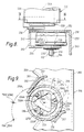
- Fig. 8 is view similar to Fig. 6 but shows a second modification and shows a first operational position.
- Fig. 9 is a section on the line IX-IX in Fig. 8.
- Fig.10 is a view similar to Fig. 8 but shows a second operational position.
- Fig.11 is a section on the line XI-XI in Fig. 10.
- Fig.12 is a view similar to Fig. 10 but shows a third operational position.
- Fig.13 is a section on the line XIII-XIII in Fig. 12.
- Fig.14 is an elevation of a further positioning machine.
- Fig.15 is a section on the line XV-XV in Fig.14.
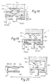
- Fig 16 is an enlarged detail of Fig.14 and shows a first operational position.
- Fig.17 is a section on the line XVII-XVII in Fig.16.
- Figs.18.19 and 20 show respectively a second, third and fourth operational position of the device of Fig.16.
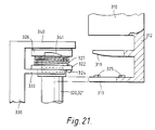
- Fig.21 is a view similar to Fig.16 but shows a modification.
- Fig.22 is a vertical section of another modification of the device of Fig.16.
- Fig.23 is a section on the line XXIII-XXIII in Fig.22.
- Fig. 1 shows a coordinate measuring machine having an arm member or quill 11 supported for translational motion only in the X,Y and Z-direction of the orthogonal coordinate system.
- the arm member or quill 11 is a vertically disposed elongate member, supported for longitudinal motion in the Z-direction in a bearing 12 integral with a carriage 13 supported for motion in the X-direction along a beam 14 itself supported for motion in the Y-direction on a track 15 mounted on a table 16 on which a workpiece 17 to be measured is supported.
- the member 11, carriage 13 and beam 14 are adapted to be driven translationally by motors (not shown) through any preselected linear or curved path under the control of an appropriately programmed computer (not shown), this being well-understood per se.
- Measurements are performed by means of a probe unit 10 having an axis 10A and comprising a holding unit 20 and a stylus unit 19.
- the holding unit is secured to the member 11.
- the stylus unit 19 is one of a number of such units adapted for different measuring operations and held in a magazine 18 supported on the table 16.
- the computer is programmed to drive the member 11 to perform measuring operations and to transfer any one of the units 19 between the holding unit 20 and the magazine 18.
- the unit 19 comprises a stylus 21 and a first connecting member 22.
- the holding unit 20 comprises a second connecting member 23 engageable with the member 22.
- the member 22 comprises a disc-shaped head 24 and three cylindrical arms 25 extending radially outwardly from the head 24 and being equi-spaced at 120° (Fig. 3).
- the arms 25 define open spaces 25B angularly therebetween.
- the member 23 comprises housing 26 which is open at its bottom end except for three inwardly extending flanges 29. Each flange has secured thereto a pair of spherical supports 30 defining between them a pair of converging surfaces 30A (Fig.3).
- the pairs of supports 30 are also equi-spaced at 120 degrees about the axis 10A.
- the flanges 29 are discontinuous so as to define an open space 30B angularly between each two pairs of supports 30.
- the supports 30 and arms 25 define first and second support elements respectively.
- the upper end of the housing 26 has secured thereto one end of a compression spring 31 (Fig. 4).
- the other end of the spring 31 has secured thereto a pressure member 31A terminating at a pointed end 31B.
- Figs. 1 and 4 show the units 19,20 in the disengaged condition but in alignment on the axis 10A.
- the unit 19 is supported (Figs. 3 and 4) on a surface 33 of an arm 35 of the magazine 18.
- the quill is lowered so that the elements 25,30 pass through the spaces 30B,25B (position 35B, Fig. 3) and the end 31B abuts the bottom of a conical recess 24A (Fig. 4) in the top of the head 24. Further lowering of the quill 11 compresses the spring 31 and brings the arms 25 into a position above the level of the spherical supports 30.
- the units 19,20 are then rotated, one relative to the other, through 60° to bring the arms 25 into axial alignment with the respective pairs of convergent surfaces 30A, and the quill 11 is raised again whereby the spring 31 becomes free to urge the head 24 downward and thereby resiliently urge the arms 25 into engagement which the surfaces 30A.
- the arms 25 and convergent surfaces 30A constitute a kinematic support means ensuring, in cooperation with the spring 31, that the units 19,20 are located against relative displacement transversely to and rotationally about the axis 10A, this condition being referred as the "rest position" of the stylus 21.
- the magazine 18 For the purpose of rotating the units 19, the magazine 18 comprises a plurality of said arms 35 each supported on a frame 36 for pivotal motion about a respective axis 35A extending in the Z-direction.
- the arms are connected by a link 37 so as to be moveable in mutually parallel relationship, though this link can be omitted if the arms 35 are sufficiently spaced apart.
- Detent means (not shown) are provided for locating the arms 35 with a light force at the position 35B and a further position 35C, (Fig.3).
- the positions 35B,35C define between them an angle W of 60°.
- Each arm 35 has a slot 32 in which the unit 19 is supportable against rotation relative to the arm so as to maintain the required orientation of the unit 19 relative to the supports 30.
- the pivotal motion of the arms 19 is effected by operation of the machine to cause translational movement of the quill through 60° of an arc 11A about the axis 35A of the relevant arm 35. This causes said relative rotation between the units 19,20 such that, on completion of the movement of the quill the elements 25,30 are in alignment in the Z-direction as shown at position 35C.
- the quill is then raised whereby the elements 25,30 come into engagement and the unit 19 becomes seated on the elements 30.
- the unit 19 can be returned to the magazine 18 by the reverse of the operations described.
- the latter can then be used for measuring the workpiece 17 by the process of moving the quill 11 to engage the stylus 21 with any selected surface of the workpiece.
- the engagement generates a signal 39 (Fig. 3), and the position of said surface is determined from a reading of the position of the quill relative to a pre-selected datum at the instant of the signal 39.
- the signal 39 may be generated by connecting the supports 30 in an electric circuit 38 capable of being closed by the arms 25, the signal being generated when one or more of the arms 25 are displaced from the relevant supports 30 when, on engagement with the workpiece, the stylus is displaced from its rest position.
- the piezo-electric or other force-sensitive element 40 may be provided on the pressure member 31A for generating the signal 39 in response to the sound wave produced in the stylus on engagement with the workpiece.
- the unit 19 includes a cup-shaped seal element 42 having an annular wall 42A forming a seal 41 (Fig. 5) with an annular groove 43 of the unit 20 thereby to protect the elements 25,30 against ingress of dust into the housing 26.
- FIG. 6 and 7 there is shown a mechanism similar to that shown in Figures 1 to 5 but modified to provide protection of the stylus unit while in position in the magazine.
- Like parts are given like reference numerals preceded by the numeral 1.
- a stylus unit 119 having arms 125 protected by an annular wall 142, and a holding unit 120 having supports 130 inside a housing 126 which, in this case, has a cylindrical exterior.
- the magazine here denoted 118, has in respect of each unit 119 a lower arm 135 for the support of the unit 119.
- the modification is as follows.
- the arm 135 is supported for pivotal motion about an axis 135A by means of a shaft 150 arranged in a bearing 151 provided on the magazine 118.
- the arrangement is such that in the stored position of the unit 119 in the magazine, the arm 135 has a position 135D (Fig. 7) such that the unit 119 is situated wholly beneath a horizontally diposed panel 152 of the magazine, and the arms 125 of the unit 119 are protected by the panel 152.
- the upper edges of the wall 142 form a seal 153 with the underside of the panel 152 against the ingress of dust.
- the unit 119 is supported on a surface 133 of the arm 115 while a cylindrical portion 134 of the unit 119 is in engagement with an open-ended slot 132 of the arm 115.
- a short pin 154 engages with a hole 155 to prevent rotation of the unit 119 relative to the arm 135.
- the shaft 150 has secured thereto an upper arm 156 which is generally parallel to the lower arm 135.
- the arm 156 comprises an open-ended slot 157 dimensioned to receive the outside of the housing 126 in a position in which the units 119,120 are in alignment on the axis 10A.
- the computer is programmed to lower the member 11 translationally along the axis 10A into engagement with the slot 157 and thereafter move the member 11 translationally through an arc 111A sufficient for to bring the unit 119, which necessarily accompanies the movement of the arm 156, from the position 135D into a position 135B in which the unit 119 is clear of the panel 152.
- the member 11 is then further lowered.
- the housing 126 slides through the slot 157 into a position in which the supports 130 are below the level of the arms 125.
- the member 11 may be moved along chords 111B,111C to effect the pivotal motion of the arm 135 and, in the case of the chord 111C, to effect the relative rotation of the units 119,120.
- a manoeuvre requires the unit 120 to slide relative to the arm 156, and the slot 157 must be made sufficiently long to accommodate such sliding.
- the unit 119 has to slide along the slot 132 and the latter has to be sufficiently long to accommodate the sliding movement of the portion 132, the hole 155 being dispensed with and the pin 154 being adapted to slide along the appropriately extended slot 132.
- the member 11 is used to perform two functions, viz. firstly, moving the arm 135 between the positions 135D,135B for the purpose of moving the unit 119 out of and into the protected position below the panel 152 and, secondly, moving the arm 135 between the positions 135B,135C for the purpose of relatively rotating the units 119,120 for effecting their engagement or disengagement.
- These two functions may be carried out separately.
- the first function i.e. the movement between the positions 135D,135B, may be carried out by a solenoid or other motor device because here no relative rotation between the units 119,120 is of significance.
- the operation of engaging or disengaging the units 19,119;20,120 is effected solely by translational movement of the member 11, i.e. by means of the motors already provided for moving the member 11 for measuring purposes, so that no additional electrical devices are required for effecting said engagement or disengagement.
- the magazine may store one or more probe units, i.e. units 110 each embodying a pair of units 119,120 in a state of engagement, and where each unit 110 has further arms similar to the arms 125 for engagement with the supports 130 by manoeuvres similar to the movement of the member 11 between the positions 135D,135B,135C or 135B,135C.
- probe units i.e. units 110 each embodying a pair of units 119,120 in a state of engagement, and where each unit 110 has further arms similar to the arms 125 for engagement with the supports 130 by manoeuvres similar to the movement of the member 11 between the positions 135D,135B,135C or 135B,135C.
- FIG. 8 to 13 there is shown a mechanism similar to that shown in Figures 6 and 7 but showing a further or second modification. Like parts are given like reference numerals preceded by the numeral 2.
- the stylus unit 219 includes a stylus 221 and three extensions or arms 225 extending radially from the axis 19A.
- the arms 225 are formed by the corner portions of a triangular plate 224, and each has a spherical support element 225A on its underside. The corner portions act to cover and protect the elements 225A from dirt and damage.
- the unit 219 also includes a cup-shaped seal element 242.
- the holding unit 220 includes a circular plate 229, and a housing 226 whose exterior is cylindrical at least at the lower end portion thereof.
- Three symmetrically spaced supports 230 are provided on the plate 229 in the form of three V-grooves extending radially from the axis 20A and engageable kinematically by the respective elements 225A.
- the plate 229 has, at its centre, a triangular cut-out 229A the corner portions of which define open spaces between each pair of V-grooves 230 so that the arms 225 can pass through this cut-out in operation.
- the upper end of the housing 226 has secured thereto one end of a compression spring 231.
- the other end of the spring 231 has secured thereto a pressure member 231A terminating at a pointed end 231B for engagement with the plate 224 to urge the elements 225A resiliently into engagement with the grooves 230.
- the magazine here denoted 218 has, in respect of each unit 219 to be stored therein, a lower arm 235 on which the unit 219 is supportable.
- Each arm 235 is supported for pivotal motion about an axis 235A of a shaft 250 arranged in a bearing 251 provided on the magazine 218.
- the arrangement is such that in the stored position of the unit 219 in the magazine, the arm 235 has a position such that the unit 219 is situated wholly beneath a horizontally disposed panel 252 of the magazine (Figs. 8,9), and the arms 225 of the unit 219 are protected by the panel 252.
- the free edges of the cup-shaped seal element 242 form a seal 253 with the underside of the panel 252 against the ingress of dust.
- the unit 219 is supported on a surface 233 of the arm 235 while a neck 234 of the unit 219 is in engagement with an open-ended slot 232 of the arm 235.
- the neck 234 has parallel sides 254 which engage the slot 232 in a manner preventing rotation of the unit 219 relative to the arm 235.
- each shaft 250 has secured thereto an upper arm 256 which is generally parallel to the lower arm 235 (as seen in Fig. 8) and which comprises an open-ended slot 257 dimensioned to receive the outside of the housing 226 in a manner permitting rotation of the arm 256 relative to the housing 226.
- the arms 235,256 are movable jointly about the axis 235A. Relevant angular positions of the arm 235 during such movement and the corresponding positions of the unit 219, are denoted 19A1,19A2,19A3. The corresponding positions of the arm 256 and of the unit 220 are denoted 20A1,20A2,20A3.
- the computer For the purpose of engaging the unit 220 with the unit 219, the computer is programmed to lower the member 11 along the axis 20A into engagement with the slot 257 at the position 20A3, as seen in Figs. 8 and 9. Thereafter, it translates the unit 220 linearly, firstly between the positions 20A3 and 20A2 (Figs. 10,11) and then between the positions 20A2 and 20A1 (Figs. 12,13). During those translations the housing 226 co-operates with the slot 257 to rotate the arm 256 and thereby rotate the arm 235 to move the unit 219 supported thereon through an arc 211A between the positions 19A3,19A2 and 19A1 respectively.
- the directions of the translations between the positions 20A3,20A2 and 20A2,20A1 are aligned to the x and y directions of the translational motions of the machine (Fig. 1) so that the movement of the arm 235 can be effected conveniently by simple operation of the machine.
- the positions 19A3,20A3 it does not matter whether the axes 19A,20A are in aligment but the arrangement is such that in the positions 19A2,20A2 and 19A1,20A1 the axes 19A,20A are in alignment.
- the unit 19 is moved from under the panel 252 into a position confronting the unit 220 (Figs. 10,11).
- the member 11 is then further lowered so that the housing 226 slides through the slot 257 into a position in which the supports 230 are below the level of the arms 225.
- linear movement of the member 11 to translate the unit 220 from the position 20A2 to the position 20A1 causes the arm 235 to rotate through 45° relative to the unit 220 with the result that the arms 225 attain a position of vertical alignment with the supports 230 (Figs. 12,13).
- the member 11 is raised to engage the arms 225 and supports 230.
- the unit 219 is now free to be removed from the arm 235 by movement of the member 11 in a direction out of the slots 232,256.
- the seal member 242 is received with a substantial gap in an annular groove 243 in the housing 226, in order form a seal while still permitting the stylus unit 219 to tilt.
- the stylus 221 is displaceable relative to the plate 229 in directions ⁇ X, ⁇ Y and +Z, such displacements being accommodated by tilting of the plate 224 on the plate 229 or by axial translation of the plate 224 towards the housing 226, all these displacements being accommodated by compression of the spring 231.
- the stylus is also displaceable in the -Z direction. This is achieved by the virtue of the plate 229 being supported on the housing 226 by three spherical elements 226A secured to the housing 226 and engaged respectively by three further V-grooves 229B in the plate 229.
- the grooves 229B are symmetrically spaced with respect to each other about the axis 20A, and angularly spaced from the grooves 230.
- the plate 229 is urged resiliently into the position of engagement with the elements 226A by three tension springs 258 (only one visible in Fig. 10) connected between the plate 229 and the housing 226.
- the -Z displacement is accommodated by extension of the springs 258.
- the pressure member 231A has an upwardly extending spigot 280, the top of which is displaceably steadied by a diaphragm 281.
- the spigot contains a lens 284 for focussing light from a light emitting diode 283 onto a photodetector 282.
- the magazine 218 has vertical panels 259,260 integral with the horizontal panel 252 to further enclose and protect the stylus units 219.
- the panel 259 has an opening 261 for access of the stylus units 219 to the stored position 19A3 and each arm 235 of the magazine 218 has secured thereto a door 262 which closes the opening when the respective stylus unit is in the stored position.
- a coordinate measuring machine CMM comprises an elongate operating member or quill 311 supported on a base 331 for three-dimensional orthogonal movement in directions X,Y,Z.
- a magazine 330 provided on the base 331 is adapted to support a plurality of styli 320 at respective stations 332 of the magazine.
- a stylus holder 310 provided on the operating member 311 is adapted to be moved between any position A in the measuring field of the machine and a position B (Fig.16) adjacent to any one of the stations 332.
- the magazine 330 comprises a support 333 for said stylus 320.
- the stylus 320 comprises an elongate member 321 secured at one end to a plate 322.
- the plate 322 is provided at the side adjacent the member 321 with three elements 324 of a kinematic support 323 the other elements 325 of which are provided on the stylus holder 310.
- the support 333 is fork-shaped in the sense of having two projections 333A for supporting the plate 322 at opposite sides of the member 321 and so that the stylus 320 can be withdrawn from the support 333 in a direction transverse to the length of the member 321.
- a light leaf spring 335 holds the stylus 320 gently in place on the support 333, located by the forks 333A and by a peg 380 in a hole 381 in the support 333.
- the holder 310 has a housing 312 including a fork-shaped support 313 on which said other elements 325 are provided. The gap between these forks is wide enough to straddle the support 333. Further, the holder 310 has a pressure device 314 being in the form of an arm 315 connected at one end to the housing 312 by a pivot 316 and generally being situated in a position confronting the elements 325. The other end of the arm is provided with a roller 317. The arm 315 is urged against a stop 318 by a torsion spring (not shown) at the pivot 316 and is withdrawable from the stop 318 generally in the direction away from the open end 313A of the support 313.
- a torsion spring not shown
- the operating member 311 In operation, when it is required for the holder 310 to pick up a stylus 320 from the magazine 330, the operating member 311 is moved into the position B adjacent the relevant magazine station 332, as shown in Figs.16 and 17. In that position the open ends of the fork-shaped supports 313,333 confront each other in the X direction, the support 333 being situated at a level below the support 313 and the arm 315 being situated at a level generally above the plate 322.
- the member 311 is moved in the X-direction toward the stylus 320 until the holder 310 attains a position C (Fig.18) in which the elements 324,325 confront each other in the Z-direction.
- a position C (Fig.18) in which the elements 324,325 confront each other in the Z-direction.
- the arrangement is such that the extension 334 raises the arm 315 and prevents engagement thereof with the plate 322.
- the member 311 is moved to move the holder 310 upwards in the Z-direction into a position D (Fig.19) in which the elements 324,325 become engaged and, following such engagement, the plate 322 is lifted clear of the support 333.
- the member 311 is moved in the X-direction (Fig.20) in the sense of retracting the holder 310 from the magazine 330.
- the engagement of the elements 324,325 is now substantially sufficient for the stylus 320 to be removed from the magazine together with the holder 310 but the light leaf spring 335 under the extension 334 assists in holding the elements 324,325 in engagement during the movement.
- the arm 315 drops away from the extension 334 and the roller 317 drops onto the top of the plate 322 of the stylus 320 as supported on the elements 324,325.
- the length of the arm 315 is so chosen that a relatively large angle W is formed between the arm and the plate 322 and a correspondingly large downward pressure is exerted on the plate 322 to retain the stylus in position with appropriate firmness.
- the holder When it is desired to return the stylus to the magazine, the holder is simply returned to position D, lowered into position C and withdrawn into position B.
- the extension 334 removes the arm 315 from engagement with the plate 322 as the position D is approached.
- a pressure member 326 is provided on the top of the plate 322 and spring-loaded by a spring 327 so that when the stylus is engaged with the magazine, member 326 engages a roof portion 340 of the magazine and urges the plate 322 against the support 333.
- the holder 310 is provided with a forked extension 319 adapted to straddle the member 326 and engage ramps 341 on each side of the member 326 to urge the latter toward the plate 322 against the pressure of the spring 327. Subsequent lifting of the holder 310 engages the elements 324,325 under the pressure of the spring 327, and the stylus is removable by the holder from the magazine. The revese operation enables the stylus to be returned to the magazine.
- the pressure member 326 acts against the forks 319 to urge the kinematic support elements into engagement with each other.
- extension bar used to lengthen the stylus or probe in order to inspect relatively inaccesible parts of a workpiece.
- extension bars are known, and in the present case would have a plate such as 322 at the top end, with a holder similar to the holder 310 at the bottom end. Once such an extension bar has been picked up from one station of the magazine, therefore, it can then go on to pick up a stylus or probe from another station of the magazine.
- Figs. 22 and 23 show another modification of the device of Fig.16.
- a magazine 430 has stations for holding several styli 420, which can be picked up from and deposited at their respective stations by a holder 410 on the quill of the measuring machine.
- the magazine 430 has a forked support 433, which supports the stylus 420 between its forks 433A.
- the elongate member 421 of the stylus 420 has a flat portion 450 machined on each of its sides, forming grooves which engage with the forks 433A.
- the forks have a circular recess 451 in their upper surface.
- the forks 433A cooperate with the grooves 450 to ensure that the stylus is correctly oriented about a vertical axis for presentation to the holder 410, while the circular recess 451 locates the cylindrical surface of the elongate member 421 in the correct location in the horizontal plane.
- the stylus 420 has a plate 422, on the underside of which are balls 424 which engage with pairs of rollers 425 on the holder 410, to provide a kinematic support for the stylus in use.
- the balls 424 are biased into engagement with the rollers 425 in use by a roller 417 on an arm 415, under the loading provided by a torsion spring 452.
- a manually-operable button 460 which enables the arm 415 to be rotated manually about its pivot point 416, out of contact with the plate 422 of the stylus. This enables the stylus to be removed from the holder 410 by hand if desired.
- the button 460 has two slots 461 which cooperate with two screws 462 to enable the button 460 to slide horizontally in and out. It is biased into the radially outward position by a compression spring 463.
- the button 460 has a nose 464 which engages the arm 415 when the button is depressed against the action of the spring 463.
- a push rod 465 at each station of the magazine 430.
- the rod 465 is positioned to engage the button 460 as the holder 410 approaches the forks 433A, and to slide backwards in a bore 466 when it does so. This backwards sliding is against the action of a spring 467.
- the spring rates and pre-loadings of the springs 463, 467 are chosen, relative to each other, such that the pressure of the arm 415 on the plate 422 is applied and released more gradually than would be the case with a fixed extension such as 334.
- the rod 465 can also be arranged to allow the arm 415 to engage the plate 422 with a light pressure during the pick-up operation, this ensures that the balls 424 and rollers 425 are sufficiently biased together to enable the holder 410 to remove the stylus 420 horizontally from the magazine station once it has picked it up. As the stylus is removed horizontally by the holder 410, of course, the rod 465 disengages from the button 460 to ensure that the arm 415 holds the stylus 420 securely in its kinematic support.
- Figs.22 and 23 also show an arcuate cover 480 which is attached to the plate 422 of each stylus in the magazine. This arcuate cover 480 closes the opening 413A of the holder 410 when the stylus is in position in the holder, so as to protect against the ingress of dust and other contaminants.
- the electrical connections for the probe can be in the form of contacts 370 on the upper surface of the plate 22, which mate with corresponding contacts 371 on the housing 312 when the kinematic support elements 324, 325 are engaged.
- One or other of the sets of contacts should be lightly sprung to ensure proper electrical contact without interfering with the kinematic support.
- the electrical contacts 370, 371 are omitted in the case of a simple stylus 320 not requiring any electrical connections.
- the sensing device eg. a stylus, extension bar or probe
- the sensing device can be transferred between the holder and the magazine without the need for any electrical device eg. a motor or a magnet in either the magazine or the holder.
- the sensing device is picked up and deposited simply by the translational movements of the holder, in the X,Y and Z directions, which are the normal movements that the positioning machine-would be designed to make in any case.
- the stylus, probe or extension bar is supported kinematically when it is in the holder.
- the stylus or probe can subsequently be picked up again, and the kinematic seating will ensure that it occupies exactly the same position with respect to the holder as previously. There is therefore no need for the stylus or probe to be redatumed or recalibrated each time it is picked up.
- the changing apparatus described can of course equally be used to change sensing devices in a machine tool or an inspection robot.
Landscapes
- Engineering & Computer Science (AREA)
- Physics & Mathematics (AREA)
- General Physics & Mathematics (AREA)
- Mechanical Engineering (AREA)
- Automation & Control Theory (AREA)
- Robotics (AREA)
- Length Measuring Devices With Unspecified Measuring Means (AREA)
- A Measuring Device Byusing Mechanical Method (AREA)
- Machine Tool Sensing Apparatuses (AREA)
Claims (14)
ein Magazin (18;118;218) mit Mittel (32;132;232;) zum lösbaren Abstützen des Fühlergeräts (19;119;219) in einer gespeicherten Position;
einen zu einer Translationsbewegung relativ zu dem Magazin (18;118;218) und zu einem Werkstück (17) durch die Positioniermaschine zum Abziehen des Fühlergeräts (19; 119;219), zum Ausführen eines Fühlvorgangs an dem Werkstück (17) und zum Rückführen des Fühlergeräts (19;119; 219) zu dem Magazin (18;118;218) befähigten Halter (20; 120;220);
Mittel zum lösbaren Koppeln des Fühlergeräts (19;119;219) mit dem Halter (20;120;220), das umfaßt erste an dem Halter (20;120;220) vorgesehene Stützelemente (30;130; 230), zweite an dem Fühlergerät (19;119;219) vorgesehene und mit den ersten Stützelementen (30;130;230) in Eingriff bringbare Stützelemente (25;125;225) und lösbare Vorspannmittel (31,31A,31B;231,231A,231B), um die ersten (30;130;230) und zweiten (25;125;225) Stützelemente in Eingriff miteinander zu drängen; und
durch Relativbewegung des Halters und des Fühlergeräts in dem Mafazin betätigbare Mittel (11,32,35;11,132,135,154, 155;11,232,235,254) zum Betätigen des Kopplungsmittels zwischen einem gekoppelten Zustand, in welchem die Vorspannmittel (31,31A,31B;231,231A,231B) die ersten (30;130;230) und die zweiten (25;125;225) Stützelemente in Eingriff miteinander drängen, und einem ungekoppelten Zustand, in welchem die Vorspannmittel (31,31A,31B;231,231A,231B) gelöst sind und der Halter (20;120;220) bei in dem Magazin (18; 118;218) zum Koppeln und Entkoppeln des Fühlergeräts (19; 119;219) mit dem Halter (20:120;220) abgestütztem Fühlergerät (19;119;219) von dem Fühlergerät (19;119;219) getrennt ist;
dadurch gekennzeichnet, daß das Magazin eine Schwenkstütze (35;135,150;235,250) zum Abstützen des Fühlergeräts (19;119;219) umfaßt und daß die Relativbewegung relative Verdrehung des Halters (20;120;220) und des Fühlergeräts (19;119;219) umfaßt, die von der im Betrieb zwischen dem Halter (20;120;220) und dem Magazin (18;118;218) bewirkten Translationsbewegung mechanisch abgeleitet ist.
der Halter (20;120;220) wird in eine vorbestimmte Position relativ zum Fühlergerät (19;119;219) bewegt,
bei in dem Magazin (18;118;218) zurückgehaltenem Fühlergerät (19;119;219) werden der Halter (20;120;220) und das Fühlergerät (19;119;219) zusammen verschoben, um dadurch die Stütze (35;135;150;235;250) zu schwenken, das Fühlergerät (19;119;219) relativ zum Halter (20;120;220) drehen zu lassen und eine Kopplung zwischen dem Fühlergerät (19;119;219) und dem Halter (20;120;220) zu bewirken; und
bei mit dem Halter (20;120;220) gekoppeltem Fühlergerät (19;119;219) wird der Halter (20;120;220) verschoben, um das Fühlergerät (19;119;219) von dem Magazin abzuziehen.
Applications Claiming Priority (8)
| Application Number | Priority Date | Filing Date | Title |
|---|---|---|---|
| GB878728501A GB8728501D0 (en) | 1987-12-05 | 1987-12-05 | Tool change mechanism |
| GB8728501 | 1987-12-05 | ||
| GB8814778 | 1988-06-22 | ||
| GB888814778A GB8814778D0 (en) | 1988-06-22 | 1988-06-22 | Tool connecting mechanism for machine tools |
| GB8815395 | 1988-06-28 | ||
| GB888815395A GB8815395D0 (en) | 1988-06-28 | 1988-06-28 | Tool connecting mechanism for machine tools |
| GB888823812A GB8823812D0 (en) | 1988-10-11 | 1988-10-11 | Tool connecting mechanism for machine tools |
| GB8823812 | 1988-10-11 |
Publications (2)
| Publication Number | Publication Date |
|---|---|
| EP0343237A1 EP0343237A1 (de) | 1989-11-29 |
| EP0343237B1 true EP0343237B1 (de) | 1992-06-17 |
Family
ID=27450015
Family Applications (1)
| Application Number | Title | Priority Date | Filing Date |
|---|---|---|---|
| EP89901076A Expired - Lifetime EP0343237B1 (de) | 1987-12-05 | 1988-12-05 | Taster-wechsel-vorrichtung |
Country Status (5)
| Country | Link |
|---|---|
| US (2) | US4979284A (de) |
| EP (1) | EP0343237B1 (de) |
| JP (1) | JPH02502578A (de) |
| DE (1) | DE3872226T2 (de) |
| WO (1) | WO1989005210A1 (de) |
Families Citing this family (52)
| Publication number | Priority date | Publication date | Assignee | Title |
|---|---|---|---|---|
| US5024645A (en) * | 1989-05-26 | 1991-06-18 | Baxter International Inc. | Apparatus for positioning a port in an aperture in a web of film |
| DE3929602A1 (de) * | 1989-09-06 | 1991-03-14 | Mauser Werke Oberndorf | Einrichtung zum wechseln von taststiften fuer messeinrichtungen |
| US5339535A (en) * | 1990-02-23 | 1994-08-23 | Renishaw Metrology Limited | Touch probe |
| US5505005A (en) * | 1990-02-23 | 1996-04-09 | Renishaw Plc | Touch probe |
| US5035457A (en) * | 1990-07-30 | 1991-07-30 | Eastman Kodak Company | Simple tooling exchange |
| JP2582556Y2 (ja) * | 1991-05-10 | 1998-10-08 | 三井精機工業株式会社 | 工作機械における測定具取付構造 |
| GB9114946D0 (en) * | 1991-07-11 | 1991-08-28 | Renishaw Metrology Ltd | Probe head |
| US5322007A (en) * | 1991-08-15 | 1994-06-21 | Heat And Control, Inc. | Compact, high-capacity oven |
| US5393288A (en) * | 1991-11-26 | 1995-02-28 | Mutoh Industries Ltd. | Three-dimensional processing machine and a method of processing a workpiece |
| JP3687857B2 (ja) * | 1992-05-29 | 2005-08-24 | 澁谷工業株式会社 | 回転式容器処理装置のワークヘッド交換装置 |
| JPH07239217A (ja) * | 1994-02-28 | 1995-09-12 | Agency Of Ind Science & Technol | レーザ追尾式座標測定機 |
| US5678967A (en) * | 1995-11-21 | 1997-10-21 | Micro Optics Design Corporation | Apparatus for cutting a workpiece and including a kinematic tool coupling |
| EP0886873B1 (de) * | 1996-03-13 | 2000-05-17 | HORST SIEDLE GmbH & Co. KG. | Positionssensor |
| GB9605609D0 (en) * | 1996-03-16 | 1996-05-15 | Renishaw Plc | Inspection system for coordinate positioning machine |
| GB9701571D0 (en) * | 1997-01-25 | 1997-03-12 | Renishaw Plc | The changing of task modules on a coordinate positioning machine |
| JP2002516187A (ja) * | 1998-05-22 | 2002-06-04 | レニショウ パブリック リミテッド カンパニー | 座標位置決め機械上の作業モジュールを交換する方法と装置 |
| GB0106870D0 (en) * | 2001-03-20 | 2001-05-09 | Renishaw Plc | Disconnectable joint |
| GB0129471D0 (en) * | 2001-12-10 | 2002-01-30 | Renishaw Plc | Rack and change system |
| US6569070B1 (en) * | 2002-01-09 | 2003-05-27 | Dallas Design And Technology, Inc. | System for changing the tooling carried by a robot |
| DE20204045U1 (de) | 2002-03-14 | 2002-05-29 | Brown & Sharpe GmbH, 35578 Wetzlar | Tasterwechseleinrichtung für eine Taststiftaufnahme eines Koordinatenmessgerätes |
| GB0207298D0 (en) * | 2002-03-28 | 2002-05-08 | Renishaw Plc | Apparatus for changing operating modules on a coordinate positioning machine |
| EP1443301B1 (de) * | 2003-01-29 | 2010-02-10 | Tesa SA | Lenkbarer Taststift |
| EP1443302B2 (de) * | 2003-01-29 | 2015-09-16 | Tesa Sa | Lenkbarer Taststift |
| EP1443300B1 (de) * | 2003-01-29 | 2010-02-24 | Tesa SA | Lenkbarer Taststift |
| JP4699111B2 (ja) * | 2005-06-30 | 2011-06-08 | 有限会社ニューリー研究所 | 自動工具交換装置および加工機械 |
| EP1930687B1 (de) * | 2006-12-05 | 2010-06-23 | Hexagon Metrology AB | Magazin für eine Messmaschine und entsprechendes Werkzeug |
| ES2546029T3 (es) * | 2007-01-30 | 2015-09-17 | Galderma Research & Development | Uso de adapaleno y peróxido de benzoilo para el tratamiento a largo plazo del acné vulgar |
| JP5179760B2 (ja) * | 2007-02-05 | 2013-04-10 | 株式会社ミツトヨ | 座標測定用補助具、座標測定用プローブ及び座標測定機 |
| WO2008132483A1 (en) * | 2007-04-30 | 2008-11-06 | Renishaw Plc | Analogue probe with temperature control and method of operation |
| GB0708319D0 (en) * | 2007-04-30 | 2007-06-06 | Renishaw Plc | A storage apparatus for a tool |
| DE102008048953A1 (de) * | 2008-09-25 | 2010-04-15 | Carl Zeiss Industrielle Messtechnik Gmbh | Magazin und Verfahren zum Übergeben eines Moduls an ein Magazin |
| WO2010034394A1 (de) * | 2008-09-25 | 2010-04-01 | Carl Zeiss Industrielle Messtechnik Gmbh | Magazin und verfahren zum übergeben eines moduls an ein magazin |
| US20130035660A1 (en) | 2011-08-01 | 2013-02-07 | Alcyone Lifesciences, Inc. | Multidirectional microfluidic drug delivery devices with conformable balloons |
| US8817240B2 (en) | 2012-05-25 | 2014-08-26 | Mitutoyo Corporation | Interchangeable optics configuration for a chromatic range sensor optical pen |
| US8736817B2 (en) | 2012-05-25 | 2014-05-27 | Mitutoyo Corporation | Interchangeable chromatic range sensor probe for a coordinate measuring machine |
| JP5858887B2 (ja) * | 2012-09-14 | 2016-02-10 | 株式会社エフテック | 加工装置 |
| EP2934627B1 (de) | 2012-12-18 | 2021-04-07 | Alcyone Lifesciences, Inc. | Vorrichtungen und verfahren zur verminderung oder verhinderung von rückstrom in einem abgabesystem |
| CN103047383B (zh) * | 2012-12-26 | 2015-11-04 | 南京工程学院 | 一种弹性摆动导杆滑块机构 |
| CN103302311B (zh) * | 2013-06-14 | 2015-07-22 | 沈阳飞机工业(集团)有限公司 | 车削正三棱锥或直角三棱锥的加工方法 |
| EP3010574B1 (de) | 2013-06-17 | 2019-12-18 | Alcyone Lifesciences, Inc. | Vorrichtungen zum schutz von katheterspitzen und stereotaktische befestigungen für mikrokatheter |
| US9068822B2 (en) | 2013-07-03 | 2015-06-30 | Mitutoyo Corporation | Chromatic range sensor probe detachment sensor |
| CN105379448B (zh) * | 2013-07-25 | 2018-11-09 | 株式会社富士 | 元件安装机 |
| JP6498670B2 (ja) | 2013-07-31 | 2019-04-10 | アルキオーネ・ライフサイエンシズ・インコーポレイテッドAlcyone Lifesciences, Inc. | 薬剤送達、治療、およびモニタリングのためのシステムおよび方法 |
| US10806396B2 (en) | 2015-01-26 | 2020-10-20 | Alcyone Lifesciences, Inc. | Drug delivery methods with tracer |
| WO2017120167A1 (en) | 2016-01-04 | 2017-07-13 | Alcyone Lifesciences, Inc. | Methods and devices for treating stroke |
| WO2020021417A1 (en) * | 2018-07-26 | 2020-01-30 | Tesa Sarl | Accessory for rotary probe support |
| CN112469964B (zh) * | 2018-07-26 | 2022-06-28 | 特莎有限责任公司 | 旋转探针支撑件的配件 |
| CN109719549A (zh) * | 2019-01-31 | 2019-05-07 | 东源鹏达科技有限公司 | 一种数控机床自动换刀系统 |
| EP4121258A4 (de) * | 2020-03-20 | 2024-06-19 | Fynbo Technology A/S | Greifwerkzeug, system und klemmwerkzeug, austauschstation und verfahren zur handhabung von objekten mit dem system oder dem klemmwerkzeug |
| US20220297314A1 (en) * | 2021-03-16 | 2022-09-22 | Mark Eugene Ganninger | Mechanical Robot Tool Changer |
| EP4129585A1 (de) * | 2021-08-02 | 2023-02-08 | Sidel Participations | Roboterarm, roboter mit roboterarm und verpackungsvorrichtung |
| JP7827537B2 (ja) * | 2022-05-12 | 2026-03-10 | 株式会社キーエンス | 画像測定装置 |
Family Cites Families (26)
| Publication number | Priority date | Publication date | Assignee | Title |
|---|---|---|---|---|
| GB176136A (en) * | 1920-12-01 | 1922-03-01 | Arthur Ewart Tattersall | Improvements in or relating to railway signalling apparatus |
| US2674513A (en) * | 1949-03-24 | 1954-04-06 | Foxboro Co | Industrial recording mechanism |
| US4153998A (en) * | 1972-09-21 | 1979-05-15 | Rolls-Royce (1971) Limited | Probes |
| US4041601A (en) * | 1976-03-12 | 1977-08-16 | Wells Manufacturing Corporation | Machine tool with an automatic tool changer |
| US4135245A (en) * | 1977-01-04 | 1979-01-16 | Hewlett-Packard Company | Plotter with automatic pen-changer |
| US4321746A (en) * | 1978-11-01 | 1982-03-30 | White Consolidated Industries, Inc. | Tool changer for vertical boring machine |
| GB2047133B (en) * | 1979-03-30 | 1982-12-15 | Renishaw Electrical Ltd | Tool connecting mechanism for machine tools |
| DE3011002A1 (de) * | 1979-03-30 | 1980-10-16 | Renishaw Electrical Ltd | Werkzeugverbindungsmechanismus fuer werkzeugmaschinen |
| JPS6059109B2 (ja) * | 1980-10-15 | 1985-12-23 | 株式会社牧野フライス製作所 | 自動スタイラス交換装置を備えた倣い工作機械 |
| US4486928A (en) * | 1981-07-09 | 1984-12-11 | Magnavox Government And Industrial Electronics Company | Apparatus for tool storage and selection |
| US4499650A (en) * | 1982-06-24 | 1985-02-19 | Kentner B. Wilson | Automatic tool changer |
| US4543032A (en) * | 1983-03-02 | 1985-09-24 | International Business Machines Corporation | Robot manipulator with automatically changeable finger tools |
| DE3320127C2 (de) * | 1983-06-03 | 1994-09-08 | Zeiss Carl Fa | Taststiftwechselhalter |
| CH664726A5 (de) * | 1983-06-10 | 1988-03-31 | Hauni Werke Koerber & Co Kg | Schleifmaschine. |
| GB8330412D0 (en) * | 1983-11-15 | 1983-12-21 | Renishaw Plc | Tool change apparatus |
| EP0146650B1 (de) * | 1983-12-22 | 1992-03-11 | Niigata Engineering Co., Ltd. | Magazin für auswechselbare Werkzeuge und Verfahren zum Positionieren von Werkzeugen mit dem Magazin |
| US4604787A (en) * | 1984-08-15 | 1986-08-12 | Transamerica Delaval Inc. | Tool changer for manipulator arm |
| US4654953A (en) * | 1984-09-04 | 1987-04-07 | Ex-Cell-O Corporation | Tool quill exchanging mechanism for a machine tool |
| GB8431746D0 (en) * | 1984-12-17 | 1985-01-30 | Renishaw Plc | Contact-sensing probe |
| SU1237367A1 (ru) * | 1985-01-02 | 1986-06-15 | Специальное Конструкторское Бюро Алмазно-Расточных И Радиально-Сверлильных Станков | Устройство дл фиксации инструмента |
| DE3514167A1 (de) * | 1985-04-19 | 1986-10-23 | Grob-Werke GmbH & Co KG, 8948 Mindelheim | Vorrichtung zur befestigung von werkzeugen an einer roboterhand |
| IT1185800B (it) * | 1985-06-11 | 1987-11-18 | D B A Spa | Dispositivo per effettuare automaticamente il cambio dell utensile di misura in un macchina o in un robot di misura |
| DE3531160A1 (de) * | 1985-08-31 | 1987-03-12 | Honsberg Gmbh Geb | Werkzeugwechsler fuer eine werkzeugmaschine |
| US4674172A (en) * | 1985-12-20 | 1987-06-23 | Botimer Donald W | Tool coupling apparatus |
| DE8603737U1 (de) * | 1986-02-13 | 1986-04-03 | C. Stiefelmayer KG, 73734 Esslingen | Werkzeugwechseleinrichtung, insbesondere für dreidimensionale Meß- und/oder Anreißmaschinen |
| DE3627515C1 (de) * | 1986-08-13 | 1987-12-03 | Maho Ag | Werkzeugmagazin fuer insbesondere Fraes- und Bohrmaschinen |
-
1988
- 1988-12-05 EP EP89901076A patent/EP0343237B1/de not_active Expired - Lifetime
- 1988-12-05 JP JP1500783A patent/JPH02502578A/ja active Pending
- 1988-12-05 WO PCT/GB1988/001079 patent/WO1989005210A1/en not_active Ceased
- 1988-12-05 US US07/382,632 patent/US4979284A/en not_active Expired - Fee Related
- 1988-12-05 DE DE8989901076T patent/DE3872226T2/de not_active Expired - Lifetime
-
1990
- 1990-10-01 US US07/592,059 patent/US5101548A/en not_active Expired - Fee Related
Also Published As
| Publication number | Publication date |
|---|---|
| DE3872226D1 (de) | 1992-07-23 |
| DE3872226T2 (de) | 1992-12-03 |
| US4979284A (en) | 1990-12-25 |
| WO1989005210A1 (en) | 1989-06-15 |
| EP0343237A1 (de) | 1989-11-29 |
| JPH02502578A (ja) | 1990-08-16 |
| US5101548A (en) | 1992-04-07 |
Similar Documents
| Publication | Publication Date | Title |
|---|---|---|
| US4979284A (en) | Apparatus for changing a sensing device | |
| US7024783B2 (en) | Apparatus for changing operating modules on a coordinate positioning machine | |
| EP1546644B1 (de) | Neuausrichtung einer tastspitze | |
| EP1478489B1 (de) | Durch einen beweglichen arm aktivierter werkzeugwechsler für ein werkzeugmaschinensystem mit spezieller werkzeugklemme | |
| JPH08339B2 (ja) | 測定工具切換え装置 | |
| JP6348577B2 (ja) | 座標位置決め機械を制御する方法 | |
| CN102639292B (zh) | 刀库及加工中心 | |
| CN113125651B (zh) | 一种应用于传输线的样本扫描辅助装置 | |
| US5996239A (en) | Method of making coordinate measurements of a workpiece on a machine tool | |
| EP0135969B1 (de) | Optischer Plattenspieler | |
| US4573129A (en) | Automatic pen-sensor | |
| EP0856377B1 (de) | Verfahren und Vorrichtung zum Auswechseln von Bearbeitungsmodulen einer Koordinaten-Positionierungsmaschine | |
| US5093672A (en) | Writing instrument | |
| JP3693720B2 (ja) | 工具着脱装置 | |
| US6035538A (en) | Reading apparatus for the contour of spectacle frame rim grooves | |
| WO1998059339A1 (en) | Robotic docking apparatus for a cartridge library system having a cartridge storage array | |
| JPH0131566B2 (de) | ||
| ATE12601T1 (de) | Automatische werkzeugwechselvorrichtung fuer eine werkzeugmaschine. | |
| CN224095729U (zh) | 一种光模块自动上下料的端面检测设备 | |
| CN115008449B (zh) | 一种智能机器人姿态修正装置及其方法 | |
| CN224189166U (zh) | 洗衣机外壳的检测设备 | |
| CN214722793U (zh) | 一种接触式上料位置立体探测装置 | |
| US20090025464A1 (en) | Surface-roughness/contour measuring apparatus | |
| JPH0737915Y2 (ja) | 自動製図機のペン交換装置 | |
| KR20030056280A (ko) | 연마기의 원호가공부 측정장치 |
Legal Events
| Date | Code | Title | Description |
|---|---|---|---|
| PUAI | Public reference made under article 153(3) epc to a published international application that has entered the european phase |
Free format text: ORIGINAL CODE: 0009012 |
|
| 17P | Request for examination filed |
Effective date: 19890721 |
|
| AK | Designated contracting states |
Kind code of ref document: A1 Designated state(s): CH DE FR GB IT LI SE |
|
| RAP3 | Party data changed (applicant data changed or rights of an application transferred) |
Owner name: RENISHAW PLC |
|
| 17Q | First examination report despatched |
Effective date: 19901211 |
|
| GRAA | (expected) grant |
Free format text: ORIGINAL CODE: 0009210 |
|
| ITF | It: translation for a ep patent filed | ||
| AK | Designated contracting states |
Kind code of ref document: B1 Designated state(s): CH DE FR GB IT LI SE |
|
| REF | Corresponds to: |
Ref document number: 3872226 Country of ref document: DE Date of ref document: 19920723 |
|
| ET | Fr: translation filed | ||
| PG25 | Lapsed in a contracting state [announced via postgrant information from national office to epo] |
Ref country code: GB Effective date: 19921205 |
|
| PG25 | Lapsed in a contracting state [announced via postgrant information from national office to epo] |
Ref country code: SE Effective date: 19921206 |
|
| PG25 | Lapsed in a contracting state [announced via postgrant information from national office to epo] |
Ref country code: LI Effective date: 19921231 Ref country code: CH Effective date: 19921231 |
|
| PLBE | No opposition filed within time limit |
Free format text: ORIGINAL CODE: 0009261 |
|
| STAA | Information on the status of an ep patent application or granted ep patent |
Free format text: STATUS: NO OPPOSITION FILED WITHIN TIME LIMIT |
|
| 26N | No opposition filed | ||
| GBPC | Gb: european patent ceased through non-payment of renewal fee |
Effective date: 19921205 |
|
| PG25 | Lapsed in a contracting state [announced via postgrant information from national office to epo] |
Ref country code: FR Effective date: 19930831 |
|
| REG | Reference to a national code |
Ref country code: CH Ref legal event code: PL |
|
| REG | Reference to a national code |
Ref country code: FR Ref legal event code: ST |
|
| EUG | Se: european patent has lapsed |
Ref document number: 89901076.3 Effective date: 19930709 |
|
| PGFP | Annual fee paid to national office [announced via postgrant information from national office to epo] |
Ref country code: DE Payment date: 19961125 Year of fee payment: 9 |
|
| PG25 | Lapsed in a contracting state [announced via postgrant information from national office to epo] |
Ref country code: DE Free format text: LAPSE BECAUSE OF NON-PAYMENT OF DUE FEES Effective date: 19980901 |
|
| PG25 | Lapsed in a contracting state [announced via postgrant information from national office to epo] |
Ref country code: IT Free format text: LAPSE BECAUSE OF NON-PAYMENT OF DUE FEES;WARNING: LAPSES OF ITALIAN PATENTS WITH EFFECTIVE DATE BEFORE 2007 MAY HAVE OCCURRED AT ANY TIME BEFORE 2007. THE CORRECT EFFECTIVE DATE MAY BE DIFFERENT FROM THE ONE RECORDED. Effective date: 20051205 |