EP0343264A1 - Ascenseur incliné - Google Patents
Ascenseur incliné Download PDFInfo
- Publication number
- EP0343264A1 EP0343264A1 EP88108226A EP88108226A EP0343264A1 EP 0343264 A1 EP0343264 A1 EP 0343264A1 EP 88108226 A EP88108226 A EP 88108226A EP 88108226 A EP88108226 A EP 88108226A EP 0343264 A1 EP0343264 A1 EP 0343264A1
- Authority
- EP
- European Patent Office
- Prior art keywords
- roller
- support
- inclined elevator
- main
- elevator according
- Prior art date
- Legal status (The legal status is an assumption and is not a legal conclusion. Google has not performed a legal analysis and makes no representation as to the accuracy of the status listed.)
- Granted
Links
- 239000000725 suspension Substances 0.000 claims description 12
- 235000000396 iron Nutrition 0.000 description 6
- 230000001154 acute effect Effects 0.000 description 2
- 230000000694 effects Effects 0.000 description 2
- 230000009182 swimming Effects 0.000 description 2
- 230000000712 assembly Effects 0.000 description 1
- 238000000429 assembly Methods 0.000 description 1
- 238000005538 encapsulation Methods 0.000 description 1
- 230000002349 favourable effect Effects 0.000 description 1
- 230000005484 gravity Effects 0.000 description 1
- 230000001788 irregular Effects 0.000 description 1
- 210000000056 organ Anatomy 0.000 description 1
- 238000005096 rolling process Methods 0.000 description 1
- XLYOFNOQVPJJNP-UHFFFAOYSA-N water Substances O XLYOFNOQVPJJNP-UHFFFAOYSA-N 0.000 description 1
Images


Classifications
-
- B—PERFORMING OPERATIONS; TRANSPORTING
- B66—HOISTING; LIFTING; HAULING
- B66B—ELEVATORS; ESCALATORS OR MOVING WALKWAYS
- B66B9/00—Kinds or types of lifts in, or associated with, buildings or other structures
- B66B9/06—Kinds or types of lifts in, or associated with, buildings or other structures inclined, e.g. serving blast furnaces
- B66B9/08—Kinds or types of lifts in, or associated with, buildings or other structures inclined, e.g. serving blast furnaces associated with stairways, e.g. for transporting disabled persons
- B66B9/0846—Guide rail
-
- A—HUMAN NECESSITIES
- A61—MEDICAL OR VETERINARY SCIENCE; HYGIENE
- A61G—TRANSPORT, PERSONAL CONVEYANCES, OR ACCOMMODATION SPECIALLY ADAPTED FOR PATIENTS OR DISABLED PERSONS; OPERATING TABLES OR CHAIRS; CHAIRS FOR DENTISTRY; FUNERAL DEVICES
- A61G3/00—Ambulance aspects of vehicles; Vehicles with special provisions for transporting patients or disabled persons, or their personal conveyances, e.g. for facilitating access of, or for loading, wheelchairs
- A61G3/02—Loading or unloading personal conveyances; Facilitating access of patients or disabled persons to, or exit from, vehicles
- A61G3/06—Transfer using ramps, lifts or the like
- A61G3/063—Transfer using ramps, lifts or the like using lifts separate from the vehicle, e.g. fixed on the pavement
-
- B—PERFORMING OPERATIONS; TRANSPORTING
- B66—HOISTING; LIFTING; HAULING
- B66B—ELEVATORS; ESCALATORS OR MOVING WALKWAYS
- B66B9/00—Kinds or types of lifts in, or associated with, buildings or other structures
- B66B9/06—Kinds or types of lifts in, or associated with, buildings or other structures inclined, e.g. serving blast furnaces
- B66B9/08—Kinds or types of lifts in, or associated with, buildings or other structures inclined, e.g. serving blast furnaces associated with stairways, e.g. for transporting disabled persons
- B66B9/0807—Driving mechanisms
- B66B9/083—Pull cable, pull chain
Definitions
- the invention relates to an inclined elevator, in particular for short stairs, with the following structure: a main girder extends along the stairs to be overcome; a load suspension device can be moved by motor along the carrier.
- the invention is therefore based on the object of providing an inclined elevator which can be assembled and disassembled very quickly for the transport of the disabled or goods.
- the stated object is achieved on the basis of the features of claim 1.
- the main carrier has a top and a bottom guide track that cooperate with rollers of a roller carriage, and by that Load suspension means is cantilevered with this roller trolley, a total torque is exerted on the roller trolley, which is absorbed by the top and bottom of the main carrier, both rollers of the roller trolley being pressed against their respective guideway. This ensures good guidance of the roller trolley, regardless of the respective inclination of the main beam.
- the pressure is sufficient to drive one of the rollers of the roller undercarriage in order to drive the roller undercarriage and the associated load handling device together with the load upwards or downwards.
- a traction device rope chain, tension belt, spindle drive.
- the motor drive and the braking device act alternatively, so that the roller carriage is held in its respective position when it is not being moved by the motor drive.
- connection between the support foot and the main carrier is designed to be detachable and parts of the main carrier are designed to be pluggable.
- the inclined elevator can be disassembled into easy-to-handle individual parts, which can be carried along as luggage, and can be quickly put together on the stairs to be overcome if necessary to transport the wheelchair user over the stairs.
- the length of the main girder can be changed. This can be done in that the main carrier contains interlocking telescopic sections, or a set of different length main carrier plug elements is provided in order to be able to build up different lengths of the main carrier.
- the motor drive is housed near the upper end of the main carrier and comprises an elongated tension element and a Storage organ for this. Winch and rope are particularly suitable for this.
- the support foot has at least one adjustable arm. This ensures that the center of gravity of the moving load is always within the support area of the device.
- the roller carriage expediently has a frame in which the axis of the second roller is fixedly mounted, while the axis of the first roller is fastened to a carriage which can be moved by means of an adjustment drive and locked in its set position.
- the angular position of the frame plane of the roller carriage relative to the main support is adjustable and can thus be adapted to different inclinations of the main support, which in turn can assume different inclination positions depending on the inclination of the stairs.
- the frame level of the roller trolley horizontally, the level of the load suspension means can also be adjusted horizontally at the same time without requiring a separate device for adjusting the angular position between the load suspension means and roller trolley.
- the adjustment drive of the center distances of the two rollers from one another thus serves at the same time the angular position adjustment of the load-carrying means relative to the main carrier and has the advantage of being so low that it can be accommodated at the level of the two rollers.
- the braking device contains a cup-shaped brake band which extends around the lower circumference of the second roller up to near the underside guideway when the tension element is tight and into the gap between the underside guideway and second roller when the tension element is limp.
- the brake band can clamp the roller undercarriage so that the load suspension means stands still, while in the case that "only a little rope is given” the second roller is braked by the brake band but not held so that this Roller chassis and thus the load handler can be lowered.
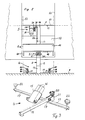
- the main assemblies of the inclined elevator are a main carrier 2, a roller carriage 3, a load suspension device 4, a motor drive 5, a support leg 6 and a support device 7 and a braking device 8.
- the main beam 2 is cut obliquely at its upper end, so that this inclined surface runs approximately horizontally when the main beam 2 is in use along a normal steep staircase for which the device is intended.
- the support device 7 consists of a rectangular plate which is rigidly attached to the obliquely cut off upper end 2a of the main carrier 2.
- the device can also be designed so that the inclination of the plate 7 relative to the main support 2 can be changed and the inclined position can be recorded.
- the lower end 2b of the main support 2 and the support foot 6 are connected to each other to absorb significant forces, but releasably.
- the main beam 2 is to be set up parallel or at an acute angle to the stairs 10 to be overcome with the support foot 6 on a floor surface 9, wherein the support device 7 is supported on the top step, near the edge 11 thereof.
- the length of the main girder 2 can be varied.
- the main beam 2 can consist of telescopic sections which can be locked against each other;
- the main carrier 2 it is preferred to form the main carrier 2 from sections 12, 13, 14 which can be plugged together.
- the sections 12 and 13 are of different lengths, and a device includes other plug elements of different lengths, not shown, so that a suitable overall length of the main support 2 is obtained by appropriate selection of the plug elements.
- the inclination of the stairs is indicated by the dash-dotted line 10a; the distance of the uppermost stair nosing 11 from the floor 9 over the line 10a is referred to as the stair length.
- the length of the main beam 2, including a pipe section 15 of the support leg 6, must at least reach the length of the stairs 10.
- the length of the main girder 2 will be somewhat longer than the length of the stairs, so that the axis of the main girder 2 is arranged at an acute angle with respect to the line of inclination 10a of the stairs.
- Fig. 3 the support leg 6 is shown in perspective.
- two U-profiles 16 are inserted in order to be able to insert the respective sections 12, 13 or 14 of the main support 2. It is understood that the set of sections 12, 13 is also provided with such U-profiles in order to be able to produce a corresponding rigid connection.
- the lower end of section 15 is chamfered to adapt to the floor 9.
- a tubular rod 17 is welded, which serves as a support for a pivotable boom 18, which is via an axis 19 and an adjusting screw 20 on a pocket-shaped Bearing bracket 21 is held.
- the set screw 20 can be supported on the bottom of the bearing housing 21 if the main carrier 2 threatens to tip forward due to the load from a wheelchair 1. Additional adjusting screws 22 at the ends of the rod 17 are also used for leveling. Instead of a single boom 18, as shown in FIG. 3, two booms can also be provided (FIG. 2).
- the main carrier 2 is designed such that it has an upper-side guide or track 2c and a lower-side guide or track 2d, which extend over the plug-in elements 12, 13, 14, 15. These plug-in elements are therefore preferably made from square tube. Of course, other profile rail pieces can also be used, which have an upper and lower-sided track.
- the frame 30 contains two band irons 30a, 30b (FIG. 4) which are held at a certain distance from one another via a bracket 31 and a web 32, so that the main support 2 with its lateral flanks 2e, 2f on the inside of these band irons 30a, 30b is present.
- the band irons 30a, 30b are bridged by a fixed axis 33 and approximately in the middle region by a displaceable axis 34 which is guided near their ends in slots 30c of the band irons 30a, 30b.
- the ends of the axes 34 are fastened in a carriage 36 which is guided on the outside of the band irons 30a, 30b and can be driven via an adjusting screw 37 which is supported on the web 32.
- the distance between the axes 33 and 34 can be adjusted by turning the adjusting screw 37.
- Rollers 38, 39 are rotatably mounted on the axes 33, 34 and are intended for rolling on the tracks 2c, 2d of the main carrier 2.
- the platform 40 has laterally attached plug-in holding means in the form of rectangular tubes 41, so that rod-shaped extensions of another platform 42 are inserted into the rectangular tubes 41 and the platforms 40 and 42 can be coupled to one another in this way.
- the platform 42 has a foot 43 and a pivotable ramp 44, which is useful for charging a wheelchair 1 when the platforms 40, 42 are moved near the ground, as indicated in Fig. 1 at 42 ', 44' in dash-dotted lines.
- the load-bearing means 4 is cantilevered on the roller trolley 3, so that on this a left-turning torque is exerted in Fig. 1, which by contacting the rollers 38, 39 on the top and bottom 2c, 2d the main carrier 2 is caught.
- the position of the frame plane 30 depends on the distance between the two rollers 38, 39 from one another - the closer the rollers are to one another, the higher the end of the frame connected to the roller 39 rises - so that the distance between the rollers 38 can be adjusted , 39 can determine the inclination of the frame 30 from one another.
- By moving the axis 34 by means of the adjusting screw 37 it can be achieved that the platforms 40, 42 are approximately horizontal.
- the braking device 8 attached to the chassis 3 is to take effect automatically when the drive 5 is de-energized becomes.
- an electromagnetically actuated brake can be arranged on one of the rollers 38, 39.
- a cup-shaped brake band as a braking device along the underside of the roller 38, one end 8a of which is attached to the bracket 31 and the end 29a of the cable 29, while the other, free end 8b extends into the gusset-shaped gap between the roller 38 and the underside 2d of the main carrier 2. If the cable 29 is somewhat slack and the roller 38 rotates clockwise in FIG.
- the end 8b of the brake band 8 can be pulled a little further into the gap, so that the clamping band 8 is pulled tightly onto the underside of the roller 38 is and acts on the braking downward movement of the roller trolley 3.
- the end 8b is pulled so far into the gap that self-locking occurs and the journey is interrupted.
- the inclined elevator finds space in a narrow space, as can be found when entering a bus.
- boundary lines 51, 52, 53 the door opening of this bus is touched only minimally by the inclined elevator, and the full clear dimension of this door opening remains unabated.
- Door openings are usually the critical point when using inclined lifts.
- the bracket 31 of the roller undercarriage can be pulled up to the deflection roller 28, which is equivalent to the fact that the load suspension device 4 is aligned in its uppermost position with the support device 7, as by dash-dotted lines at 4 'Indicated in Fig. 1.
- Platforms 40, 42 can therefore be unhindered in a wheelchair leave and reach the top staircase 11 or the vertical landing via the plate 7, which is to be overcome.
- load suspension device 4 has been described as a platform for receiving the wheelchair 1, the load suspension device can also be designed as a seat, transport container and the like.
- main carrier 2 has been described as being made of elements which can be plugged together, it is also possible to construct the main carrier from profile-like shapes arranged in several parts next to one another. For special cases, curved sections of the main girder can also be provided.
- parts 6, 12, 13 can be easily removed from part 14 and part 42 from part 40; the rest of the device then remains, as shown in FIG. 4.
- the handles 45 and 46 are provided for easier handling of this fuselage device.
- the inclined elevator described has the particular advantage that it can be made portable and can be set up on short stairs of approximately 1.5 m or on vertical heels without the use of tools or special fasteners.
- the inclined lift is easy to disassemble, and the individual parts can be stored in a small transport container and taken with you on trips.
Landscapes
- Engineering & Computer Science (AREA)
- Mechanical Engineering (AREA)
- Transportation (AREA)
- Automation & Control Theory (AREA)
- Structural Engineering (AREA)
- Health & Medical Sciences (AREA)
- Public Health (AREA)
- Life Sciences & Earth Sciences (AREA)
- Animal Behavior & Ethology (AREA)
- General Health & Medical Sciences (AREA)
- Veterinary Medicine (AREA)
- Types And Forms Of Lifts (AREA)
- Handcart (AREA)
Priority Applications (2)
| Application Number | Priority Date | Filing Date | Title |
|---|---|---|---|
| DE8888108226T DE3874327D1 (de) | 1988-05-24 | 1988-05-24 | Schraegaufzug. |
| EP19880108226 EP0343264B1 (fr) | 1988-05-24 | 1988-05-24 | Ascenseur incliné |
Applications Claiming Priority (1)
| Application Number | Priority Date | Filing Date | Title |
|---|---|---|---|
| EP19880108226 EP0343264B1 (fr) | 1988-05-24 | 1988-05-24 | Ascenseur incliné |
Publications (2)
| Publication Number | Publication Date |
|---|---|
| EP0343264A1 true EP0343264A1 (fr) | 1989-11-29 |
| EP0343264B1 EP0343264B1 (fr) | 1992-09-02 |
Family
ID=8198996
Family Applications (1)
| Application Number | Title | Priority Date | Filing Date |
|---|---|---|---|
| EP19880108226 Expired - Lifetime EP0343264B1 (fr) | 1988-05-24 | 1988-05-24 | Ascenseur incliné |
Country Status (2)
| Country | Link |
|---|---|
| EP (1) | EP0343264B1 (fr) |
| DE (1) | DE3874327D1 (fr) |
Cited By (7)
| Publication number | Priority date | Publication date | Assignee | Title |
|---|---|---|---|---|
| GB2231028B (en) * | 1989-05-05 | 1993-04-14 | Grorud Bison Bede Ltd | Stairlift |
| FR2726816A1 (fr) * | 1994-11-15 | 1996-05-15 | Dumont Jean Pierre | Dispositif de transport de charges sur un escalier droit |
| ES2155791A1 (es) * | 1999-07-05 | 2001-05-16 | Irizar S Coop | Elevador de minusvalidos para vehiculos. |
| WO2001053188A1 (fr) * | 2000-01-20 | 2001-07-26 | Stannah Stairlifts Limited | Mécanisme servant à régler les rouleaux du chariot d'un monte-escalier |
| WO2002005617A1 (fr) * | 2000-07-13 | 2002-01-24 | Stannah Stairlifts Limited | Ameliorations apportees aux monte-escaliers |
| DE102011109900B3 (de) * | 2011-08-10 | 2013-01-31 | Horst Rathert | Schrägaufzug insbesondere für Rollstühle mit faltbarer Plattform |
| ITUB20153415A1 (it) * | 2015-09-04 | 2017-03-04 | Contech Srl | "sistema di salita o discesa" |
Citations (4)
| Publication number | Priority date | Publication date | Assignee | Title |
|---|---|---|---|---|
| BE557425A (fr) * | ||||
| US2719607A (en) * | 1952-11-17 | 1955-10-04 | George P Scott | Stair elevator for invalids |
| EP0094607A2 (fr) * | 1982-05-17 | 1983-11-23 | César Rigert | Elévateur incliné pour un fauteuil roulant ou similaire monté sur un véhicule |
| CA1168183A (fr) * | 1983-05-04 | 1984-05-29 | John C. Kingston | Mecanisme d'embarquement et de debarquement pour handicapes transportes par vehicule routier |
-
1988
- 1988-05-24 EP EP19880108226 patent/EP0343264B1/fr not_active Expired - Lifetime
- 1988-05-24 DE DE8888108226T patent/DE3874327D1/de not_active Expired - Fee Related
Patent Citations (4)
| Publication number | Priority date | Publication date | Assignee | Title |
|---|---|---|---|---|
| BE557425A (fr) * | ||||
| US2719607A (en) * | 1952-11-17 | 1955-10-04 | George P Scott | Stair elevator for invalids |
| EP0094607A2 (fr) * | 1982-05-17 | 1983-11-23 | César Rigert | Elévateur incliné pour un fauteuil roulant ou similaire monté sur un véhicule |
| CA1168183A (fr) * | 1983-05-04 | 1984-05-29 | John C. Kingston | Mecanisme d'embarquement et de debarquement pour handicapes transportes par vehicule routier |
Cited By (10)
| Publication number | Priority date | Publication date | Assignee | Title |
|---|---|---|---|---|
| GB2231028B (en) * | 1989-05-05 | 1993-04-14 | Grorud Bison Bede Ltd | Stairlift |
| FR2726816A1 (fr) * | 1994-11-15 | 1996-05-15 | Dumont Jean Pierre | Dispositif de transport de charges sur un escalier droit |
| ES2155791A1 (es) * | 1999-07-05 | 2001-05-16 | Irizar S Coop | Elevador de minusvalidos para vehiculos. |
| WO2001053188A1 (fr) * | 2000-01-20 | 2001-07-26 | Stannah Stairlifts Limited | Mécanisme servant à régler les rouleaux du chariot d'un monte-escalier |
| US6755136B2 (en) | 2000-01-20 | 2004-06-29 | Stannah Stairlifts Limited | Carriage roller adjusting mechanism for stairlifts |
| WO2002005617A1 (fr) * | 2000-07-13 | 2002-01-24 | Stannah Stairlifts Limited | Ameliorations apportees aux monte-escaliers |
| GB2379209A (en) * | 2000-07-13 | 2003-03-05 | Stannah Stairlifts Ltd | Stairlift with variable force friction drive |
| GB2379209B (en) * | 2000-07-13 | 2004-06-23 | Stannah Stairlifts Ltd | Stairlift with variable force friction drive |
| DE102011109900B3 (de) * | 2011-08-10 | 2013-01-31 | Horst Rathert | Schrägaufzug insbesondere für Rollstühle mit faltbarer Plattform |
| ITUB20153415A1 (it) * | 2015-09-04 | 2017-03-04 | Contech Srl | "sistema di salita o discesa" |
Also Published As
| Publication number | Publication date |
|---|---|
| DE3874327D1 (de) | 1992-10-08 |
| EP0343264B1 (fr) | 1992-09-02 |
Similar Documents
| Publication | Publication Date | Title |
|---|---|---|
| DE69434331T2 (de) | Baustellen plattform | |
| DE2657605C2 (fr) | ||
| CH663934A5 (de) | Fahrzeug zum transport von personen und guetern auf treppen. | |
| DE3416222A1 (de) | Treppensteigende rollstuhl-transporteinrichtung | |
| DE3001298A1 (de) | Foerdersystem fuer einen treppenlift | |
| DE1255902B (de) | Verfahren zur Errichtung von Gebaeuden aus vorgefertigten Raumkaesten | |
| DE1194715B (de) | Vorrichtung zum Auf- und Abladen grosser, wagenkastenartiger Behaelter auf Fahrzeuge | |
| EP0343264B1 (fr) | Ascenseur incliné | |
| DE3103162C2 (fr) | ||
| DE3316034C2 (de) | Treppenlift, insbesondere zur Beförderung gehbehinderter Personen im Rollstuhl oder dergleichen | |
| DE4307450C1 (de) | Mechanische Parkeinrichtung | |
| DE2701981A1 (de) | Treppenfahrstuhl | |
| DE3446310A1 (de) | Regalfoerdersystem | |
| EP0217467A1 (fr) | Escalier | |
| DE3213774A1 (de) | Treppenaufzug, insbesondere fuer einen krankenfahrstuhl | |
| DE2914350C2 (de) | Aufzugseinrichtung | |
| DE3425998A1 (de) | Schraegaufzug | |
| DE3503836A1 (de) | Teleskoptreppe | |
| DE69410596T2 (de) | Vorrichtung zum hochsteigen | |
| DE2306358C3 (de) | Fahrzeug, insbesondere Lkw, für den Transport von Stahlbetonraumzellen, insbesondere Fertiggaragen | |
| DE19522939C2 (de) | Treppengängiges Fahrzeug | |
| DE3541176A1 (de) | Treppengleitender handkarren | |
| DE68904091T2 (de) | Leiterfahrkorb. | |
| DE8028658U1 (de) | Transportanhänger für unfallbeschädigte Fahrzeuge | |
| DE17182C (de) | Maschinenleiter für Feuerlösch-und Rettungswesen |
Legal Events
| Date | Code | Title | Description |
|---|---|---|---|
| PUAI | Public reference made under article 153(3) epc to a published international application that has entered the european phase |
Free format text: ORIGINAL CODE: 0009012 |
|
| AK | Designated contracting states |
Kind code of ref document: A1 Designated state(s): BE CH DE FR GB IT LI NL |
|
| 17P | Request for examination filed |
Effective date: 19900521 |
|
| 17Q | First examination report despatched |
Effective date: 19910502 |
|
| ITF | It: translation for a ep patent filed | ||
| GRAA | (expected) grant |
Free format text: ORIGINAL CODE: 0009210 |
|
| AK | Designated contracting states |
Kind code of ref document: B1 Designated state(s): BE CH DE FR GB IT LI NL |
|
| REF | Corresponds to: |
Ref document number: 3874327 Country of ref document: DE Date of ref document: 19921008 |
|
| GBT | Gb: translation of ep patent filed (gb section 77(6)(a)/1977) | ||
| ET | Fr: translation filed | ||
| PLBE | No opposition filed within time limit |
Free format text: ORIGINAL CODE: 0009261 |
|
| STAA | Information on the status of an ep patent application or granted ep patent |
Free format text: STATUS: NO OPPOSITION FILED WITHIN TIME LIMIT |
|
| 26N | No opposition filed | ||
| PGFP | Annual fee paid to national office [announced via postgrant information from national office to epo] |
Ref country code: GB Payment date: 19960530 Year of fee payment: 9 Ref country code: FR Payment date: 19960530 Year of fee payment: 9 |
|
| PGFP | Annual fee paid to national office [announced via postgrant information from national office to epo] |
Ref country code: NL Payment date: 19960531 Year of fee payment: 9 |
|
| PGFP | Annual fee paid to national office [announced via postgrant information from national office to epo] |
Ref country code: CH Payment date: 19960612 Year of fee payment: 9 |
|
| PGFP | Annual fee paid to national office [announced via postgrant information from national office to epo] |
Ref country code: BE Payment date: 19960625 Year of fee payment: 9 |
|
| PG25 | Lapsed in a contracting state [announced via postgrant information from national office to epo] |
Ref country code: GB Effective date: 19970524 |
|
| PG25 | Lapsed in a contracting state [announced via postgrant information from national office to epo] |
Ref country code: LI Free format text: LAPSE BECAUSE OF NON-PAYMENT OF DUE FEES Effective date: 19970531 Ref country code: CH Free format text: LAPSE BECAUSE OF NON-PAYMENT OF DUE FEES Effective date: 19970531 Ref country code: BE Effective date: 19970531 |
|
| BERE | Be: lapsed |
Owner name: PETER AUER A.G. Effective date: 19970531 |
|
| PG25 | Lapsed in a contracting state [announced via postgrant information from national office to epo] |
Ref country code: NL Effective date: 19971201 |
|
| GBPC | Gb: european patent ceased through non-payment of renewal fee |
Effective date: 19970524 |
|
| REG | Reference to a national code |
Ref country code: CH Ref legal event code: PL |
|
| PG25 | Lapsed in a contracting state [announced via postgrant information from national office to epo] |
Ref country code: FR Free format text: LAPSE BECAUSE OF NON-PAYMENT OF DUE FEES Effective date: 19980130 |
|
| NLV4 | Nl: lapsed or anulled due to non-payment of the annual fee |
Effective date: 19971201 |
|
| REG | Reference to a national code |
Ref country code: FR Ref legal event code: ST |
|
| PGFP | Annual fee paid to national office [announced via postgrant information from national office to epo] |
Ref country code: DE Payment date: 20000605 Year of fee payment: 13 |
|
| PG25 | Lapsed in a contracting state [announced via postgrant information from national office to epo] |
Ref country code: DE Free format text: LAPSE BECAUSE OF NON-PAYMENT OF DUE FEES Effective date: 20020301 |
|
| PG25 | Lapsed in a contracting state [announced via postgrant information from national office to epo] |
Ref country code: IT Free format text: LAPSE BECAUSE OF NON-PAYMENT OF DUE FEES;WARNING: LAPSES OF ITALIAN PATENTS WITH EFFECTIVE DATE BEFORE 2007 MAY HAVE OCCURRED AT ANY TIME BEFORE 2007. THE CORRECT EFFECTIVE DATE MAY BE DIFFERENT FROM THE ONE RECORDED. Effective date: 20050524 |