EP0343340A1 - Verfahren und Vorrichtung zur Reinigung eines Drahtseiles - Google Patents
Verfahren und Vorrichtung zur Reinigung eines Drahtseiles Download PDFInfo
- Publication number
- EP0343340A1 EP0343340A1 EP89105136A EP89105136A EP0343340A1 EP 0343340 A1 EP0343340 A1 EP 0343340A1 EP 89105136 A EP89105136 A EP 89105136A EP 89105136 A EP89105136 A EP 89105136A EP 0343340 A1 EP0343340 A1 EP 0343340A1
- Authority
- EP
- European Patent Office
- Prior art keywords
- wire rope
- tools
- path
- strands
- slats
- Prior art date
- Legal status (The legal status is an assumption and is not a legal conclusion. Google has not performed a legal analysis and makes no representation as to the accuracy of the status listed.)
- Granted
Links
Images


Classifications
-
- B—PERFORMING OPERATIONS; TRANSPORTING
- B08—CLEANING
- B08B—CLEANING IN GENERAL; PREVENTION OF FOULING IN GENERAL
- B08B1/00—Cleaning by methods involving the use of tools
- B08B1/20—Cleaning of moving articles, e.g. of moving webs or of objects on a conveyor
-
- B—PERFORMING OPERATIONS; TRANSPORTING
- B08—CLEANING
- B08B—CLEANING IN GENERAL; PREVENTION OF FOULING IN GENERAL
- B08B1/00—Cleaning by methods involving the use of tools
- B08B1/30—Cleaning by methods involving the use of tools by movement of cleaning members over a surface
- B08B1/32—Cleaning by methods involving the use of tools by movement of cleaning members over a surface using rotary cleaning members
-
- B—PERFORMING OPERATIONS; TRANSPORTING
- B61—RAILWAYS
- B61B—RAILWAY SYSTEMS; EQUIPMENT THEREFOR NOT OTHERWISE PROVIDED FOR
- B61B12/00—Component parts, details or accessories not provided for in groups B61B7/00 - B61B11/00
- B61B12/08—Cable lubrication
-
- F—MECHANICAL ENGINEERING; LIGHTING; HEATING; WEAPONS; BLASTING
- F16—ENGINEERING ELEMENTS AND UNITS; GENERAL MEASURES FOR PRODUCING AND MAINTAINING EFFECTIVE FUNCTIONING OF MACHINES OR INSTALLATIONS; THERMAL INSULATION IN GENERAL
- F16N—LUBRICATING
- F16N7/00—Arrangements for supplying oil or unspecified lubricant from a stationary reservoir or the equivalent in or on the machine or member to be lubricated
-
- Y—GENERAL TAGGING OF NEW TECHNOLOGICAL DEVELOPMENTS; GENERAL TAGGING OF CROSS-SECTIONAL TECHNOLOGIES SPANNING OVER SEVERAL SECTIONS OF THE IPC; TECHNICAL SUBJECTS COVERED BY FORMER USPC CROSS-REFERENCE ART COLLECTIONS [XRACs] AND DIGESTS
- Y10—TECHNICAL SUBJECTS COVERED BY FORMER USPC
- Y10S—TECHNICAL SUBJECTS COVERED BY FORMER USPC CROSS-REFERENCE ART COLLECTIONS [XRACs] AND DIGESTS
- Y10S118/00—Coating apparatus
- Y10S118/21—Wire and cord striper
Definitions
- the present invention deals generally with a method and apparatus for contact treating the surface of wire rope and more specifically is directed to an improved method and apparatus for cleaning wire rope while the rope is operational as a part within a system or machine.
- Wire rope is frequently employed as a means to transmit power and or motion within a system such as a ski-lift or elevator or within a machine such as a power shovel, and the like. Often the wire rope in such a system or machine collects dirt or debris on its outer surface as it is operational, that is during the periods that the wire rope is moved therein, and this way be further aggravated because such dirt and debris is attracted to and held by lubricant that is normally required to be present on the wire rope.
- Another object of the present invention is to provide an improved method and apparatus for cleaning the surface of wire rope while the wire rope is in operation as a part of a system or machine.
- the present invention involves spinning a plurality of treatment tools around a wire rope, while maintaining the tools in contact with the rope surface, at a fixed location along the path of the wire rope while it is operational and moving in a system or machine.
- An apparatus devised to perform the method comprises a cage means mountable upon a wire rope with a plurality of tools extending inwardly from the cage, a follower means fixed to the cage and tracking the surface strands of wire rope to cause the cage to spin with the strands, and a yoke means rotatably connected to the cage means to anchor the cage at a fixed location along the path of the wire rope.
- the present method it is intended to arrange a plurality of tools about a wire rope at a zone fixed along the wire rope path, such as in a ski lift system or the like, and as the wire rope is drawn through the zone to cause the tools to spin around the wire rope, preferably in synchronism with the lay or twist rate of the outer strands making up the outer surface of the wire rope.
- the tools will be caused to track with the wire rope outer strands and may be extended into continuous contact with valleys between strands as well as the outermost surfaces of the wire rope strands.
- Spinning of the tools is accomplished by arranging the tools radially about the wire rope path and connecting them to one or more followers which are caused to ride in the valleys between strands. At the same time the followers, and tools, are held to a fixed axial location along the path of the wire rope, and prevented from being moved axially therewith, whereby the followers and tools will be rotated and move circularly around the wire rope as the rope is moved axially past or through the fixed position.
- a cage means which encompasses the wire rope path, thereby defining a zone around a wire rope, and which cage means is rotatably connected to a yoke means by which it may be anchored at a desired location along the wire rope path.
- the tools may alternatively comprise brushing, scraping and surface applying (such as lubricating) elements in the form of brushes, scrapers and wipers; and it is possible to utilize such elements separately or in combination as may be required by the condition of the wire rope.
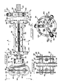
- FIGURES 1-8 A preferred apparatus embodiment is illustrated in FIGURES 1-8 wherein a cage generally 20 is comprised of a plurality of longitudinal slats 22 connected between forward and rearward encirclements generally 24,26, and is rotatably connected at the forward encirclement to a yoke generally 30 by a hollow bearing generally 34.
- the yoke 30 comprises a pair of aligned sheaves 36, 38 rotatably mounted on shafts 40, 42 extending between a pair of plates 44, 46 so as to form a pinch area aligned with the axis of the cage 20.
- follower ring At the opposite end of the cage generally 20 connected rearwardly of the rearward encirclement generally 26 is follower ring generally 56 which holds a plurality of followers generally 60 extending radially inwardly toward the axis of the cage 20.
- a plurality of tools generally 70 are adjustably secured to the cage slats 22 and extending radially inwardly toward the cage axis (and wire rope - extending axially through the cage 20).
- each plate 44, 46 of the yoke 30 includes an eye bolt 84 by which the yoke may be anchored in place by chains or the like (not shown) so as to not move with the wire rope.
- the hollow bearing generally 34 connecting yoke 30 to cage 20 is comprised of two symmetrical semi-cylinders 90, 92 having an exterior race way 94, which is received in the bearing block 52 fastened to yoke 30, and bifurcated flanges 96, 98 which are fastened, by bolts or the like, to the forward encirclement 24.
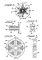
- the forward encirclement generally 24 is shown in detail in FIGURES 7 and 8 and is also seen in FIGURE 4. It is comprised of two semicircular plates 104, 106 which are pivotally connected at one side by a hinge piece 108 and secured by a removable pin 110 at an opposite side. Each semicircular plate contains a plurality of pockets 112 each having outwardly extending holes 114 for adjustment bolts 116 which are fastened against the forward ends of respective slats 22.
- the slats 22 extend between the forward encirclement 24 and the rearward encirclement 26, which is similarly constructed of two semicircular plates 124, 126 that are hinged together and which contain slat pockets and adjustment bolts 130.
- the tools generally 70 shown in FIGURES 1 and 4 are metal brushes 134 mounted on wooden backings 136 which are secured by screws 138 at an angle to the slats 22 which angle is preferably set to match the lay or angle of the strands on the wire rope 64 being cleaned.
- the follower ring 56 of the preferred embodiment is made up of two arcuate ring sections 144 and 146 which are pivotally connected by a hinge 150 at one side and secured by a pin 152 at the opposite side. It is to be noted that the hinges of each of the forward and rearward encirclements 24, 26 and the follower ring 56 are aligned at the same side of the cage generally 20, so that the entire cage is divided into two halves which may be opened.
- each ring section 144, 146 is spaced from but rigidly attached to a corresponding semicircular plate 124, 126 (of the rearward encirclement 26) by two support bars 154.
- the followers generally 60 mounted to the follower ring generally 56 will be seen to each comprise a narrow profile roller 160 (having a V shaped cross section) held radially inward of a ring section 144 or 146 by a pin 162 in a bifurcated holder 164, which holder is pivotably and reciprocally mounted against a compression spring 166 on a shaft 168.
- each shaft 168 extends outwardly through a sleeve 170 mounted in a ring section 144, 146, and male threads 172 on the shaft 168 are engaged by internal threads of a cap 174 which is fitted within the sleeve 170.
- each roller 160 is adjustable radially and will be resiliently held against a wire rope 64 extending through the cage 20.
- the shaft 168 - holder 164 interconnection permits the roller 160 to freely twist and thereby become seated in a valley between two adjacent wire rope strands.
- the follower rollers 160 will track the wire rope strands and impart a rotary or spinning motion to the follower ring 56 and thereby to the entire cage generally 20.
- the tools 70 such as brushes 134, mounted to the slats 22 of the cage 20 will also follow the outer surface strands of the wire rope 64 to thereby effectively contact all of the surface area thereof.
- FIGURES 9 and 10 A second simplified apparatus embodiment is shown in FIGURES 9 and 10.
- a cage generally 20′ is comprised of a plurality of slats 22′ extending between two hinged end collars 200, 202 having open centers.
- Each slat 22′ is simply directly fastened, by screws or the like, at each end to an inwardly extending lip 204 of each collar.
- the collar 202 holds an annular split bearing (not shown) and a rotatable face plate 210 fits outwardly of the collar 202 with an internal hollow hub (also not shown) held within the annular split bearing.
- the face plate 210 and hub are similarly split so as to facilitate placement about a wire rope.
- a yoke 30′ comprising a simple cross bar 214 with eyelets 216 at each end is secured to the face plate.
- the opposite collar 200 surrounds a hollow split hub 220 which centers the cage 20′ on a longitudinally extending wire rope.
- Followers generally 60′ are mounted directly to the centers of slats 22′ and may take the form of threaded bolts 224 having pointed stylus ends 226 which function to both track the wire rope strands and clean debris from the strand valleys.
- the tools 70′ are also directly mounted to the slats and may take the form of brushes 228 extending from the ends of adjustable bolts 230. Both sets of bolts 224 and 230 may be secured so as to be adjustable radially of the cage 20′ by lock nuts 232.
- one set of tools 70′ which encircle the wire rope path is also made longitudinally adjustable by providing slots 236 in each slat 22′.
- FIGURES 12 and 13 alternate forms of tools are shown. Instead of brushes the tools in either embodiment may take the form of scrapers 250 or 252 which are shaped to the contour of one or two adjacent strands. It is also possible to provide other contours as may be found to be advantageous.
- FIGURE 11 a form of tool illustrated for applying an agent to a wire rope surface.
- a rotary fluid coupling generally 260 is mounted on an encirclement generally 24 or 26 of the preferred embodiment (or a collar 200 or 202 of the second embodiment) and a plurality of wiper tools 262 are mounted to the slats 22 of a cage generally 20.
- Fluid conduits 264 are connected between the wiper 262 and the inner rotary portion of coupling 260 and another conduit 266 is connected between a stationary outer portion of the coupling 260 and a source of appropriate fluid (not shown) such as a lubricant.
Landscapes
- Engineering & Computer Science (AREA)
- General Engineering & Computer Science (AREA)
- Mechanical Engineering (AREA)
- Transportation (AREA)
- Cleaning In General (AREA)
- Ropes Or Cables (AREA)
- Cleaning And De-Greasing Of Metallic Materials By Chemical Methods (AREA)
Priority Applications (1)
| Application Number | Priority Date | Filing Date | Title |
|---|---|---|---|
| AT89105136T ATE90288T1 (de) | 1988-05-23 | 1989-03-22 | Verfahren und vorrichtung zur reinigung eines drahtseiles. |
Applications Claiming Priority (2)
| Application Number | Priority Date | Filing Date | Title |
|---|---|---|---|
| US07/197,519 US4982473A (en) | 1988-05-23 | 1988-05-23 | Wire rope cleaning apparatus |
| US197519 | 1988-05-23 |
Publications (2)
| Publication Number | Publication Date |
|---|---|
| EP0343340A1 true EP0343340A1 (de) | 1989-11-29 |
| EP0343340B1 EP0343340B1 (de) | 1993-06-09 |
Family
ID=22729739
Family Applications (1)
| Application Number | Title | Priority Date | Filing Date |
|---|---|---|---|
| EP89105136A Expired - Lifetime EP0343340B1 (de) | 1988-05-23 | 1989-03-22 | Verfahren und Vorrichtung zur Reinigung eines Drahtseiles |
Country Status (8)
| Country | Link |
|---|---|
| US (1) | US4982473A (de) |
| EP (1) | EP0343340B1 (de) |
| AT (1) | ATE90288T1 (de) |
| CA (1) | CA1329353C (de) |
| DE (1) | DE68906962T2 (de) |
| MX (1) | MX164324B (de) |
| ZA (1) | ZA892344B (de) |
| ZW (1) | ZW4289A1 (de) |
Cited By (7)
| Publication number | Priority date | Publication date | Assignee | Title |
|---|---|---|---|---|
| AT398241B (de) * | 1992-10-22 | 1994-10-25 | Austria Draht Gmbh | Verfahren und vorrichtung zur schmierung von drahtseilen |
| ES2130910A1 (es) * | 1996-02-14 | 1999-07-01 | Auxiliar Minera Del Norte S A | Aparato limpiador y de mantenimiento de cables. |
| WO2004000473A1 (de) * | 2002-06-21 | 2003-12-31 | Neumeyer Erwin S | Gerät und verfahren zum behandeln eines seils |
| CN102773222A (zh) * | 2012-08-03 | 2012-11-14 | 山东送变电工程公司 | 钢丝绳旋转除污装置 |
| WO2015022068A3 (en) * | 2013-08-15 | 2015-07-30 | Muehlhan Ag | Apparatus for surface treatment of an elongate object |
| CN107597635A (zh) * | 2017-09-15 | 2018-01-19 | 西北工业大学 | 一种线缆清洗装置 |
| US20220170590A1 (en) * | 2019-02-27 | 2022-06-02 | Furrer + Frey Ag | Greasing sleeve |
Families Citing this family (17)
| Publication number | Priority date | Publication date | Assignee | Title |
|---|---|---|---|---|
| US6990707B1 (en) | 1996-06-03 | 2006-01-31 | Heumann Steven A | Cylindrical member maintenance device |
| US7310111B2 (en) * | 1999-08-12 | 2007-12-18 | Innovation Institute | Video monitoring and security system |
| US20040216254A1 (en) * | 2003-05-02 | 2004-11-04 | Trojan Technologies Inc. | Sectoral ring brush |
| US20060174434A1 (en) * | 2003-06-11 | 2006-08-10 | Heumann Steven A | Cylindrical member maintenance device |
| CN101713397B (zh) * | 2003-12-30 | 2014-07-09 | 艾默生环境优化技术有限公司 | 压缩机保护和诊断系统 |
| USD528891S1 (en) | 2005-05-09 | 2006-09-26 | Thompson Stephen J | Hand tool for abrading oxides from copper electrical wires |
| US20080023123A1 (en) * | 2006-07-31 | 2008-01-31 | Schlumberger Technology Corporation | Automatic elastomer extrusion apparatus and method |
| US20090044369A1 (en) * | 2007-08-16 | 2009-02-19 | Heumann Steven A | Cylindrical member maintenance device including cutting ring |
| FR2961118B1 (fr) * | 2010-06-11 | 2013-03-01 | Michelin Soc Tech | Dispositif et procede de nettoyage d'un fil |
| KR101420985B1 (ko) * | 2010-09-23 | 2014-07-17 | 미쓰비시 덴키 빌딩 테크노 서비스 가부시키 가이샤 | 와이어 로프 청소 기구 |
| US10286428B2 (en) * | 2011-10-19 | 2019-05-14 | Pgs Geophysical As | Tools and methods for cleaning survey cables |
| US10744546B2 (en) * | 2016-04-01 | 2020-08-18 | Automated Industrial Machinery, Inc. | Wire cleaning apparatus and method |
| FR3057524B1 (fr) * | 2016-10-17 | 2018-11-23 | Poma | Dispositif et procede de repositionnement du cable porteur d'une installation de transport par cable. |
| US10730721B2 (en) | 2018-03-02 | 2020-08-04 | Otis Elevator Company | Rope cleaning device |
| CN114273285B (zh) * | 2021-12-27 | 2022-11-01 | 鹰潭市钲旺科技有限公司 | 一种循环多级净化的铜包铜线表面清洗装置 |
| CN114940426B (zh) * | 2022-05-12 | 2024-02-02 | 洛阳威卡矿山机械设备有限公司 | 一种矿用提升钢丝绳自动涂油装置 |
| CN118908087B (zh) * | 2024-08-12 | 2025-04-18 | 浙江省特种设备科学研究院 | 船用起重机收钩清洁装置 |
Citations (3)
| Publication number | Priority date | Publication date | Assignee | Title |
|---|---|---|---|---|
| CH301630A (de) * | 1952-12-02 | 1954-09-15 | Frey Benedikt | Drahtseilreinigungsapparat. |
| CH316318A (de) * | 1955-09-24 | 1956-09-30 | Hartmann Walter | Drahtseilreinigungsapparat |
| US4570285A (en) * | 1982-12-10 | 1986-02-18 | Skelton Alan W | Wire rope cleaning devices |
Family Cites Families (1)
| Publication number | Priority date | Publication date | Assignee | Title |
|---|---|---|---|---|
| GB858832A (en) * | 1957-04-17 | 1961-01-18 | David Gladstone Balfour Reekie | Improvements in and relating to apparatus for cleaning wire ropes or cables |
-
1988
- 1988-05-23 US US07/197,519 patent/US4982473A/en not_active Expired - Fee Related
-
1989
- 1989-03-20 ZW ZW42/89A patent/ZW4289A1/xx unknown
- 1989-03-22 EP EP89105136A patent/EP0343340B1/de not_active Expired - Lifetime
- 1989-03-22 AT AT89105136T patent/ATE90288T1/de not_active IP Right Cessation
- 1989-03-22 DE DE8989105136T patent/DE68906962T2/de not_active Expired - Fee Related
- 1989-03-30 ZA ZA892344A patent/ZA892344B/xx unknown
- 1989-04-05 CA CA000595755A patent/CA1329353C/en not_active Expired - Fee Related
- 1989-05-12 MX MX16015A patent/MX164324B/es unknown
Patent Citations (3)
| Publication number | Priority date | Publication date | Assignee | Title |
|---|---|---|---|---|
| CH301630A (de) * | 1952-12-02 | 1954-09-15 | Frey Benedikt | Drahtseilreinigungsapparat. |
| CH316318A (de) * | 1955-09-24 | 1956-09-30 | Hartmann Walter | Drahtseilreinigungsapparat |
| US4570285A (en) * | 1982-12-10 | 1986-02-18 | Skelton Alan W | Wire rope cleaning devices |
Non-Patent Citations (4)
| Title |
|---|
| Soviet Inventions Illustrated, P,Q Section, Week 8430, September 05, 1987 Derwent Publications Ltd., London, Q 3, page 7 * SU-1054-263-A (Novokrama) * * |
| Soviet Inventions Illustrated, P,Q Section, Week 8933, September 30, 1987 Derwent Publications Ltd., London, Q 38, page 6 & SU-1281-495-A (Ryanovsk Lead Com) * * |
| Soviet Inventions Illustrated, P,Q Section, Week B 39, November 07, 1979 Derwent Publications Ltd., London, Q 3, page 5 * SU-639 793 (Petrov) * * |
| Soviet Inventions Illustrated, P,Q Section, Week E 13, May 12, 1982 Derwent Publications Ltd., London, Q 38, page 23 * SU-839 962 (Novo-Kramatorskii) * * |
Cited By (10)
| Publication number | Priority date | Publication date | Assignee | Title |
|---|---|---|---|---|
| AT398241B (de) * | 1992-10-22 | 1994-10-25 | Austria Draht Gmbh | Verfahren und vorrichtung zur schmierung von drahtseilen |
| ES2130910A1 (es) * | 1996-02-14 | 1999-07-01 | Auxiliar Minera Del Norte S A | Aparato limpiador y de mantenimiento de cables. |
| WO2004000473A1 (de) * | 2002-06-21 | 2003-12-31 | Neumeyer Erwin S | Gerät und verfahren zum behandeln eines seils |
| CN102773222A (zh) * | 2012-08-03 | 2012-11-14 | 山东送变电工程公司 | 钢丝绳旋转除污装置 |
| WO2015022068A3 (en) * | 2013-08-15 | 2015-07-30 | Muehlhan Ag | Apparatus for surface treatment of an elongate object |
| US9649667B2 (en) | 2013-08-15 | 2017-05-16 | Muehlhan Ag | Apparatus for surface treatment of an elongate object |
| CN107597635A (zh) * | 2017-09-15 | 2018-01-19 | 西北工业大学 | 一种线缆清洗装置 |
| US20220170590A1 (en) * | 2019-02-27 | 2022-06-02 | Furrer + Frey Ag | Greasing sleeve |
| US12043293B2 (en) * | 2019-02-27 | 2024-07-23 | Furrer + Frey Ag | Greasing sleeve |
| US12344283B2 (en) * | 2019-02-27 | 2025-07-01 | Furrer + Frey Ag | Greasing sleeve |
Also Published As
| Publication number | Publication date |
|---|---|
| EP0343340B1 (de) | 1993-06-09 |
| MX164324B (es) | 1992-08-03 |
| ZW4289A1 (en) | 1991-02-27 |
| ATE90288T1 (de) | 1993-06-15 |
| DE68906962D1 (de) | 1993-07-15 |
| US4982473A (en) | 1991-01-08 |
| ZA892344B (en) | 1989-11-29 |
| DE68906962T2 (de) | 1993-09-16 |
| CA1329353C (en) | 1994-05-10 |
Similar Documents
| Publication | Publication Date | Title |
|---|---|---|
| US4982473A (en) | Wire rope cleaning apparatus | |
| US4570285A (en) | Wire rope cleaning devices | |
| US4169427A (en) | Cable cleaning unit | |
| US3583555A (en) | Cleaning apparatus for conveyor belts or the like | |
| US3214824A (en) | Scaling device for cylindrical objects and the like | |
| SE416033B (sv) | Anordning for bearbetning av ytan pa foremal med oregelbundna konturer | |
| CN105605393A (zh) | 一种钢丝绳润滑装置 | |
| US7575509B2 (en) | Machine for scrubbing exterior of fowl and method of use thereof | |
| JPS63296945A (ja) | オフセット印刷機のゴム胴外套面用洗浄装置 | |
| US5001801A (en) | Oscillating line travel pipe cleaning machine | |
| US4142267A (en) | Brush frame and shell | |
| CA1185554A (en) | Slat conveyor | |
| DE19628275C2 (de) | Verringerung von Handlaufvibrationen bei Fahrgastbeförderern | |
| CN114940426B (zh) | 一种矿用提升钢丝绳自动涂油装置 | |
| CN214594082U (zh) | 一种滚筒输送清理机 | |
| NL8104127A (nl) | Metalen borstel en zijn toepassing bij het verwijderen van een anti-corrosie bekleding. | |
| WO1987007534A1 (en) | Service lubricating of metal haulage cables | |
| KR200183723Y1 (ko) | 링크체인의 청소 및 오일도포장치 | |
| JP2600732Y2 (ja) | ワイヤロープ用清掃装置および余剰潤滑材除去装置 | |
| GB2131465A (en) | Rope cleaner | |
| US4542555A (en) | Device for cleaning a collecting rope from oil or similar material | |
| DE3913268C1 (de) | ||
| US4793015A (en) | Apparatus for cleaning eggs and like articles | |
| SU1421659A1 (ru) | Устройство дл очистки каната | |
| JP3603233B2 (ja) | トロリー・コンベアー・レール内掃除具 |
Legal Events
| Date | Code | Title | Description |
|---|---|---|---|
| PUAI | Public reference made under article 153(3) epc to a published international application that has entered the european phase |
Free format text: ORIGINAL CODE: 0009012 |
|
| AK | Designated contracting states |
Kind code of ref document: A1 Designated state(s): AT BE CH DE ES FR GB IT LI LU NL SE |
|
| 17P | Request for examination filed |
Effective date: 19900125 |
|
| 17Q | First examination report despatched |
Effective date: 19910402 |
|
| GRAA | (expected) grant |
Free format text: ORIGINAL CODE: 0009210 |
|
| AK | Designated contracting states |
Kind code of ref document: B1 Designated state(s): AT BE CH DE ES FR GB IT LI LU NL SE |
|
| PG25 | Lapsed in a contracting state [announced via postgrant information from national office to epo] |
Ref country code: IT Free format text: LAPSE BECAUSE OF FAILURE TO SUBMIT A TRANSLATION OF THE DESCRIPTION OR TO PAY THE FEE WITHIN THE PRE;WARNING: LAPSES OF ITALIAN PATENTS WITH EFFECTIVE DATE BEFORE 2007 MAY HAVE OCCURRED AT ANY TIME BEFORE 2007. THE CORRECT EFFECTIVE DATE MAY BE DIFFERENT FROM THE ONE RECORDED.SCRIBED TIME-LIMIT Effective date: 19930609 Ref country code: ES Free format text: THE PATENT HAS BEEN ANNULLED BY A DECISION OF A NATIONAL AUTHORITY Effective date: 19930609 Ref country code: AT Effective date: 19930609 Ref country code: BE Effective date: 19930609 Ref country code: CH Effective date: 19930609 Ref country code: LI Effective date: 19930609 Ref country code: SE Effective date: 19930609 Ref country code: NL Effective date: 19930609 |
|
| REF | Corresponds to: |
Ref document number: 90288 Country of ref document: AT Date of ref document: 19930615 Kind code of ref document: T |
|
| REF | Corresponds to: |
Ref document number: 68906962 Country of ref document: DE Date of ref document: 19930715 |
|
| REG | Reference to a national code |
Ref country code: CH Ref legal event code: PL |
|
| ET | Fr: translation filed | ||
| NLV1 | Nl: lapsed or annulled due to failure to fulfill the requirements of art. 29p and 29m of the patents act | ||
| PG25 | Lapsed in a contracting state [announced via postgrant information from national office to epo] |
Ref country code: GB Effective date: 19940322 |
|
| PG25 | Lapsed in a contracting state [announced via postgrant information from national office to epo] |
Ref country code: LU Free format text: LAPSE BECAUSE OF NON-PAYMENT OF DUE FEES Effective date: 19940331 |
|
| PLBE | No opposition filed within time limit |
Free format text: ORIGINAL CODE: 0009261 |
|
| STAA | Information on the status of an ep patent application or granted ep patent |
Free format text: STATUS: NO OPPOSITION FILED WITHIN TIME LIMIT |
|
| 26N | No opposition filed | ||
| GBPC | Gb: european patent ceased through non-payment of renewal fee |
Effective date: 19940322 |
|
| PGFP | Annual fee paid to national office [announced via postgrant information from national office to epo] |
Ref country code: FR Payment date: 19950210 Year of fee payment: 7 |
|
| PGFP | Annual fee paid to national office [announced via postgrant information from national office to epo] |
Ref country code: DE Payment date: 19950227 Year of fee payment: 7 |
|
| PG25 | Lapsed in a contracting state [announced via postgrant information from national office to epo] |
Ref country code: FR Effective date: 19961129 |
|
| PG25 | Lapsed in a contracting state [announced via postgrant information from national office to epo] |
Ref country code: DE Effective date: 19961203 |
|
| REG | Reference to a national code |
Ref country code: FR Ref legal event code: ST |