EP0343481A2 - Dispositif et procédé pour contrôler des moteurs à courant continu sans balais tétraphasé - Google Patents
Dispositif et procédé pour contrôler des moteurs à courant continu sans balais tétraphasé Download PDFInfo
- Publication number
- EP0343481A2 EP0343481A2 EP19890108717 EP89108717A EP0343481A2 EP 0343481 A2 EP0343481 A2 EP 0343481A2 EP 19890108717 EP19890108717 EP 19890108717 EP 89108717 A EP89108717 A EP 89108717A EP 0343481 A2 EP0343481 A2 EP 0343481A2
- Authority
- EP
- European Patent Office
- Prior art keywords
- switches
- closed
- open
- switch
- control device
- Prior art date
- Legal status (The legal status is an assumption and is not a legal conclusion. Google has not performed a legal analysis and makes no representation as to the accuracy of the status listed.)
- Withdrawn
Links
- 238000000034 method Methods 0.000 title claims description 9
- 238000004804 winding Methods 0.000 claims abstract description 23
- 239000004065 semiconductor Substances 0.000 claims abstract description 16
- 238000010615 ring circuit Methods 0.000 claims description 5
- 239000000696 magnetic material Substances 0.000 claims description 3
- 206010034016 Paronychia Diseases 0.000 description 2
- 238000010586 diagram Methods 0.000 description 2
- 238000005476 soldering Methods 0.000 description 2
- 239000003990 capacitor Substances 0.000 description 1
- 230000000295 complement effect Effects 0.000 description 1
- 238000009499 grossing Methods 0.000 description 1
Images


Classifications
-
- H—ELECTRICITY
- H02—GENERATION; CONVERSION OR DISTRIBUTION OF ELECTRIC POWER
- H02K—DYNAMO-ELECTRIC MACHINES
- H02K29/00—Motors or generators having non-mechanical commutating devices, e.g. discharge tubes or semiconductor devices
- H02K29/06—Motors or generators having non-mechanical commutating devices, e.g. discharge tubes or semiconductor devices with position sensing devices
- H02K29/08—Motors or generators having non-mechanical commutating devices, e.g. discharge tubes or semiconductor devices with position sensing devices using magnetic effect devices, e.g. Hall-plates, magneto-resistors
-
- H—ELECTRICITY
- H02—GENERATION; CONVERSION OR DISTRIBUTION OF ELECTRIC POWER
- H02P—CONTROL OR REGULATION OF ELECTRIC MOTORS, ELECTRIC GENERATORS OR DYNAMO-ELECTRIC CONVERTERS; CONTROLLING TRANSFORMERS, REACTORS OR CHOKE COILS
- H02P6/00—Arrangements for controlling synchronous motors or other dynamo-electric motors using electronic commutation dependent on the rotor position; Electronic commutators therefor
- H02P6/14—Electronic commutators
Definitions
- the invention relates to a device and a method for controlling brushless, in particular 4-strand DC motors.
- the rotating fields required for converting electrical into mechanical energy by means of electric motors can be generated mechanically (brushes in connection with collectors attached to the rotor) or electronically using semiconductor switches.
- a brushless DC motor is known from US Pat. No. 4,484,115, the stator of which is wound with a 7-strand winding in star or ring connection.
- the rotor of the DC motor is covered with permanent magnets.
- the current required to generate a rotating field is controlled with the aid of semiconductor switches, for the control of which a position sensor which detects the rotor position is used. Two semiconductor switches are assigned to each winding phase to enable bipolar operation.
- the brushless direct current motor described in the US patent has the disadvantage that a pair of complementary transistors is required for its control per line. This is a complex and costly solution.
- the brushless DC motor according to DE-PS 33 01 801 has the disadvantage that the stator winding strands are connected in a star connection. With this switching of the stator winding, the stator cannot be wound fully automatically, and soldering work is also required on the winding heads. In addition, with such a stator winding, the end windings become quite large in the axial direction, which leads to additional electrical losses.
- the object of the invention is to provide an inexpensive and largely automatically manufactured brushless DC motor and a method for its control. This object is achieved by a DC motor with the combination of features of the first device claim and by a method with the features of the method claims.
- the brushless DC motor according to the invention has the advantage that only four semiconductor switches are required to control its four strands. Another advantage is that the stator winding is connected in a ring circuit. In this way, the stator can be wound fully automatically. Soldering on the winding heads are not required and the entire winding is shorter in the axial direction than conventional stator windings. Another advantage is the fact that the DC motor can be controlled with several switching sequences.
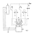
- Fig. 1 shows the basic structure of a control circuit for a 4-strand brushless DC motor, the stator winding is connected in a ring circuit. 1 contains all the elements that belong to the DC motor and not to the control circuit.
- 11 denotes a rotor covered with permanent magnetic material, 12, 13, 14 and 15 identify the four strands of the stator.
- 16 and 17 denote two magnetic field sensors which detect the position of the rotor 11. The two sensors 16 and 17 are connected to a commutation circuit 18.
- the output of the commutation circuit 18 is connected to a driver circuit 19 via lines labeled 20.
- 21 denotes a switch A+, 22 a switch B ⁇ , 23 a switch C+ and 24 a switch D ⁇ .
- the two switches A+ and C+ connect points A and C on the motor to the supply voltage.
- the switches B ⁇ and D ⁇ connect the points B and D to the ground.
- 25 a connection for the supply voltage is designated, with 26 a smoothing capacitor.
- FIG. 2 serves to explain the switching sequence of the arrangement according to FIG. 1 with simple commutation.
- the circle labeled 30 schematically identifies a stator of a brushless DC motor wound with four winding strands connected in a ring circuit.
- the points denoted by A, B, C and D correspond to the points A, B, C and D in FIG. 1.
- the arrows marked 31 in the circumferential direction show the direction of current flow in the individual strands in the respective switching state of the semiconductor switches.
- 32 denotes a flow vector resulting from this current distribution.
- a filled connection point A, B, C or D stands for the connection of this point with the supply voltage or with the ground.
- Second step switches A+ and D ⁇ are closed, the flow vector rotates 90 o further.
- Fourth step switches C+ and B ⁇ are closed, switches A+ and D ⁇ open.
- the first step is started again. It can be seen from the flow arrows in FIG. 2, designated 32, that a switching field is generated by this switching sequence, which drives the rotor of the machine.
- the flow pattern shown here refers to a two-pole machine in which an electrical angle of 2 pi corresponds to a machine angle of 2 pi. With a higher number of pole pairs and the same control sequence, the rotor rotates by an electrical angle of 2 Pi or by a spatial angle of 2 Pi / p with p equal to the number of poles of the motor.
- FIG. 1 The arrangement according to FIG. 1 can, however, be controlled in a different way.
- a Switching sequence hereinafter referred to as double commutation, is described with the aid of FIG. 3.
- the number of the schematically represented motors in the top line of FIG. 3 is twice as large as in FIG. 2.
- the designations of the connections, the current flow in the individual lines and the resulting flow vector are as in FIG. 2.
- First step switches A+ and B ⁇ closed, switches C+ and D ⁇ open
- second step switches A+, B ⁇ and D ⁇ closed, switch C+ open
- third step switches A+ and D ⁇ closed, switches C+ and B ⁇ open
- fourth step switches A+, C+ and D ⁇ closed, switch B ⁇ open
- fifth step switches C+ and D ⁇ closed, switches A+ and B ⁇ open
- sixth step switches C+, B ⁇ and D ⁇ closed, switch A+ open
- seventh step switches C+ and B ⁇ closed, switches A+ and D ⁇ open
- Eighth step switches A+, C+ and B ⁇ closed, switch D ⁇ open.
Landscapes
- Engineering & Computer Science (AREA)
- Power Engineering (AREA)
- Control Of Motors That Do Not Use Commutators (AREA)
Applications Claiming Priority (2)
| Application Number | Priority Date | Filing Date | Title |
|---|---|---|---|
| DE3817423 | 1988-05-21 | ||
| DE3817423A DE3817423A1 (de) | 1988-05-21 | 1988-05-21 | Vorrichtung und verfahren zur steuerung von buerstenlosen 4-straengigen gleichstrommotoren |
Publications (2)
| Publication Number | Publication Date |
|---|---|
| EP0343481A2 true EP0343481A2 (fr) | 1989-11-29 |
| EP0343481A3 EP0343481A3 (fr) | 1990-05-23 |
Family
ID=6354902
Family Applications (1)
| Application Number | Title | Priority Date | Filing Date |
|---|---|---|---|
| EP89108717A Withdrawn EP0343481A3 (fr) | 1988-05-21 | 1989-05-16 | Dispositif et procédé pour contrôler des moteurs à courant continu sans balais tétraphasé |
Country Status (4)
| Country | Link |
|---|---|
| US (1) | US5043641A (fr) |
| EP (1) | EP0343481A3 (fr) |
| JP (1) | JPH0223088A (fr) |
| DE (1) | DE3817423A1 (fr) |
Cited By (1)
| Publication number | Priority date | Publication date | Assignee | Title |
|---|---|---|---|---|
| WO2005095765A1 (fr) * | 2004-03-26 | 2005-10-13 | Schaeffler Kg | Dispositif de reglage electrique d'arbres a cames avec moteur a entrefer plat |
Families Citing this family (6)
| Publication number | Priority date | Publication date | Assignee | Title |
|---|---|---|---|---|
| US5737210A (en) * | 1996-04-30 | 1998-04-07 | Magnetek, Inc. | Bridge rectifier configuration and mounting for supplying exciter current in an AC generator |
| WO2003042999A1 (fr) * | 2001-11-10 | 2003-05-22 | Robert Bosch Gmbh | Moteur à commutation électronique |
| KR100725758B1 (ko) * | 2004-03-30 | 2007-06-08 | 삼성광주전자 주식회사 | 전동 송풍기 및 이를 이용한 자동차용 전동 과급기 |
| KR20050105315A (ko) * | 2004-04-28 | 2005-11-04 | 엘지전자 주식회사 | 냉장고 얼음이송장치의 제어회로 |
| FR2901927B1 (fr) * | 2006-06-01 | 2014-07-04 | Valeo Equip Electr Moteur | Machine tournante electrique triphasee |
| DE102018201340B3 (de) * | 2018-01-30 | 2019-06-13 | Bayerische Motoren Werke Aktiengesellschaft | Verfahren zum Betreiben einer Drehfeldmaschine eines Kraftfahrzeugs, Übertragungsvorrichtung, Antriebseinheit sowie Kraftfahrzeug |
Family Cites Families (10)
| Publication number | Priority date | Publication date | Assignee | Title |
|---|---|---|---|---|
| US3831072A (en) * | 1972-02-21 | 1974-08-20 | Canon Kk | Dc motor with hall generators |
| JPS5812566A (ja) * | 1981-07-14 | 1983-01-24 | Yoshiteru Takahashi | 電機子巻線を7個以上有するブラシレスモ−タ |
| JPS5851790A (ja) * | 1981-09-19 | 1983-03-26 | Victor Co Of Japan Ltd | 直流無刷子電動機 |
| JPS58127586A (ja) * | 1982-01-22 | 1983-07-29 | Victor Co Of Japan Ltd | 直流無整流子電動機 |
| US4689532A (en) * | 1985-05-07 | 1987-08-25 | Howlett James F | Ferritic sensor, self-controlled synchronous motor |
| DE3528765A1 (de) * | 1985-08-10 | 1987-02-19 | Bosch Gmbh Robert | Schaltungsanordnung fuer einen buerstenlosen gleichstrommotor |
| NL8503249A (nl) * | 1985-11-26 | 1987-06-16 | Philips Nv | Borstelloze gelijkstroommotor. |
| US4703235A (en) * | 1986-12-03 | 1987-10-27 | United Technologies Corporation | Brushless DC motor |
| DE3710659A1 (de) * | 1987-03-31 | 1988-10-13 | Standard Elektrik Lorenz Ag | Elektronisch kommutierter, kollektorloser gleichstrommotor |
| DE3710658A1 (de) * | 1987-03-31 | 1988-10-13 | Standard Elektrik Lorenz Ag | Elektronisch kommutierter, kollektorloser gleichstrommotor |
-
1988
- 1988-05-21 DE DE3817423A patent/DE3817423A1/de not_active Withdrawn
-
1989
- 1989-04-13 US US07/337,482 patent/US5043641A/en not_active Expired - Fee Related
- 1989-05-16 EP EP89108717A patent/EP0343481A3/fr not_active Withdrawn
- 1989-05-22 JP JP1128619A patent/JPH0223088A/ja active Pending
Cited By (1)
| Publication number | Priority date | Publication date | Assignee | Title |
|---|---|---|---|---|
| WO2005095765A1 (fr) * | 2004-03-26 | 2005-10-13 | Schaeffler Kg | Dispositif de reglage electrique d'arbres a cames avec moteur a entrefer plat |
Also Published As
| Publication number | Publication date |
|---|---|
| DE3817423A1 (de) | 1989-11-23 |
| EP0343481A3 (fr) | 1990-05-23 |
| JPH0223088A (ja) | 1990-01-25 |
| US5043641A (en) | 1991-08-27 |
Similar Documents
| Publication | Publication Date | Title |
|---|---|---|
| DE3812638C2 (de) | Bürstenloser bipolarer Mehrphasen-Gleichstrommotor | |
| DE69716086T2 (de) | Elektrische maschinen | |
| DE3490616C2 (fr) | ||
| DE69201354T2 (de) | Synchronmotor mit zwei dauermagnetischen Läuferteilen. | |
| DE69720945T2 (de) | Elektrische Maschine synchroner Bauart | |
| DE69100430T2 (de) | Synchron-Induktionsmotor mit Doppelstator. | |
| DE60007878T2 (de) | Ansteuerung einer elektrischen reluktanz maschine | |
| DE69916476T2 (de) | Synchronmaschine mit rotierenden bürsten | |
| DE3233096A1 (de) | Elektronisch kommutierter motor, waschmaschine, verfahren zum betreiben derselben, steuerschaltung und waschmaschinenantrieb | |
| DE1964229A1 (de) | Buerstenloser Gleichstrommotor | |
| DE2527744A1 (de) | Elektronisch kommutierter motor und verfahren zu seiner herstellung | |
| DE2305163A1 (de) | Buerstenloser gleichstrommotor | |
| DE102005014664A1 (de) | Elektrische Maschine | |
| DE10319394A1 (de) | Geschaltete Reluktanzmaschine, insbesondere SR-Motor | |
| DE102004030460B3 (de) | Elektromotorischer Antrieb für ein Fahrzeug | |
| DE4025713A1 (de) | Stromwendermotor | |
| EP0150070A2 (fr) | Moteur à courant continu sans collecteur à enroulement statorique sans fer | |
| EP0343481A2 (fr) | Dispositif et procédé pour contrôler des moteurs à courant continu sans balais tétraphasé | |
| DE19722453C1 (de) | Elektrisches Antriebssystem | |
| DE102020122142A1 (de) | Ein bürstenloser dc-dynamo und ein fahrzeug mit dem bürstenlosen dc-dynamo | |
| EP0664599B1 (fr) | Moteur à commutateur | |
| DE4330386A1 (de) | Geschalteter Reluktanzmotor | |
| DE1638569A1 (de) | Kollektorloser Gleichstrom-Kleinstmotor mit permanentmagneterregtem Laeufer | |
| DE3218740C2 (fr) | ||
| DE7310863U (de) | Kollektorloser gleichstrommotor |
Legal Events
| Date | Code | Title | Description |
|---|---|---|---|
| PUAI | Public reference made under article 153(3) epc to a published international application that has entered the european phase |
Free format text: ORIGINAL CODE: 0009012 |
|
| AK | Designated contracting states |
Kind code of ref document: A2 Designated state(s): CH DE ES GB IT LI |
|
| PUAL | Search report despatched |
Free format text: ORIGINAL CODE: 0009013 |
|
| AK | Designated contracting states |
Kind code of ref document: A3 Designated state(s): CH DE ES GB IT LI |
|
| 17P | Request for examination filed |
Effective date: 19900925 |
|
| RAP3 | Party data changed (applicant data changed or rights of an application transferred) |
Owner name: ALCATEL SEL AKTIENGESELLSCHAFT |
|
| 17Q | First examination report despatched |
Effective date: 19921120 |
|
| STAA | Information on the status of an ep patent application or granted ep patent |
Free format text: STATUS: THE APPLICATION HAS BEEN WITHDRAWN |
|
| 18W | Application withdrawn |
Withdrawal date: 19930428 |