EP0343511A2 - Procédé pour la fabrication de pièces moulées en forme de coquille - Google Patents
Procédé pour la fabrication de pièces moulées en forme de coquille Download PDFInfo
- Publication number
- EP0343511A2 EP0343511A2 EP89108954A EP89108954A EP0343511A2 EP 0343511 A2 EP0343511 A2 EP 0343511A2 EP 89108954 A EP89108954 A EP 89108954A EP 89108954 A EP89108954 A EP 89108954A EP 0343511 A2 EP0343511 A2 EP 0343511A2
- Authority
- EP
- European Patent Office
- Prior art keywords
- layer
- cover layer
- mold
- base layer
- space
- Prior art date
- Legal status (The legal status is an assumption and is not a legal conclusion. Google has not performed a legal analysis and makes no representation as to the accuracy of the status listed.)
- Granted
Links
Images

Classifications
-
- B—PERFORMING OPERATIONS; TRANSPORTING
- B29—WORKING OF PLASTICS; WORKING OF SUBSTANCES IN A PLASTIC STATE IN GENERAL
- B29C—SHAPING OR JOINING OF PLASTICS; SHAPING OF MATERIAL IN A PLASTIC STATE, NOT OTHERWISE PROVIDED FOR; AFTER-TREATMENT OF THE SHAPED PRODUCTS, e.g. REPAIRING
- B29C43/00—Compression moulding, i.e. applying external pressure to flow the moulding material; Apparatus therefor
- B29C43/02—Compression moulding, i.e. applying external pressure to flow the moulding material; Apparatus therefor of articles of definite length, i.e. discrete articles
- B29C43/14—Compression moulding, i.e. applying external pressure to flow the moulding material; Apparatus therefor of articles of definite length, i.e. discrete articles in several steps
- B29C43/146—Compression moulding, i.e. applying external pressure to flow the moulding material; Apparatus therefor of articles of definite length, i.e. discrete articles in several steps for making multilayered articles
-
- B—PERFORMING OPERATIONS; TRANSPORTING
- B29—WORKING OF PLASTICS; WORKING OF SUBSTANCES IN A PLASTIC STATE IN GENERAL
- B29C—SHAPING OR JOINING OF PLASTICS; SHAPING OF MATERIAL IN A PLASTIC STATE, NOT OTHERWISE PROVIDED FOR; AFTER-TREATMENT OF THE SHAPED PRODUCTS, e.g. REPAIRING
- B29C43/00—Compression moulding, i.e. applying external pressure to flow the moulding material; Apparatus therefor
- B29C43/02—Compression moulding, i.e. applying external pressure to flow the moulding material; Apparatus therefor of articles of definite length, i.e. discrete articles
- B29C43/10—Isostatic pressing, i.e. using non-rigid pressure-exerting members against rigid parts or dies
- B29C43/12—Isostatic pressing, i.e. using non-rigid pressure-exerting members against rigid parts or dies using bags surrounding the moulding material or using membranes contacting the moulding material
-
- B—PERFORMING OPERATIONS; TRANSPORTING
- B29—WORKING OF PLASTICS; WORKING OF SUBSTANCES IN A PLASTIC STATE IN GENERAL
- B29C—SHAPING OR JOINING OF PLASTICS; SHAPING OF MATERIAL IN A PLASTIC STATE, NOT OTHERWISE PROVIDED FOR; AFTER-TREATMENT OF THE SHAPED PRODUCTS, e.g. REPAIRING
- B29C43/00—Compression moulding, i.e. applying external pressure to flow the moulding material; Apparatus therefor
- B29C43/02—Compression moulding, i.e. applying external pressure to flow the moulding material; Apparatus therefor of articles of definite length, i.e. discrete articles
- B29C43/20—Making multilayered or multicoloured articles
- B29C43/203—Making multilayered articles
- B29C43/206—Making multilayered articles by pressing the material between two preformed layers, e.g. deformable layers
-
- B—PERFORMING OPERATIONS; TRANSPORTING
- B29—WORKING OF PLASTICS; WORKING OF SUBSTANCES IN A PLASTIC STATE IN GENERAL
- B29C—SHAPING OR JOINING OF PLASTICS; SHAPING OF MATERIAL IN A PLASTIC STATE, NOT OTHERWISE PROVIDED FOR; AFTER-TREATMENT OF THE SHAPED PRODUCTS, e.g. REPAIRING
- B29C51/00—Shaping by thermoforming, i.e. shaping sheets or sheet like preforms after heating, e.g. shaping sheets in matched moulds or by deep-drawing; Apparatus therefor
- B29C51/14—Shaping by thermoforming, i.e. shaping sheets or sheet like preforms after heating, e.g. shaping sheets in matched moulds or by deep-drawing; Apparatus therefor using multilayered preforms or sheets
- B29C51/145—Shaping by thermoforming, i.e. shaping sheets or sheet like preforms after heating, e.g. shaping sheets in matched moulds or by deep-drawing; Apparatus therefor using multilayered preforms or sheets having at least one layer of textile or fibrous material combined with at least one plastics layer
-
- B—PERFORMING OPERATIONS; TRANSPORTING
- B29—WORKING OF PLASTICS; WORKING OF SUBSTANCES IN A PLASTIC STATE IN GENERAL
- B29C—SHAPING OR JOINING OF PLASTICS; SHAPING OF MATERIAL IN A PLASTIC STATE, NOT OTHERWISE PROVIDED FOR; AFTER-TREATMENT OF THE SHAPED PRODUCTS, e.g. REPAIRING
- B29C70/00—Shaping composites, i.e. plastics material comprising reinforcements, fillers or preformed parts, e.g. inserts
- B29C70/04—Shaping composites, i.e. plastics material comprising reinforcements, fillers or preformed parts, e.g. inserts comprising reinforcements only, e.g. self-reinforcing plastics
- B29C70/28—Shaping operations therefor
- B29C70/54—Component parts, details or accessories; Auxiliary operations, e.g. feeding or storage of prepregs or SMC after impregnation or during ageing
- B29C70/542—Placing or positioning the reinforcement in a covering or packaging element before or during moulding, e.g. drawing in a sleeve
-
- B—PERFORMING OPERATIONS; TRANSPORTING
- B29—WORKING OF PLASTICS; WORKING OF SUBSTANCES IN A PLASTIC STATE IN GENERAL
- B29C—SHAPING OR JOINING OF PLASTICS; SHAPING OF MATERIAL IN A PLASTIC STATE, NOT OTHERWISE PROVIDED FOR; AFTER-TREATMENT OF THE SHAPED PRODUCTS, e.g. REPAIRING
- B29C43/00—Compression moulding, i.e. applying external pressure to flow the moulding material; Apparatus therefor
- B29C43/32—Component parts, details or accessories; Auxiliary operations
- B29C43/36—Moulds for making articles of definite length, i.e. discrete articles
- B29C43/3642—Bags, bleeder sheets or cauls for isostatic pressing
- B29C2043/3644—Vacuum bags; Details thereof, e.g. fixing or clamping
-
- B—PERFORMING OPERATIONS; TRANSPORTING
- B29—WORKING OF PLASTICS; WORKING OF SUBSTANCES IN A PLASTIC STATE IN GENERAL
- B29C—SHAPING OR JOINING OF PLASTICS; SHAPING OF MATERIAL IN A PLASTIC STATE, NOT OTHERWISE PROVIDED FOR; AFTER-TREATMENT OF THE SHAPED PRODUCTS, e.g. REPAIRING
- B29C43/00—Compression moulding, i.e. applying external pressure to flow the moulding material; Apparatus therefor
- B29C43/32—Component parts, details or accessories; Auxiliary operations
- B29C43/36—Moulds for making articles of definite length, i.e. discrete articles
- B29C43/3642—Bags, bleeder sheets or cauls for isostatic pressing
- B29C2043/3647—Membranes, diaphragms
-
- B—PERFORMING OPERATIONS; TRANSPORTING
- B29—WORKING OF PLASTICS; WORKING OF SUBSTANCES IN A PLASTIC STATE IN GENERAL
- B29C—SHAPING OR JOINING OF PLASTICS; SHAPING OF MATERIAL IN A PLASTIC STATE, NOT OTHERWISE PROVIDED FOR; AFTER-TREATMENT OF THE SHAPED PRODUCTS, e.g. REPAIRING
- B29C33/00—Moulds or cores; Details thereof or accessories therefor
- B29C33/10—Moulds or cores; Details thereof or accessories therefor with incorporated venting means
-
- B—PERFORMING OPERATIONS; TRANSPORTING
- B29—WORKING OF PLASTICS; WORKING OF SUBSTANCES IN A PLASTIC STATE IN GENERAL
- B29C—SHAPING OR JOINING OF PLASTICS; SHAPING OF MATERIAL IN A PLASTIC STATE, NOT OTHERWISE PROVIDED FOR; AFTER-TREATMENT OF THE SHAPED PRODUCTS, e.g. REPAIRING
- B29C33/00—Moulds or cores; Details thereof or accessories therefor
- B29C33/56—Coatings, e.g. enameled or galvanised; Releasing, lubricating or separating agents
- B29C33/68—Release sheets
-
- B—PERFORMING OPERATIONS; TRANSPORTING
- B29—WORKING OF PLASTICS; WORKING OF SUBSTANCES IN A PLASTIC STATE IN GENERAL
- B29C—SHAPING OR JOINING OF PLASTICS; SHAPING OF MATERIAL IN A PLASTIC STATE, NOT OTHERWISE PROVIDED FOR; AFTER-TREATMENT OF THE SHAPED PRODUCTS, e.g. REPAIRING
- B29C51/00—Shaping by thermoforming, i.e. shaping sheets or sheet like preforms after heating, e.g. shaping sheets in matched moulds or by deep-drawing; Apparatus therefor
- B29C51/08—Deep drawing or matched-mould forming, i.e. using mechanical means only
- B29C51/082—Deep drawing or matched-mould forming, i.e. using mechanical means only by shaping between complementary mould parts
-
- B—PERFORMING OPERATIONS; TRANSPORTING
- B29—WORKING OF PLASTICS; WORKING OF SUBSTANCES IN A PLASTIC STATE IN GENERAL
- B29K—INDEXING SCHEME ASSOCIATED WITH SUBCLASSES B29B, B29C OR B29D, RELATING TO MOULDING MATERIALS OR TO MATERIALS FOR MOULDS, REINFORCEMENTS, FILLERS OR PREFORMED PARTS, e.g. INSERTS
- B29K2105/00—Condition, form or state of moulded material or of the material to be shaped
- B29K2105/06—Condition, form or state of moulded material or of the material to be shaped containing reinforcements, fillers or inserts
- B29K2105/08—Condition, form or state of moulded material or of the material to be shaped containing reinforcements, fillers or inserts of continuous length, e.g. cords, rovings, mats, fabrics, strands or yarns
- B29K2105/0854—Condition, form or state of moulded material or of the material to be shaped containing reinforcements, fillers or inserts of continuous length, e.g. cords, rovings, mats, fabrics, strands or yarns in the form of a non-woven mat
-
- B—PERFORMING OPERATIONS; TRANSPORTING
- B29—WORKING OF PLASTICS; WORKING OF SUBSTANCES IN A PLASTIC STATE IN GENERAL
- B29K—INDEXING SCHEME ASSOCIATED WITH SUBCLASSES B29B, B29C OR B29D, RELATING TO MOULDING MATERIALS OR TO MATERIALS FOR MOULDS, REINFORCEMENTS, FILLERS OR PREFORMED PARTS, e.g. INSERTS
- B29K2105/00—Condition, form or state of moulded material or of the material to be shaped
- B29K2105/25—Solid
- B29K2105/253—Preform
- B29K2105/256—Sheets, plates, blanks or films
-
- B—PERFORMING OPERATIONS; TRANSPORTING
- B29—WORKING OF PLASTICS; WORKING OF SUBSTANCES IN A PLASTIC STATE IN GENERAL
- B29L—INDEXING SCHEME ASSOCIATED WITH SUBCLASS B29C, RELATING TO PARTICULAR ARTICLES
- B29L2031/00—Other particular articles
- B29L2031/712—Containers; Packaging elements or accessories, Packages
Definitions
- the invention relates to a method for producing a shell-like molded part, the wall of which, in a positive and / or negative form, consists of a fiber-reinforced base layer made of a liquid synthetic resin with hardener and at least one cover layer arranged on one side of the base layer and integrally connected to it modified, liquid synthetic resin is formed.
- the actual base layer is produced on it by placing one or more fiber mats impregnated with a hardenable plastic, for example glass fiber or carbon fiber mats, and, if necessary, additionally coating or impregnating the hardenable plastic.
- a hardenable plastic for example glass fiber or carbon fiber mats
- the shell-like molded part, the edges of which still have to be processed is finished.
- Such a manual laminate process is used in particular for small series and special designs.
- high emissions occur due to the release agent, but especially due to the high proportion of styrene in the plastic of the cover layer, which are difficult to extract and require additional cleaning.
- the invention is based on the object of specifying a method for producing a shell-like molded part according to the preamble of claim 1, in which the workload for producing the cover layer is reduced and the styrene emission is considerably reduced.
- the wall thickness of the cover layer should be kept as constant as possible so that no unnecessary, valuable material is used.
- the method also creates the possibility that a top or fine layer can be applied to an already produced base layer of a molded part and thus a special surface treatment process, in particular painting process, is not necessary.
- a deformable space is formed between the mold and the base layer, that a predetermined amount of the liquid synthetic resin required for the cover layer is filled and that this space is then passed through Deformed pressure and / or vacuum and thereby the cover layer is formed. Due to the deformable, at least largely closed space, no emissions occur during the formation of the cover layer.
- the cover layer is produced in a relatively short time and with approximately the same wall thickness, so that the labor and material costs are also reduced.
- This method also makes it possible to produce the cover layer on the already finished base layer or a so-called raw component. Since the formation of the cover layer takes place very quickly, hardening can also start in a very short time, so that the cover layer is cured or finished in a relatively short time.
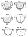
- a shape 1 is shown with a trapezoidal cross section, which is made of wood, for example, and which has a flange 2 in its upper region for receiving an intermediate part 3.
- the interior of the mold 1 is provided with a separating layer, not shown, which is formed, for example, from wax or from silicone oil.
- a separating layer not shown, which is formed, for example, from wax or from silicone oil.
- channels not shown in the drawing are provided, to which at least one known vacuum pump can be connected.
- a predetermined amount of a modified, liquid plastic 6 is applied to the mold base (FIG. 1), which is required to form a cover layer 7 covering the interior of the mold 1.
- an intermediate space 5 formed in this way is evacuated in a relatively short time.
- the preformed film 4 initially lies inward towards the bottom of the mold 1, where it comes to rest on the liquid plastic 6.
- the liquid plastic 6 with an approximately uniform wall thickness is distributed through the preformed film 4 over the inner surface of the mold 1 until the closed cover layer 7 according to FIG. 2 has formed.
- the space 5 has deformed or shrunk so that its volume corresponds exactly to the volume of the liquid plastic 6.
- the intermediate space 5 is completely filled with the liquid plastic 6 or the cover layer 7.
- the preformed film 4 or the raw component ensures that no uncontrollable emissions escape to the outside during the formation of the cover layer 7.
- the cover layer 7 As soon as the cover layer 7 has reached a predetermined curing due to a hardener in the liquid plastic 6, the thin, preformed film 4, which is used exclusively to form the cover layer 7, is removed.
- a base layer (not shown) made of fiber-reinforced plastic is then produced on the cover layer 7 in a manner known per se.
- This base layer can be produced in the way that first the inner wall of the mold 1 or the cover layer 7 is covered with fiber mats. Then, after the liquid plastic quantity required for the base layer has been filled into the mold 1, the mold 1 is closed again by a film. By evacuating the space 5 between the film, which is similar to the film 4, and the cover layer 7, this film is also pulled inwards.
- the filled synthetic resin composition is evenly distributed over the cover layer 7, the fiber mats are soaked in the synthetic resin composition and the base layer is formed.
- the device for forming a cover layer 7 consists of a base plate 8, on which either a mold or a so-called raw component 9 is arranged.
- This shell component 9 is formed by the fiber-reinforced base layer of a molded part, which is to be provided on its outer surface with a cover layer 7.
- a flange 10 is provided over the base plate 8, which is covered with a deformable or deep-drawn film 4.
- a layer of liquid plastic 6, which serves to form the cover layer 7, is applied to the surface of the film 4 facing the base plate 8. If necessary, this plastic 6 can also be applied in the area of the upper surface of the raw component 9.
- the film 4 is deformed and the cover layer 7 is formed on the raw component 9 (FIG. 4).
- 8 holes 11 can be arranged in the base plate, through which the space 5 between the unfinished component 9 and the film 4 is evacuated, which improves the uniformity of the wall thickness of the cover layer 7.
- a special drive for the flange 10 can then be omitted.
- the finished molded part 12 (FIG. 4) has a subsequently applied top layer 7, which has a very smooth and perfect surface due to the film 4, which normally does not have to be reworked.
- an intermediate part 3 is inserted into the mold 1 in the region of the flange 2, which projects into the free surface of the mold 1 by a predetermined amount.
- a liquid plastic 6 is poured into the mold 1 coated with a release agent, which is distributed evenly over the inner surface of the mold 1 by a film 4 and vacuum placed on the intermediate part 3 and thus forms the cover layer 7, which is only indicated.
- the film 4 is removed.
- the fiber-reinforced base layer is then produced on the cover layer 7 in a manner known per se. If necessary, this base layer can extend over the intermediate part 3.
- FIG. 6 essentially corresponds to the embodiment of FIG. 1.
- the mold 1 has an additional separating layer 13 which is formed from a plastic film. This plastic film was sealingly attached to the flange 2 or the intermediate part 3 and then brought into contact by evacuation on the inner wall of the mold 1 and the intermediate part 3. The cover layer 7 is then produced on this separating layer 13, as explained with reference to FIG. 5.
- a counterpart 1a is assigned to shape 1.
- both the inside of the mold 1 and the outside of the counterpart 1a are each provided with a separating layer 13, which consists of a thermoformable plastic film. These separating layers 13 are brought into contact with the mold 1 as well as with the counterpart 1a by vacuum (FIG. 8).
- a raw component 9 is provided with a cover layer 7 both on its inner surface and on its outer surface.
- a liquid plastic 6 for the outer cover layer 7 is first filled into the mold 1.
- the raw component 9, in which there is already a liquid plastic 6a for forming the inner cover layer 7, is then inserted into the mold 1.
- the counterpart 1a is pressed into the mold 1, the cover layers 7 being formed from the plastics 6 and 6a and completely enclosing the raw component 9. If necessary, it is possible to connect the counterpart 1a airtight to the mold 1 and to evacuate the space 5 between the mold 1 and the counterpart 1a. Here too, the liquid plastics 6 and 6a form a flawless cover layer 7 on the outer surface and the inner surface of the unfinished component 9, which no longer has to be processed.
- a counterpart 1a is assigned to shape 1.
- the mutually facing surfaces of the mold 1 and the counterpart 1a are provided with a separating layer 13 made of a thermoformable film.
- a projection 14 is incorporated into the mold 1, while the counterpart 1a has a corresponding recess 14a. Both the projection 14 and the depression 14a are covered by the separating layer 13 or the plastic film.
- a liquid is formed in the mold 1 provided with the separating layer 13 Plastic 6 filled, which serves to form a cover layer 7.
- either the counterpart 1a is pressed into the mold 1 or the space 5 between the mold 1 and the counterpart 1a is evacuated. It is necessary that the outer edges of the mold 1 and the counterpart 1a are airtight. If necessary, pressure and vacuum can also be used simultaneously to produce the cover layer 7.
- the mold 1 is also coated with a separating layer 13 made of a deep-drawn film.
- a raw component 9 is inserted into it, which in its upper region is sealingly connected to the flange 2 of the mold 1, for example via a film 15.
- the air is now sucked out of the space 5 formed between the raw component 9 and the mold 1 or separating layer 13 via bores or channels, not shown.
- the raw component 9 is pulled against the mold 1 and a cover layer 7 is formed on the outer surface of the raw component 9.
- the raw component 9 also consists of a non-reinforced (e.g. polyester concrete) or fiber-reinforced base layer.
- the exemplary embodiment in FIG. 11 largely corresponds to the exemplary embodiment in FIG. 10.
- the separating layer 13 is not applied directly to the inner surface of the mold 1.
- an elastic layer 16 for example made of foam rubber, which ensures an intermediate space for the fine layer to be applied later in the same working form during the production of the raw component 9.
- a separating layer 13 and a film 4 are applied in a sealing manner on the flange 2 of the mold 1, a liquid plastic 6 being filled into the space 5 between the separating layer 13 and the film 4 to form a cover layer 7 and by means of a vacuum is evacuated.
- a second vacuum the separating layer 13 is brought to bear against the inner wall of the mold 1.
- the film 4 also deforms in a similar manner, a cover layer being formed between the separating layer 13 and the film 4.
- the film 4 is removed and, as explained with reference to FIGS. 1 and 2, the fiber-reinforced base layer is applied to the cover layer.
Landscapes
- Engineering & Computer Science (AREA)
- Mechanical Engineering (AREA)
- Textile Engineering (AREA)
- Chemical & Material Sciences (AREA)
- Composite Materials (AREA)
- Casting Or Compression Moulding Of Plastics Or The Like (AREA)
- Moulds For Moulding Plastics Or The Like (AREA)
- Blow-Moulding Or Thermoforming Of Plastics Or The Like (AREA)
- Materials For Medical Uses (AREA)
- Moulding By Coating Moulds (AREA)
- Peptides Or Proteins (AREA)
- Investigating Or Analysing Materials By The Use Of Chemical Reactions (AREA)
- Respiratory Apparatuses And Protective Means (AREA)
Priority Applications (1)
| Application Number | Priority Date | Filing Date | Title |
|---|---|---|---|
| AT89108954T ATE102866T1 (de) | 1988-05-24 | 1989-05-18 | Verfahren zur herstellung eines schalenartigen formteiles. |
Applications Claiming Priority (2)
| Application Number | Priority Date | Filing Date | Title |
|---|---|---|---|
| DE3817525A DE3817525A1 (de) | 1988-05-24 | 1988-05-24 | Verfahren zur herstellung eines schalenartigen formteiles |
| DE3817525 | 1988-05-24 |
Publications (3)
| Publication Number | Publication Date |
|---|---|
| EP0343511A2 true EP0343511A2 (fr) | 1989-11-29 |
| EP0343511A3 EP0343511A3 (fr) | 1991-01-23 |
| EP0343511B1 EP0343511B1 (fr) | 1994-03-16 |
Family
ID=6354970
Family Applications (1)
| Application Number | Title | Priority Date | Filing Date |
|---|---|---|---|
| EP89108954A Expired - Lifetime EP0343511B1 (fr) | 1988-05-24 | 1989-05-18 | Procédé pour la fabrication de pièces moulées en forme de coquille |
Country Status (4)
| Country | Link |
|---|---|
| EP (1) | EP0343511B1 (fr) |
| AT (1) | ATE102866T1 (fr) |
| DE (2) | DE3817525A1 (fr) |
| FI (1) | FI892490L (fr) |
Cited By (3)
| Publication number | Priority date | Publication date | Assignee | Title |
|---|---|---|---|---|
| WO1998045103A1 (fr) * | 1997-04-09 | 1998-10-15 | Dbs Beschichtung Und Systeme-Technik Gmbh | Procede pour produire des parois destinees a des profiles et a des objets fermes |
| EP1421918A1 (fr) * | 2002-11-19 | 2004-05-26 | Zimmer Technology, Inc. | Dispositif prothétique et méthode pour le fabriquer |
| EP2135537A1 (fr) * | 2003-07-25 | 2009-12-23 | Kohler Mira Limited | Article composite et procédé de fabrication |
Family Cites Families (8)
| Publication number | Priority date | Publication date | Assignee | Title |
|---|---|---|---|---|
| US3150792A (en) * | 1958-05-01 | 1964-09-29 | Air Logistics Corp | Reinforced plastic molded article and method of making same |
| NL299952A (fr) * | 1962-11-05 | |||
| US3597425A (en) * | 1969-04-14 | 1971-08-03 | American Standard Inc | Plastic molding process |
| GB1282306A (en) * | 1969-05-05 | 1972-07-19 | Ici Ltd | New casting process |
| CA1023913A (fr) * | 1973-09-04 | 1978-01-10 | General Tire And Rubber Company (The) | Compose de revetement sous moule et mode d'emploi |
| US4076788A (en) * | 1976-12-02 | 1978-02-28 | General Motors Corporation | Mold coating of freshly molded articles |
| DE2844612A1 (de) * | 1978-10-13 | 1980-04-24 | Herbold Werner R | Verfahren zum herstellen eines wenigstens aus zwei schichten bestehenden verbundwerkstoffs auf der basis duroplastischer kunststoffe und nach diesem verfahren hergestelltes formteil |
| DE229441T1 (de) * | 1986-01-10 | 1988-02-04 | Group Lotus Plc, Norwich, Norfolk | Verfahren zum formen eines gegenstandes. |
-
1988
- 1988-05-24 DE DE3817525A patent/DE3817525A1/de not_active Withdrawn
-
1989
- 1989-05-18 DE DE89108954T patent/DE58907201D1/de not_active Expired - Fee Related
- 1989-05-18 AT AT89108954T patent/ATE102866T1/de not_active IP Right Cessation
- 1989-05-18 EP EP89108954A patent/EP0343511B1/fr not_active Expired - Lifetime
- 1989-05-23 FI FI892490A patent/FI892490L/fi not_active IP Right Cessation
Cited By (4)
| Publication number | Priority date | Publication date | Assignee | Title |
|---|---|---|---|---|
| WO1998045103A1 (fr) * | 1997-04-09 | 1998-10-15 | Dbs Beschichtung Und Systeme-Technik Gmbh | Procede pour produire des parois destinees a des profiles et a des objets fermes |
| EP1421918A1 (fr) * | 2002-11-19 | 2004-05-26 | Zimmer Technology, Inc. | Dispositif prothétique et méthode pour le fabriquer |
| US6976999B2 (en) | 2002-11-19 | 2005-12-20 | Zimmer Technology, Inc. | Prosthetic device and method of making the same |
| EP2135537A1 (fr) * | 2003-07-25 | 2009-12-23 | Kohler Mira Limited | Article composite et procédé de fabrication |
Also Published As
| Publication number | Publication date |
|---|---|
| ATE102866T1 (de) | 1994-04-15 |
| EP0343511B1 (fr) | 1994-03-16 |
| FI892490A0 (fi) | 1989-05-23 |
| EP0343511A3 (fr) | 1991-01-23 |
| DE3817525A1 (de) | 1989-12-07 |
| FI892490A7 (fi) | 1989-11-25 |
| DE58907201D1 (de) | 1994-04-21 |
| FI892490L (fi) | 1989-11-25 |
Similar Documents
| Publication | Publication Date | Title |
|---|---|---|
| DE68918186T2 (de) | Form und Verfahren zum Formpressen von faserverstärkten Kunststoffteilen. | |
| DE69207906T2 (de) | Verfahren zum herstellen einer verbundkonstruktion mit einem zwischenliegenden, raeumlich verzweigten gewebe, und nach dem verfahren hergestellte verbundkonstruktion | |
| DE4019744A1 (de) | Verfahren zum reparieren von bauteilen aus kunststoff, insbesondere aus faserverbundwerkstoffen | |
| DE2548739A1 (de) | Verfahren zur herstellung von gepressten profilkoerpern aus einem nicht steigfaehigen gemisch | |
| DE3821941A1 (de) | Verfahren und vorrichtung zur herstellung von formteilen aus aushaertbarem werkstoff | |
| EP1239975A2 (fr) | Procede et dispositif de revetement de surface d'un element de construction interne de vehicules automobiles | |
| DE3438312A1 (de) | Laengstraegerelement fuer hubschrauber-rotorblaetter und verfahren zur herstellung desselben | |
| DE10124122C1 (de) | Verfahren und Vorrichtung zum Herstellen eines faserverstärkten Kunststoffteils | |
| EP1238784A1 (fr) | Objet profilé en forme de coquille, procédé de fabrication et moule pour l'obtenir | |
| DE102013222356B4 (de) | Verfahren zum Herstellen eines integralen Faserverbundbauteils mit Einlegeelement | |
| DE2547499B2 (de) | Verfahren zum Befestigen einer mit einem Flor versehenen Auflage auf einem Träger | |
| DE102012013538B4 (de) | Verfahren zur Herstellung von Sandwichelementen | |
| DE3536272C2 (fr) | ||
| EP0343511B1 (fr) | Procédé pour la fabrication de pièces moulées en forme de coquille | |
| DE102013216863A1 (de) | Werkzeugsystem und Verfahren zur Herstellung von Bauteilen nach dem RTM-Verfahren | |
| DE1214388B (de) | Verfahren zum Herstellen von gewoelbten Koerpern aus glasfaserverstaerktem Kunstharz | |
| EP0325690B1 (fr) | Procédé de fabrication d'une pièce en contre-plaqué avec placage en bois et l'outil de poinçonnage pour sa mise en oeuvre et produit ainsi obtenu | |
| DE2719128A1 (de) | Verfahren zum anbringen einer kunststoffumrandung fuer schnittflaechen von platten und vorrichtung zur durchfuehrung des verfahrens sowie nach dem verfahren hergestellte platte | |
| DE3149599C2 (de) | Vorrichtung zum Umspritzen umlaufender Schnittkanten von Platten aus Holzwerkstoff | |
| DE102013222425B4 (de) | Presswerkzeug und Verfahren zum Verpressen eines Materialverbundes | |
| DE3033494A1 (de) | Verfahren zum herstellen von formteilen und vorrichtung zur durchfuehrung des verfahrens | |
| DE102019119479B4 (de) | Verfahren zur Herstellung eines Isolierpaneels | |
| EP2409823A2 (fr) | Procédé et dispositif de fabrication d'un élément de décor et élément de décor | |
| DE19829859A1 (de) | Verfahren zur Herstellung einer lackierfähigen Basisschicht auf einer Außenhaut eines Kunststoffbauteils und danach hergestelltes Bauteil | |
| DE102019116817B4 (de) | Verfahren und Vorrichtung zur Herstellung eines Profilbauteils |
Legal Events
| Date | Code | Title | Description |
|---|---|---|---|
| PUAI | Public reference made under article 153(3) epc to a published international application that has entered the european phase |
Free format text: ORIGINAL CODE: 0009012 |
|
| AK | Designated contracting states |
Kind code of ref document: A2 Designated state(s): AT BE CH DE ES FR GB GR IT LI NL SE |
|
| PUAL | Search report despatched |
Free format text: ORIGINAL CODE: 0009013 |
|
| AK | Designated contracting states |
Kind code of ref document: A3 Designated state(s): AT BE CH DE ES FR GB GR IT LI NL SE |
|
| 17P | Request for examination filed |
Effective date: 19910719 |
|
| 17Q | First examination report despatched |
Effective date: 19920717 |
|
| GRAA | (expected) grant |
Free format text: ORIGINAL CODE: 0009210 |
|
| AK | Designated contracting states |
Kind code of ref document: B1 Designated state(s): AT BE CH DE ES FR GB GR IT LI NL SE |
|
| PG25 | Lapsed in a contracting state [announced via postgrant information from national office to epo] |
Ref country code: IT Free format text: LAPSE BECAUSE OF FAILURE TO SUBMIT A TRANSLATION OF THE DESCRIPTION OR TO PAY THE FEE WITHIN THE PRE;WARNING: LAPSES OF ITALIAN PATENTS WITH EFFECTIVE DATE BEFORE 2007 MAY HAVE OCCURRED AT ANY TIME BEFORE 2007. THE CORRECT EFFECTIVE DATE MAY BE DIFFERENT FROM THE ONE RECORDED.SCRIBED TIME-LIMIT Effective date: 19940316 Ref country code: BE Effective date: 19940316 Ref country code: FR Effective date: 19940316 Ref country code: GB Effective date: 19940316 Ref country code: ES Free format text: THE PATENT HAS BEEN ANNULLED BY A DECISION OF A NATIONAL AUTHORITY Effective date: 19940316 Ref country code: SE Free format text: THE PATENT HAS BEEN ANNULLED BY A DECISION OF A NATIONAL AUTHORITY Effective date: 19940316 Ref country code: GR Free format text: LAPSE BECAUSE OF FAILURE TO SUBMIT A TRANSLATION OF THE DESCRIPTION OR TO PAY THE FEE WITHIN THE PRESCRIBED TIME-LIMIT Effective date: 19940316 Ref country code: NL Effective date: 19940316 |
|
| REF | Corresponds to: |
Ref document number: 102866 Country of ref document: AT Date of ref document: 19940415 Kind code of ref document: T |
|
| REF | Corresponds to: |
Ref document number: 58907201 Country of ref document: DE Date of ref document: 19940421 |
|
| PG25 | Lapsed in a contracting state [announced via postgrant information from national office to epo] |
Ref country code: AT Effective date: 19940518 |
|
| PG25 | Lapsed in a contracting state [announced via postgrant information from national office to epo] |
Ref country code: CH Effective date: 19940531 Ref country code: LI Effective date: 19940531 |
|
| EN | Fr: translation not filed | ||
| NLV1 | Nl: lapsed or annulled due to failure to fulfill the requirements of art. 29p and 29m of the patents act | ||
| GBV | Gb: ep patent (uk) treated as always having been void in accordance with gb section 77(7)/1977 [no translation filed] |
Effective date: 19940316 |
|
| PLBI | Opposition filed |
Free format text: ORIGINAL CODE: 0009260 |
|
| REG | Reference to a national code |
Ref country code: CH Ref legal event code: PL |
|
| 26 | Opposition filed |
Opponent name: VOSSCHEMIE GMBH Effective date: 19941215 |
|
| PLBO | Opposition rejected |
Free format text: ORIGINAL CODE: EPIDOS REJO |
|
| PLBN | Opposition rejected |
Free format text: ORIGINAL CODE: 0009273 |
|
| STAA | Information on the status of an ep patent application or granted ep patent |
Free format text: STATUS: OPPOSITION REJECTED |
|
| 27O | Opposition rejected |
Effective date: 19960625 |
|
| PGFP | Annual fee paid to national office [announced via postgrant information from national office to epo] |
Ref country code: DE Payment date: 20000727 Year of fee payment: 12 |
|
| PG25 | Lapsed in a contracting state [announced via postgrant information from national office to epo] |
Ref country code: DE Free format text: LAPSE BECAUSE OF NON-PAYMENT OF DUE FEES Effective date: 20020301 |