EP0343662A2 - Kompressionswärmeübertragungssysteme mit Rotationsverdrängung enthaltenden synthetischen hochfluorierten Kühlschmierölzusammensetzungen - Google Patents
Kompressionswärmeübertragungssysteme mit Rotationsverdrängung enthaltenden synthetischen hochfluorierten Kühlschmierölzusammensetzungen Download PDFInfo
- Publication number
- EP0343662A2 EP0343662A2 EP89109441A EP89109441A EP0343662A2 EP 0343662 A2 EP0343662 A2 EP 0343662A2 EP 89109441 A EP89109441 A EP 89109441A EP 89109441 A EP89109441 A EP 89109441A EP 0343662 A2 EP0343662 A2 EP 0343662A2
- Authority
- EP
- European Patent Office
- Prior art keywords
- oil
- compressor
- refrigerant
- evaporator
- range
- Prior art date
- Legal status (The legal status is an assumption and is not a legal conclusion. Google has not performed a legal analysis and makes no representation as to the accuracy of the status listed.)
- Granted
Links
Images


Classifications
-
- F—MECHANICAL ENGINEERING; LIGHTING; HEATING; WEAPONS; BLASTING
- F25—REFRIGERATION OR COOLING; COMBINED HEATING AND REFRIGERATION SYSTEMS; HEAT PUMP SYSTEMS; MANUFACTURE OR STORAGE OF ICE; LIQUEFACTION SOLIDIFICATION OF GASES
- F25B—REFRIGERATION MACHINES, PLANTS OR SYSTEMS; COMBINED HEATING AND REFRIGERATION SYSTEMS; HEAT PUMP SYSTEMS
- F25B31/00—Compressor arrangements
- F25B31/002—Lubrication
-
- C—CHEMISTRY; METALLURGY
- C09—DYES; PAINTS; POLISHES; NATURAL RESINS; ADHESIVES; COMPOSITIONS NOT OTHERWISE PROVIDED FOR; APPLICATIONS OF MATERIALS NOT OTHERWISE PROVIDED FOR
- C09K—MATERIALS FOR MISCELLANEOUS APPLICATIONS, NOT PROVIDED FOR ELSEWHERE
- C09K5/00—Heat-transfer, heat-exchange or heat-storage materials, e.g. refrigerants; Materials for the production of heat or cold by chemical reactions other than by combustion
- C09K5/02—Materials undergoing a change of physical state when used
- C09K5/04—Materials undergoing a change of physical state when used the change of state being from liquid to vapour or vice versa
- C09K5/041—Materials undergoing a change of physical state when used the change of state being from liquid to vapour or vice versa for compression-type refrigeration systems
- C09K5/044—Materials undergoing a change of physical state when used the change of state being from liquid to vapour or vice versa for compression-type refrigeration systems comprising halogenated compounds
- C09K5/045—Materials undergoing a change of physical state when used the change of state being from liquid to vapour or vice versa for compression-type refrigeration systems comprising halogenated compounds containing only fluorine as halogen
-
- C—CHEMISTRY; METALLURGY
- C10—PETROLEUM, GAS OR COKE INDUSTRIES; TECHNICAL GASES CONTAINING CARBON MONOXIDE; FUELS; LUBRICANTS; PEAT
- C10M—LUBRICATING COMPOSITIONS; USE OF CHEMICAL SUBSTANCES EITHER ALONE OR AS LUBRICATING INGREDIENTS IN A LUBRICATING COMPOSITION
- C10M171/00—Lubricating compositions characterised by purely physical criteria, e.g. containing as base-material, thickener or additive, ingredients which are characterised exclusively by their numerically specified physical properties, i.e. containing ingredients which are physically well-defined but for which the chemical nature is either unspecified or only very vaguely indicated
- C10M171/008—Lubricant compositions compatible with refrigerants
-
- C—CHEMISTRY; METALLURGY
- C09—DYES; PAINTS; POLISHES; NATURAL RESINS; ADHESIVES; COMPOSITIONS NOT OTHERWISE PROVIDED FOR; APPLICATIONS OF MATERIALS NOT OTHERWISE PROVIDED FOR
- C09K—MATERIALS FOR MISCELLANEOUS APPLICATIONS, NOT PROVIDED FOR ELSEWHERE
- C09K2205/00—Aspects relating to compounds used in compression type refrigeration systems
- C09K2205/24—Only one single fluoro component present
-
- F—MECHANICAL ENGINEERING; LIGHTING; HEATING; WEAPONS; BLASTING
- F04—POSITIVE - DISPLACEMENT MACHINES FOR LIQUIDS; PUMPS FOR LIQUIDS OR ELASTIC FLUIDS
- F04C—ROTARY-PISTON, OR OSCILLATING-PISTON, POSITIVE-DISPLACEMENT MACHINES FOR LIQUIDS; ROTARY-PISTON, OR OSCILLATING-PISTON, POSITIVE-DISPLACEMENT PUMPS
- F04C18/00—Rotary-piston pumps specially adapted for elastic fluids
- F04C18/08—Rotary-piston pumps specially adapted for elastic fluids of intermeshing-engagement type, i.e. with engagement of co-operating members similar to that of toothed gearing
- F04C18/12—Rotary-piston pumps specially adapted for elastic fluids of intermeshing-engagement type, i.e. with engagement of co-operating members similar to that of toothed gearing of other than internal-axis type
- F04C18/14—Rotary-piston pumps specially adapted for elastic fluids of intermeshing-engagement type, i.e. with engagement of co-operating members similar to that of toothed gearing of other than internal-axis type with toothed rotary pistons
- F04C18/16—Rotary-piston pumps specially adapted for elastic fluids of intermeshing-engagement type, i.e. with engagement of co-operating members similar to that of toothed gearing of other than internal-axis type with toothed rotary pistons with helical teeth, e.g. chevron-shaped, screw type
-
- F—MECHANICAL ENGINEERING; LIGHTING; HEATING; WEAPONS; BLASTING
- F04—POSITIVE - DISPLACEMENT MACHINES FOR LIQUIDS; PUMPS FOR LIQUIDS OR ELASTIC FLUIDS
- F04C—ROTARY-PISTON, OR OSCILLATING-PISTON, POSITIVE-DISPLACEMENT MACHINES FOR LIQUIDS; ROTARY-PISTON, OR OSCILLATING-PISTON, POSITIVE-DISPLACEMENT PUMPS
- F04C29/00—Component parts, details or accessories of pumps or pumping installations, not provided for in groups F04C18/00 - F04C28/00
- F04C29/02—Lubrication; Lubricant separation
-
- F—MECHANICAL ENGINEERING; LIGHTING; HEATING; WEAPONS; BLASTING
- F25—REFRIGERATION OR COOLING; COMBINED HEATING AND REFRIGERATION SYSTEMS; HEAT PUMP SYSTEMS; MANUFACTURE OR STORAGE OF ICE; LIQUEFACTION SOLIDIFICATION OF GASES
- F25B—REFRIGERATION MACHINES, PLANTS OR SYSTEMS; COMBINED HEATING AND REFRIGERATION SYSTEMS; HEAT PUMP SYSTEMS
- F25B1/00—Compression machines, plants or systems with non-reversible cycle
- F25B1/04—Compression machines, plants or systems with non-reversible cycle with compressor of rotary type
- F25B1/047—Compression machines, plants or systems with non-reversible cycle with compressor of rotary type of screw type
Definitions
- This invention relates to compression-refrigeration, air conditioning, and heat pump systems in which the refrigerant is compressed in a rotary displacement compressor, the outlet of the compressor is connected to a condenser, the inlet of the compressor is connected to an evaporator, oil is injected into the compressor by an oil injector, oil is separated from the refrigerant and recirculated to the oil injection mechanism, the refrigerant is a fluorinated, non-chlorinated hydrocarbon, and the base lubricant is a polyether polyol or monol.
- refrigerant R-134a 1,1,1,2-tetrafluoroethane, also known as refrigerant R-134a, which contains no chlorine or bromine, and does not pose a risk to stratospheric ozone.
- This refrigerant which can be manufactured by the method described in U.S. patent No. 4,311,863, is thought, accordingly, to be a refrigerant of the future, and it is expected that R-134a will be widely used in oil-flooded rotary displacement compressors.
- liquid refrigerant flows from the condenser under pressure through the expansion valve to the evaporator coils where it evaporates, absorbing heat and cooling the room or other space where cooling is desired.
- the vapor is then drawn into the compressor where its pressure and temperature are raised.
- the condenser cooling liquid removes enough heat from it to condense it. This liquid refrigerant then flows to the evaporator once again.
- Rotary screw compressors employ helical rotary lobe elements in compressing gas, in contradistinction to reciprocating pistons, and operate on the positive displacement principal.
- the most commonly used rotary screw compressors are of the oil flooded, double helical screw type wherein refrigerant gas is compressed bv the action of an intermeshing male and female rotor which turns in a cylinder, the turning rotors drawing gas into the voids formed by the rotor's lobes.
- the lubricant in an oil flooded rotary screw refrigerator system must not only lubricate the bearings and gears, but also aid in sealing the clearance between the screws or lobes and the casing.
- a high volume of oil is injected during the compression phase, an important consideration is the diluting effect on viscosity of the dissolved refrigerant.
- Synthetic lubricants and particularly certain polygylcols, have been proposed for various chlorinated halocarbon refrigerants, because the final viscosity, under the effects of temperature, pressure, and type of refrigerant, can be higher, even though the solubility of the refrigerant gas in the lubricant is greater, than for a corresponding mineral oil in rotary screw compressors where the sealing effect of the lubricant plays an important role in the overall efficiency.
- the oils previously proposed for other refrigerants are not suitable for non-chlorinated fluorocarbon refrigerants such as R134a. They too readily dissolve the refrigerant at high temperatures but not at low temperatures.
- the oil-injected compressor also has other efficiency losses when it operates with a lubricant that can dissolve the compressed gas.
- the lubricant that is injected at an intermediate pressure point in the compressor contains dissolved gas which, when exposed to lower pressure, flashes, and this "free" gas has to be recompressed without doing any real work. Also, some oil within the compressor leaks back to lower pressure regions and, when it contains dissolved gas, this gas boils off and has to be recompressed.
- oil-flooded compressors normally have high pressure oil separators which tend to facilitate the dissolution of the circulated gas refrigerant into the lubricant within the oil separator.
- One of the prime objects of the present invention is to provide a closed heat transfer system having a compressor incorporating a refrigerant-oil composition wherein the lubricant oil will not readily dissolve the refrigerant gas at higher pressures and temperatures but will readily dissolve in it at low pressures and temperatures.
- a lubricant-gas composition permits the oil to be more efficiently separated from the refrigerant gas and, at the same time, to have good "oil return" characteristics from the evaporator.
- Another object of the invention is to provide a system of the character described with a lubricant-gas composition wherein, at condensing temperature at the oil separator, there is a maximum resistance to dissolving refrigerant into the oil, and at the evaporator prior to evaporation there is but one phase of liquid, i.e., oil and liquid refrigerant.
- Still another object of the invention is to provide a system of the character described wherein the oil-refrigerant composition incorporated with the system provides a thermal and chemical stability which affects the cleanliness of the system and is essential in the maintenance of heat transfer efficiency, while maintaining the efficient functioning of mechanical components such as the expansion valves.
- Still another object of the invention is to provide a system of the character described which has good "oil return" characteristics and, under dynamic conditions, does not create a practical problem in the evaporator wherein an oil-rich phase, being of lower density, begins to float on top of a refrigerant-rich phase and create heat transfer and oil return problems.
- Still another object of the invention is to provide a system of the type described wherein there is sufficient lubricity and viscosity in the presence of the refrigerant to act as an effective lubricant to prevent mechanical wear and to provide sufficient sealing.
- Still another object of the invention is to provide a system with a refrigerant-oil composition wherein the lubricant is fluid over a wide operating temperature range, has a low pour point, has a low floc point, has a low vapor pressure, has a good viscosity-temperature relationship, and is compatible with rubber and the elastomers used in the compressor and other components of the total system.
- Still another object of the invention is to provide a system having an oil-refrigerant composition which is sufficiently stable to achieve the efficient, long-lived operation of the system components.
- the objects of the present invention have been achieved by incorporating polyoxyalkylene glycols providing a designated inverse solubility with the refrigerant in an oil misted rotary displacement compression heat transfer system with refrigerant R-134a.
- the invention may be found useful with other compressor heat transfer systems and similar refrigerants.
- FIG. 1 the components of an oil-flooded twin screw, compression system are labeled for purposes of ready identification.
- an oil pump 10 pumps a synthetic oil to be described later, via a line 11, to an oil cooler 12 which supplies it to a compressor 13 via line 12a.
- the lubricating, cooling, and rotor-sealing oil which is exposed to the refrigerant vapor in the compressor, is returned from the compressor 13 to an oil separator 14 via a line 15.
- Compressor 13 receives the refrigerant in a gaseous state from the evaporator 16 via a line 7.
- the vapor is pressurized and "work energy"-heated in the compressor and, after being separated from the oil at separator 14, is moved through a line 18 to a condensor 19 where it condenses or liquifies as a result of the combination of increased pressure and loss of heat. From condensor 19 the liquid proceeds, via a line 20, through an expansion valve 21 to the evaporator 16 where, as a result of its loss of pressure and absorption of heat, it vaporizes.
- the refrigerant evaporating temperature is in the temperature range minus 40°C. to plus 20°C.
- the refrigerant condensing temperature is in the range plus 30°C. to plus 90°C.
- the oil separator 14 is capable of separating out a great proportion of the lubricating oil and is aided in this task because, at the temperatures involved, the oil to be more particularly described resists dissolving the refrigerant to be described.
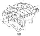
- FIG. 2 diagrammatically illustrates a typical rotary screw compressor.
- a female rotor 22 which typically may have six lobes, is mated with a male rotor 23 which typically may have four lobes.
- a thrust bearing is indicated at 24 and a radial bearing at 25.
- the sliding valve actuating piston is indicated at 26 and the control cylinder at 27.
- a shaft seal is indicated at 28.
- the suction port which connects with line 7 is indicated at 29 and the discharge port, which communicates with line 15, is indicated at 30.
- Oil supplied by the external pump 10 is injected along with the suctioned gas from line 7 to lubricate and seal compressor 13.
- the lobes, bearings, and gears must be lubricated and sealed by the oil.
- the volume of oil injected must be sufficient to cool the compressor.
- the refrigerant gas and the oil will, to some extent, be mutually soluble or completely miscible dependent on the temperature and the concentration of the oil.
- At compressor temperatures and pressures when oil floods the compressor there is a maximum surface exposure of the oil to the refrigerant gas.
- a liquid oil-rich phase which is essentially oil and a refrigerant-rich gas phase which is essentially refrigerant is the result.
- the gas phase moves to the condenser along with the portion of the liquid phase which the oil separator cannot remove.
- the oil will be present in a concentration of less than 5% whereas in the compressor it will be present in far greater concentration.
- FIG. 3 a miscibility graph has been disclosed which demonstrates an unexpected solubility characteristic in the system's operative temperature ranges.
- the graph was plotted following tests which indicated what is considered to have been demonstrated by the tests.
- the upper graph line x indicates total immiscibility or insolubility above the line at various temperatures and percentages by weight of oil in the oil-refrigerant.
- the line x indicates inverse solubility in moving from a downward slope with lower concentrations of oil in the 5% range back to an upward slope at higher compressor temperatures with higher concentrations of oil.
- Line y plots a lower temperature immiscibility or insolubility of the refrigerant in the oil at other weight concentrations and temperatures below the compressor operating temperatures, but not at concentrations below 5%.
- Both the lines x and y demonstrate a soluble zone or zone of complete miscibility where a single phase of liquid, i.e. oil in the refrigerant, is encountered from evaporator discharge temperatures of minus 62.2° C. to plus 20° C at concentrations of oil around 5%.
- a single phase of liquid i.e. oil in the refrigerant
- the oil-rich phase and the refrigerant-rich phase form essentially two discrete layers which are insoluble in this two phase zone.
- the oil-rich layer because of this, is more efficiently separated from the gas at the high temperature and pressure conditions of oil separator 14.
- the oil will effectively resist dissolution of the refrigerant-rich component in the compressor at temperatures within the range 30°-93° C., and above. It is believed the concentration of the oil in the one phase will be in the range of about 100-60% while the concentration of oil in the other phase will be in the range of about 0-20%.
- the dissolved oil can have a good return from the evaporator at the operative temperature range involved, minus 40°C. to plus 20°C., since only one phase of liquid is involved when the oil is present in the range of 20 parts per million to 5% oil.
- an oil still of well known character can be employed to tend to separate the oil from the vapor at the evaporator and return it to the compressor inlet.
- the oil can be separated at such a still and the need for an oil separator between the compressor and condenser obviated.
- a refrigerant pump injects the oil-refrigerant solution directly to the screw compressor suction, making an oil still, as such, unnecessary.
- the foregoing miscibility curves were obtained with refrigerant R-134a.
- the synthetic oil used was a 150 ISO polyoxyalkylene diol glycol having the generalized formula In this formula the integer n has a value of from 5 to 100.
- R is hydrogen or an alkyl group containing 1-4 carbon atoms. This would also include a copolymer of random distribution and block distribution. Oils of this formulation, having ISO viscosities of 100 and 150, have been tested and found to have the inverse solubility characteristics depicted in Figure 3. The lubricant was found to remain fluid at low temperatures and the time required for the refrigerant and oil to reach equilibrium was not excessive.
- oils exhibiting substantially the same inversely soluble characteristic depicted in Figure 3 are the polyoxyalkylene glycol monols of the structure where R is hydrogen or an aklyl group containing 1-4 carbon atoms, R′ is selected from the group consisting of linear or branched chain alkyl groups having 1 to about 24 carbon atoms, preferably about 4 to about 8 carbon atoms, and arylalkyl groups wherein the arylalkyl groups have about 6 to about 30 carbon atoms, preferably about 6 to about 15 carbon atoms, and contain a reactive hydrogen atom.
- the base lubricants disclosed which, however, constitute at least a majority of the complete oil.
- the complete oil will be essentially water free as usual.
- the complete oil injected will have a viscosity providing at least 4 centistokes as a sealant in the compressor and preferably 6 centistokes, while providing at least 6 centistokes and preferably 10 centistokes at the compressor bearings.
- a base oil of at least about 50 ISO will be selected.
- the operative temperature ranges normal for rotary displacement oil-flooded compressor operation, whether of the screw or vane type, are plus 30° C.
Landscapes
- Chemical & Material Sciences (AREA)
- Engineering & Computer Science (AREA)
- Chemical Kinetics & Catalysis (AREA)
- Thermal Sciences (AREA)
- Physics & Mathematics (AREA)
- Organic Chemistry (AREA)
- General Engineering & Computer Science (AREA)
- Mechanical Engineering (AREA)
- Combustion & Propulsion (AREA)
- Materials Engineering (AREA)
- General Chemical & Material Sciences (AREA)
- Oil, Petroleum & Natural Gas (AREA)
- Lubricants (AREA)
- Applications Or Details Of Rotary Compressors (AREA)
Applications Claiming Priority (2)
| Application Number | Priority Date | Filing Date | Title |
|---|---|---|---|
| US07/199,514 US4916914A (en) | 1988-05-27 | 1988-05-27 | Rotary displacement compression heat transfer systems incorporating highly fluorinated refrigerant-synthetic oil lubricant compositions |
| US199514 | 1988-05-27 |
Publications (3)
| Publication Number | Publication Date |
|---|---|
| EP0343662A2 true EP0343662A2 (de) | 1989-11-29 |
| EP0343662A3 EP0343662A3 (en) | 1990-04-18 |
| EP0343662B1 EP0343662B1 (de) | 1993-05-05 |
Family
ID=22737852
Family Applications (1)
| Application Number | Title | Priority Date | Filing Date |
|---|---|---|---|
| EP89109441A Expired - Lifetime EP0343662B1 (de) | 1988-05-27 | 1989-05-24 | Kompressionswärmeübertragungssysteme mit Rotationsverdrängung enthaltenden synthetischen hochfluorierten Kühlschmierölzusammensetzungen |
Country Status (6)
| Country | Link |
|---|---|
| US (1) | US4916914A (de) |
| EP (1) | EP0343662B1 (de) |
| JP (1) | JP2935462B2 (de) |
| AU (1) | AU616520B2 (de) |
| CA (1) | CA1307403C (de) |
| DE (1) | DE68906304T2 (de) |
Cited By (9)
| Publication number | Priority date | Publication date | Assignee | Title |
|---|---|---|---|---|
| EP0377122A1 (de) * | 1988-12-06 | 1990-07-11 | Idemitsu Kosan Company Limited | Vervendung eines specifischen Polyalkylenglykol Derivats als Schmiermittel für Kompressorkühlanlagen, Verfahren zum Schmieren und dieses Derivat enthaltende Kompressorkühlanlage |
| US5080816A (en) * | 1989-08-11 | 1992-01-14 | Nippon Oil Co., Ltd. | Lubricant for refrigerating machine |
| EP0622445A1 (de) * | 1993-04-27 | 1994-11-02 | Mitsubishi Denki Kabushiki Kaisha | Umlaufanlage für Kältemittel |
| US5531080A (en) * | 1993-04-27 | 1996-07-02 | Mitsubishi Denki Kabushiki Kaisha | Refrigerant circulating system |
| WO1997019144A1 (en) * | 1994-11-17 | 1997-05-29 | Exxon Chemical Patents Inc. | Refrigeration working fluid compositions for use in recompression type cooling systems |
| EP0846926A3 (de) * | 1993-04-27 | 1999-04-28 | Mitsubishi Denki Kabushiki Kaisha | Umlaufanlage für Kältemittel |
| WO2000043464A1 (en) * | 1999-01-25 | 2000-07-27 | The Lubrizol Corporation | Lubricant refrigerant composition for hydrofluorocarbon (hfc) refrigerants |
| US6458288B1 (en) | 1988-12-06 | 2002-10-01 | Idemitsu Kosan Co., Ltd. | Lubricating oil for refrigerator with compressor |
| CN112628963A (zh) * | 2020-12-16 | 2021-04-09 | 四川斯普信信息技术有限公司 | 双冷源热管背板多联机空调系统及运行控制的方法 |
Families Citing this family (32)
| Publication number | Priority date | Publication date | Assignee | Title |
|---|---|---|---|---|
| US5543068A (en) * | 1988-04-08 | 1996-08-06 | Japan Energy Corporation | Lubricating oils for flon compressors, compositions adapted for flon compressors and composed of mixtures of said lubricating oils and flon, and process for lubricating flon compressor by using said lubricating oils |
| US5269955A (en) * | 1989-05-08 | 1993-12-14 | Idemitsu Kosan Co., Ltd. | Lubricating oil for compression-type refrigerators and polyoxyalkylene glycol derivative |
| US4971712A (en) * | 1989-06-02 | 1990-11-20 | E. I. Du Pont De Nemours And Company | Compositions for compression refrigeration and methods of using them |
| JP2967574B2 (ja) * | 1990-11-16 | 1999-10-25 | 株式会社日立製作所 | 冷凍装置 |
| ES2104738T3 (es) * | 1991-01-17 | 1997-10-16 | Cpi Eng Services Inc | Composicion lubricante para refrigerantes fluorados. |
| JP2901369B2 (ja) * | 1991-01-30 | 1999-06-07 | 株式会社日立製作所 | 冷凍機油組成物とそれを内蔵した冷媒圧縮機及び冷凍装置 |
| US5134856A (en) * | 1991-05-21 | 1992-08-04 | Frick Company | Oil pressure maintenance for screw compressor |
| US5520833A (en) * | 1991-06-28 | 1996-05-28 | Idemitsu Kosan Co., Ltd. | Method for lubricating compression-type refrigerating cycle |
| JP3200127B2 (ja) * | 1991-12-18 | 2001-08-20 | 旭電化工業株式会社 | 冷凍機用の潤滑剤 |
| ATE195545T1 (de) | 1992-06-03 | 2000-09-15 | Henkel Corp | Schmiermittel auf basis von polyolester für kälteübertragungsmittel |
| US6183662B1 (en) | 1992-06-03 | 2001-02-06 | Henkel Corporation | Polyol ester lubricants, especially those compatible with mineral oils, for refrigerating compressors operating at high temperatures |
| US5976399A (en) | 1992-06-03 | 1999-11-02 | Henkel Corporation | Blended polyol ester lubricants for refrigerant heat transfer fluids |
| EP0594431B1 (de) * | 1992-10-23 | 1998-01-07 | Matsushita Refrigeration Company | Kältemittelkompressor und Kältesystem mit diesem Kompressor |
| US5355695A (en) * | 1992-11-30 | 1994-10-18 | Mitsubishi Denki Kabushiki Kaisha | Refrigeration device using hydrofluorocarbon refrigerant |
| BR9307842A (pt) * | 1993-03-31 | 1996-01-02 | American Standard Inc | Resfriamento de lubrificante de compressor em um sistema de refrigeração |
| US5699460A (en) * | 1993-04-27 | 1997-12-16 | Array Microsystems | Image compression coprocessor with data flow control and multiple processing units |
| US5370812A (en) * | 1993-06-28 | 1994-12-06 | Union Carbide Chemicals & Plastics Technology Corporation | Lubricant compositions for refrigerators comprising polyalkylene glycol and a hydrocarbon solvent |
| US20010019120A1 (en) | 1999-06-09 | 2001-09-06 | Nicolas E. Schnur | Method of improving performance of refrigerant systems |
| KR20020088751A (ko) * | 2001-05-21 | 2002-11-29 | 기아자동차주식회사 | 자동차 흡기장치용 연결관 |
| WO2006068664A2 (en) | 2004-07-13 | 2006-06-29 | Tiax Llc | System and method of refrigeration |
| US7780766B2 (en) * | 2006-03-27 | 2010-08-24 | Leed Fabrication Services, Inc. | Removal of vapor gas generated by an oil-containing material |
| JP4984675B2 (ja) * | 2006-06-23 | 2012-07-25 | パナソニック株式会社 | 冷媒圧縮機 |
| MX345853B (es) * | 2009-12-29 | 2017-02-17 | Arkema Inc | Metodo para seleccionar combinaciones del refrigerante y lubricante. |
| WO2012023061A1 (en) * | 2010-07-06 | 2012-02-23 | Nokia Corporation | Method and apparatus for determining mapping between a syntax element and a code word for variable length coding |
| CN102374168A (zh) * | 2010-08-10 | 2012-03-14 | 广东美芝制冷设备有限公司 | 碳氢制冷剂旋转式压缩机 |
| US9267504B2 (en) | 2010-08-30 | 2016-02-23 | Hicor Technologies, Inc. | Compressor with liquid injection cooling |
| CA2809945C (en) | 2010-08-30 | 2018-10-16 | Oscomp Systems Inc. | Compressor with liquid injection cooling |
| JP2017511860A (ja) * | 2014-02-21 | 2017-04-27 | エレクトラサーム, インコーポレーテッドElectratherm, Inc. | 容積型流体機械の潤滑装置、システムおよび方法 |
| JP6808508B2 (ja) * | 2017-01-26 | 2021-01-06 | 荏原冷熱システム株式会社 | ターボ冷凍機 |
| US10808966B2 (en) * | 2017-03-02 | 2020-10-20 | Heatcraft Refrigeration Products Llc | Cooling system with parallel compression |
| CN107353983B (zh) * | 2017-07-31 | 2020-12-08 | 广东美芝制冷设备有限公司 | 冷冻油组合物及其应用 |
| JP7253148B2 (ja) | 2020-01-24 | 2023-04-06 | いすゞ自動車株式会社 | 車両の吸気音低減構造 |
Family Cites Families (22)
| Publication number | Priority date | Publication date | Assignee | Title |
|---|---|---|---|---|
| GB1479451A (en) * | 1973-06-18 | 1977-07-13 | Svenska Rotor Maskiner Ab | Meshing screw compressors |
| US3912617A (en) * | 1974-02-14 | 1975-10-14 | Sun Oil Co Pennsylvania | Blended refrigeration oil composition |
| JPS5343278B2 (de) * | 1974-06-24 | 1978-11-17 | ||
| JPS53140469A (en) * | 1977-05-13 | 1978-12-07 | Nippon Oil Co Ltd | Component of high viscosity refrigerator oil |
| US4155865A (en) * | 1977-12-27 | 1979-05-22 | Allied Chemical Corporation | Constant boiling mixtures of 1,1,2,2-tetrafluoroethane and 1,1,1,2-tetrafluorochloroethane |
| JPS5558298A (en) * | 1978-10-25 | 1980-04-30 | Nippon Oil Co Ltd | Lubricating oil for rotary refrigerant compressor |
| US4359394A (en) * | 1978-10-30 | 1982-11-16 | Thermo King Corporation | Thermally stable lubricants for refrigerator systems |
| US4302343A (en) * | 1979-04-02 | 1981-11-24 | The Dow Chemical Company | Rotary screw compressor lubricants |
| JPS5679175A (en) * | 1979-11-30 | 1981-06-29 | Daikin Ind Ltd | Absorption refrigerant carrier composition |
| JPS5710694A (en) * | 1980-06-11 | 1982-01-20 | Mitsubishi Oil Co Ltd | Oil composition for refrigerator |
| JPS57124664A (en) * | 1981-01-28 | 1982-08-03 | Hitachi Ltd | Absorbing liquid for absorption type refrigerating machine |
| DE3265173D1 (en) * | 1981-04-07 | 1985-09-12 | Matsushita Electric Industrial Co Ltd | Composition for absorption refrigeration |
| US4455129A (en) * | 1981-05-19 | 1984-06-19 | Daikin Kogyo Co., Ltd. | Multi-vane type compressor |
| US4497721A (en) * | 1982-11-17 | 1985-02-05 | Idemitsu Kosan Company Limited | Refrigerator oil composition |
| US4452712A (en) * | 1983-01-20 | 1984-06-05 | Aluminum Company Of America | Metalworking with an aqueous synthetic lubricant containing polyoxypropylene-polyoxyethylene-polyoxypropylene block copolymers |
| JPS59207991A (ja) * | 1983-05-12 | 1984-11-26 | Idemitsu Kosan Co Ltd | 冷凍機油組成物 |
| US4689964A (en) * | 1986-04-02 | 1987-09-01 | Marin-Tek, Inc. | Zero gravity (position-insensitive) low-temperature multi-component refrigerator |
| US4755316A (en) * | 1987-10-23 | 1988-07-05 | Allied-Signal Inc. | Refrigeration lubricants |
| JPH06102792B2 (ja) * | 1987-10-30 | 1994-12-14 | 出光興産株式会社 | フッ素含有アルカン冷媒用潤滑油 |
| JP2556547B2 (ja) * | 1988-04-08 | 1996-11-20 | 株式会社ジャパンエナジー | カーエアコン用フロン圧縮機用潤滑油 |
| JP2556548B2 (ja) * | 1988-04-08 | 1996-11-20 | 株式会社ジャパンエナジー | フロン圧縮機に用いる潤滑油 |
| JPH0823030B2 (ja) * | 1988-04-22 | 1996-03-06 | 日本石油株式会社 | カーエアコン用冷凍機油組成物 |
-
1988
- 1988-05-27 US US07/199,514 patent/US4916914A/en not_active Expired - Lifetime
-
1989
- 1989-05-24 DE DE8989109441T patent/DE68906304T2/de not_active Expired - Fee Related
- 1989-05-24 EP EP89109441A patent/EP0343662B1/de not_active Expired - Lifetime
- 1989-05-26 AU AU35218/89A patent/AU616520B2/en not_active Expired
- 1989-05-26 CA CA000600889A patent/CA1307403C/en not_active Expired - Lifetime
- 1989-05-26 JP JP1134485A patent/JP2935462B2/ja not_active Expired - Fee Related
Cited By (17)
| Publication number | Priority date | Publication date | Assignee | Title |
|---|---|---|---|---|
| EP0377122A1 (de) * | 1988-12-06 | 1990-07-11 | Idemitsu Kosan Company Limited | Vervendung eines specifischen Polyalkylenglykol Derivats als Schmiermittel für Kompressorkühlanlagen, Verfahren zum Schmieren und dieses Derivat enthaltende Kompressorkühlanlage |
| US7531488B2 (en) | 1988-12-06 | 2009-05-12 | Idemitsu Kosan Co., Ltd. | Lubricating oil for refrigerator with compressor |
| EP0634467A3 (de) * | 1988-12-06 | 1995-03-01 | Idemitsu Kosan Co | Schmieröl für ein Kompressor Kühlgerät. |
| US7517839B2 (en) | 1988-12-06 | 2009-04-14 | Idemitsu Kosan Co., Ltd. | Lubricating oil for refrigerator with compressor |
| US6458288B1 (en) | 1988-12-06 | 2002-10-01 | Idemitsu Kosan Co., Ltd. | Lubricating oil for refrigerator with compressor |
| US5080816A (en) * | 1989-08-11 | 1992-01-14 | Nippon Oil Co., Ltd. | Lubricant for refrigerating machine |
| EP0852323A3 (de) * | 1993-04-27 | 1999-12-15 | Mitsubishi Denki Kabushiki Kaisha | Umlaufanlage für Kältemittel |
| EP0844300A3 (de) * | 1993-04-27 | 1999-04-28 | Mitsubishi Denki Kabushiki Kaisha | Umlaufanlage für Kältemittel |
| EP0846926A3 (de) * | 1993-04-27 | 1999-04-28 | Mitsubishi Denki Kabushiki Kaisha | Umlaufanlage für Kältemittel |
| EP0846925A3 (de) * | 1993-04-27 | 1999-12-15 | Mitsubishi Denki Kabushiki Kaisha | Umlaufanlage für Kältemittel |
| EP0846751A3 (de) * | 1993-04-27 | 1999-12-22 | Mitsubishi Denki Kabushiki Kaisha | Umlaufanlage für Kältemittel |
| US5531080A (en) * | 1993-04-27 | 1996-07-02 | Mitsubishi Denki Kabushiki Kaisha | Refrigerant circulating system |
| EP0622445A1 (de) * | 1993-04-27 | 1994-11-02 | Mitsubishi Denki Kabushiki Kaisha | Umlaufanlage für Kältemittel |
| WO1997019144A1 (en) * | 1994-11-17 | 1997-05-29 | Exxon Chemical Patents Inc. | Refrigeration working fluid compositions for use in recompression type cooling systems |
| WO2000043464A1 (en) * | 1999-01-25 | 2000-07-27 | The Lubrizol Corporation | Lubricant refrigerant composition for hydrofluorocarbon (hfc) refrigerants |
| US6374629B1 (en) | 1999-01-25 | 2002-04-23 | The Lubrizol Corporation | Lubricant refrigerant composition for hydrofluorocarbon (HFC) refrigerants |
| CN112628963A (zh) * | 2020-12-16 | 2021-04-09 | 四川斯普信信息技术有限公司 | 双冷源热管背板多联机空调系统及运行控制的方法 |
Also Published As
| Publication number | Publication date |
|---|---|
| US4916914A (en) | 1990-04-17 |
| AU616520B2 (en) | 1991-10-31 |
| AU3521889A (en) | 1989-11-30 |
| JPH0237256A (ja) | 1990-02-07 |
| DE68906304T2 (de) | 1993-08-12 |
| JP2935462B2 (ja) | 1999-08-16 |
| DE68906304D1 (de) | 1993-06-09 |
| EP0343662B1 (de) | 1993-05-05 |
| EP0343662A3 (en) | 1990-04-18 |
| CA1307403C (en) | 1992-09-15 |
Similar Documents
| Publication | Publication Date | Title |
|---|---|---|
| US4916914A (en) | Rotary displacement compression heat transfer systems incorporating highly fluorinated refrigerant-synthetic oil lubricant compositions | |
| US5027606A (en) | Rotary displacement compression heat transfer systems incorporating highly fluorinated refrigerant-synthetic oil lubricant compositions | |
| US6189322B1 (en) | Refrigerant-circulating system, and refrigerant compressor and refrigeration cycle employing the refrigerant compressor | |
| KR0156879B1 (ko) | 밀폐형압축기 | |
| US6258293B1 (en) | Refrigeration cycle | |
| US7234310B2 (en) | Very low temperature refrigeration system having a scroll compressor with liquid injection | |
| JP3594981B2 (ja) | 2気筒回転式密閉型圧縮機 | |
| KR0145952B1 (ko) | 암모니아 냉동장치 | |
| JP5339788B2 (ja) | 圧縮機および冷凍サイクル装置 | |
| JPH07208819A (ja) | 冷媒循環システム | |
| JP4874466B2 (ja) | 密閉型圧縮機 | |
| JP4316048B2 (ja) | 冷媒循環システム | |
| JP3413916B2 (ja) | 密閉型回転式圧縮機 | |
| JP2962675B2 (ja) | 冷凍装置 | |
| JPH10195426A (ja) | 冷凍装置用作動媒体及びこの媒体を用いた冷凍装置 | |
| JPH06322386A (ja) | 冷凍機用作動媒体及びそれを用いた冷凍装置 | |
| JPS59179699A (ja) | ロ−タリ形圧縮機及びその潤滑油 | |
| Hewitt et al. | From pure fluids to zeotropic and azeotropic mixtures: The effects of refrigerant‐oil solubility on system performance | |
| JP2785185B2 (ja) | カーエアコン用冷凍機油組成物 | |
| Short | Compressors and Pumps | |
| JP3241694B2 (ja) | アンモニア冷凍装置 | |
| JP2962677B2 (ja) | 冷凍装置 | |
| JPH11256177A (ja) | 冷媒循環システム | |
| JP2982970B2 (ja) | 冷凍サイクル | |
| WO2025187298A1 (ja) | 冷凍機油および冷凍装置 |
Legal Events
| Date | Code | Title | Description |
|---|---|---|---|
| PUAI | Public reference made under article 153(3) epc to a published international application that has entered the european phase |
Free format text: ORIGINAL CODE: 0009012 |
|
| AK | Designated contracting states |
Kind code of ref document: A2 Designated state(s): DE FR GB IT SE |
|
| PUAL | Search report despatched |
Free format text: ORIGINAL CODE: 0009013 |
|
| AK | Designated contracting states |
Kind code of ref document: A3 Designated state(s): DE FR GB IT SE |
|
| 17P | Request for examination filed |
Effective date: 19900827 |
|
| 17Q | First examination report despatched |
Effective date: 19911204 |
|
| GRAA | (expected) grant |
Free format text: ORIGINAL CODE: 0009210 |
|
| ITF | It: translation for a ep patent filed | ||
| AK | Designated contracting states |
Kind code of ref document: B1 Designated state(s): DE FR GB IT SE |
|
| REF | Corresponds to: |
Ref document number: 68906304 Country of ref document: DE Date of ref document: 19930609 |
|
| ET | Fr: translation filed | ||
| PLBE | No opposition filed within time limit |
Free format text: ORIGINAL CODE: 0009261 |
|
| STAA | Information on the status of an ep patent application or granted ep patent |
Free format text: STATUS: NO OPPOSITION FILED WITHIN TIME LIMIT |
|
| 26N | No opposition filed | ||
| EAL | Se: european patent in force in sweden |
Ref document number: 89109441.9 |
|
| REG | Reference to a national code |
Ref country code: GB Ref legal event code: IF02 |
|
| PGFP | Annual fee paid to national office [announced via postgrant information from national office to epo] |
Ref country code: SE Payment date: 20040521 Year of fee payment: 16 |
|
| PG25 | Lapsed in a contracting state [announced via postgrant information from national office to epo] |
Ref country code: IT Free format text: LAPSE BECAUSE OF NON-PAYMENT OF DUE FEES;WARNING: LAPSES OF ITALIAN PATENTS WITH EFFECTIVE DATE BEFORE 2007 MAY HAVE OCCURRED AT ANY TIME BEFORE 2007. THE CORRECT EFFECTIVE DATE MAY BE DIFFERENT FROM THE ONE RECORDED. Effective date: 20050524 |
|
| PG25 | Lapsed in a contracting state [announced via postgrant information from national office to epo] |
Ref country code: SE Free format text: LAPSE BECAUSE OF NON-PAYMENT OF DUE FEES Effective date: 20050525 |
|
| EUG | Se: european patent has lapsed | ||
| PGFP | Annual fee paid to national office [announced via postgrant information from national office to epo] |
Ref country code: DE Payment date: 20070702 Year of fee payment: 19 |
|
| PGFP | Annual fee paid to national office [announced via postgrant information from national office to epo] |
Ref country code: GB Payment date: 20070525 Year of fee payment: 19 |
|
| PGFP | Annual fee paid to national office [announced via postgrant information from national office to epo] |
Ref country code: FR Payment date: 20070517 Year of fee payment: 19 |
|
| GBPC | Gb: european patent ceased through non-payment of renewal fee |
Effective date: 20080524 |
|
| REG | Reference to a national code |
Ref country code: FR Ref legal event code: ST Effective date: 20090119 |
|
| PG25 | Lapsed in a contracting state [announced via postgrant information from national office to epo] |
Ref country code: DE Free format text: LAPSE BECAUSE OF NON-PAYMENT OF DUE FEES Effective date: 20081202 Ref country code: FR Free format text: LAPSE BECAUSE OF NON-PAYMENT OF DUE FEES Effective date: 20080602 |
|
| PG25 | Lapsed in a contracting state [announced via postgrant information from national office to epo] |
Ref country code: GB Free format text: LAPSE BECAUSE OF NON-PAYMENT OF DUE FEES Effective date: 20080524 |