EP0343669A1 - Système à traire - Google Patents
Système à traire Download PDFInfo
- Publication number
- EP0343669A1 EP0343669A1 EP89109463A EP89109463A EP0343669A1 EP 0343669 A1 EP0343669 A1 EP 0343669A1 EP 89109463 A EP89109463 A EP 89109463A EP 89109463 A EP89109463 A EP 89109463A EP 0343669 A1 EP0343669 A1 EP 0343669A1
- Authority
- EP
- European Patent Office
- Prior art keywords
- milking system
- milking
- ventilation
- valve
- piece
- Prior art date
- Legal status (The legal status is an assumption and is not a legal conclusion. Google has not performed a legal analysis and makes no representation as to the accuracy of the status listed.)
- Withdrawn
Links
- 238000009423 ventilation Methods 0.000 claims abstract description 24
- 239000008267 milk Substances 0.000 claims description 10
- 210000004080 milk Anatomy 0.000 claims description 10
- 235000013336 milk Nutrition 0.000 claims description 10
- 239000012528 membrane Substances 0.000 claims description 5
- 230000001419 dependent effect Effects 0.000 claims 1
- 210000002445 nipple Anatomy 0.000 description 8
- 238000007789 sealing Methods 0.000 description 3
- 238000000926 separation method Methods 0.000 description 2
- 206010011409 Cross infection Diseases 0.000 description 1
- 239000011324 bead Substances 0.000 description 1
- 230000015556 catabolic process Effects 0.000 description 1
- 230000000694 effects Effects 0.000 description 1
- 239000013013 elastic material Substances 0.000 description 1
- 238000011010 flushing procedure Methods 0.000 description 1
- 230000001771 impaired effect Effects 0.000 description 1
- 239000007788 liquid Substances 0.000 description 1
- 238000000034 method Methods 0.000 description 1
- 238000000465 moulding Methods 0.000 description 1
- 230000002093 peripheral effect Effects 0.000 description 1
- 230000002265 prevention Effects 0.000 description 1
Images
Classifications
-
- A—HUMAN NECESSITIES
- A01—AGRICULTURE; FORESTRY; ANIMAL HUSBANDRY; HUNTING; TRAPPING; FISHING
- A01J—MANUFACTURE OF DAIRY PRODUCTS
- A01J5/00—Milking machines or devices
- A01J5/04—Milking machines or devices with pneumatic manipulation of teats
- A01J5/041—Milk claw
Definitions
- the invention is concerned with improvements to milking systems, in particular with the creation of a milking system which enables air-free milking and which works without the control of air, and with an improvement in a collecting piece of milking systems in which a check valve is assigned to each short milk hose in the collecting piece.
- the removal of the milking cluster can be difficult in certain cases because the check valves prevent ventilation of the short milk hoses or the teatcup liner interior and the vacuum breakdown in the teatcup liner interior that occurs due to existing leaks can be too slow.
- a controlled ventilation is assigned to each short milking hose that connects the collecting piece to the milking cup, preferably in such a way that a controllable bore is provided in the collecting piece in the area of the connecting pieces to be connected to the short milk hoses is, which extends between the atmosphere and the area located in front of the check valve, so that everyone with the short milk hose ver in the open state of this bore tied connection piece is directly connected to the atmosphere via this hole.
- the separation of the four teats guaranteed by the non-return flaps is fully maintained.
- Ventilation channels are controlled via a valve member common to all ventilation channels, which preferably consists of a plate which is guided in particular in a recess of the collecting piece with a predeterminable prestressing force, at the bottom of which all four ventilation bores end. If the valve member is seated on the floor, the ventilation holes are closed; if it is lifted by external force, the ventilation channels are open.
- the plate-shaped valve element is preferably designed at the same time as a connection element for an automatic customer, so that whenever the automatic customer comes into operation, this plate-shaped element is raised and thus the ventilation channels are opened, which means that problem-free removal of the Milking clusters is guaranteed.
- the plate-shaped valve element is preferably arranged in the corresponding recess of the collecting piece in such a way that it can be locked in particular by a rotary movement, so that the ventilation channels are permanently closed in this case. This possibility expands the possible uses of this collectible.
- the underside of the valve element can be provided with an elastic covering, so that the ventilation channels are already closed properly when this plate-shaped element lies against the bottom of the recess.
- annular seal in the bottom area of the recess or in the outside area of the valve element an annular seal can be attached so that the bottom region, in which the ventilation openings open, is closed by the annular seal with respect to the atmosphere when the sealing element lies on top.
- the ventilation channels are preferably made as short as possible, but they are always extremely easy to implement.
- check valves which are preferably designed as flap valves, and thus the prevention of the occurrence of cross infections is in no way impaired by the attachment of these ventilation holes.
- the sealing arrangement on the plate-shaped member can also be selected such that each ventilation bore is assigned its own small-area sealing element.
- Another very important aspect of the invention which is important both with and without the ventilation openings in the collecting piece described above, is that measures are taken to counteract a vacuum increase due to the teat rubber expansion or to avoid this increase and at the same time to ensure that an undesirable control of air can be avoided.
- the present invention is refrained from providing a shut-off valve in the milking cup itself, but instead the check valves in the collecting piece are used as the closing, in conjunction with an effective closing element in the milking cup area, which is a molded part corresponding to that in the patent application 36 24 478 molding described or can also be a so-called roller tube termination in the lower part of the teat rubber.
- the space between the teat or the teat cup end and the collector end is designed as an elastic space in order to be able to compensate for changes caused by the milk flow.
- This elastic space is preferably realized in that the end flaps of the check valves in the collecting piece are membrane-like and accordingly the membrane areas migrate with respect to the normal closing level of the flap valve and can thus have a space-changing effect.
- the flap valves are made of a correspondingly elastic material, but in order to ensure the stability and the clear function as a check valve, the peripheral regions of these flap valves are reinforced, in particular bead-like reinforced.
- the ventilation valve is locked in the open position and the atmosphere inlet opening is closed. In this way, when the milking cluster is upside down, it is possible to flush liquid through the bores during flushing and thus ensure that these bores are flushed.
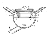
- the accompanying drawing shows in a very schematic manner a collecting piece with check valves 14 designed like a membrane, preferably all four non-return valves being combined into one component and simultaneously forming a seal 9 between the two parts of the collecting piece 2.
- the spaces between the check valves 14 and the connecting piece 3 for the short milk hoses can each be connected to the atmosphere via a ventilation hole 5. Closure and release of these ventilation holes is controlled by a plate-shaped valve element 8, which is provided with a hanger for an automatic pickup, so that when pulling a pull during the removal process, all four channels are inevitably vented.
- the plate-shaped element 8 is preferably slightly biased against the bottom surface of the recess, in which all four ventilation holes 5 open.
- a joint seal can e.g. done via an annular seal 11.
- a closable bore can be provided in the plate-shaped element 8.
Landscapes
- Life Sciences & Earth Sciences (AREA)
- Animal Husbandry (AREA)
- Environmental Sciences (AREA)
- External Artificial Organs (AREA)
- Check Valves (AREA)
Applications Claiming Priority (2)
| Application Number | Priority Date | Filing Date | Title |
|---|---|---|---|
| DE3818116 | 1988-05-27 | ||
| DE19883818116 DE3818116A1 (de) | 1988-05-27 | 1988-05-27 | Melksystem |
Publications (1)
| Publication Number | Publication Date |
|---|---|
| EP0343669A1 true EP0343669A1 (fr) | 1989-11-29 |
Family
ID=6355292
Family Applications (1)
| Application Number | Title | Priority Date | Filing Date |
|---|---|---|---|
| EP89109463A Withdrawn EP0343669A1 (fr) | 1988-05-27 | 1989-05-26 | Système à traire |
Country Status (2)
| Country | Link |
|---|---|
| EP (1) | EP0343669A1 (fr) |
| DE (1) | DE3818116A1 (fr) |
Families Citing this family (1)
| Publication number | Priority date | Publication date | Assignee | Title |
|---|---|---|---|---|
| DE102004043604A1 (de) * | 2004-09-07 | 2006-03-09 | Westfaliasurge Gmbh | Bauteil eines Melkzeugs, Melkzeug sowie Melkvorrichtung zum Melken von Tieren |
Citations (8)
| Publication number | Priority date | Publication date | Assignee | Title |
|---|---|---|---|---|
| US2702526A (en) * | 1953-05-01 | 1955-02-22 | J J Hyde | Valve device for milker claws |
| DE1482308A1 (de) * | 1963-05-03 | 1969-09-18 | Fritz Happel | Verfahren und Vorrichtung zum maschinellen Melken |
| WO1981003412A1 (fr) * | 1980-05-28 | 1981-12-10 | W Happel | Dispositif de traite |
| GB2182233A (en) * | 1985-11-02 | 1987-05-13 | Lewis Ruth Jane | Improvements in or relating to milking machines |
| US4671209A (en) * | 1985-08-26 | 1987-06-09 | Whittlestone Walter G | Teat cup claw |
| EP0246759A2 (fr) * | 1986-05-10 | 1987-11-25 | Ambic Equipment Limited | Machines à traire |
| GB2192324A (en) * | 1984-05-31 | 1988-01-13 | Nat Res Dev | Automatic milking apparatus |
| GB2192525A (en) * | 1986-07-19 | 1988-01-20 | Westfalia Separator Ag | Teat cups for mechanical milking |
-
1988
- 1988-05-27 DE DE19883818116 patent/DE3818116A1/de not_active Withdrawn
-
1989
- 1989-05-26 EP EP89109463A patent/EP0343669A1/fr not_active Withdrawn
Patent Citations (8)
| Publication number | Priority date | Publication date | Assignee | Title |
|---|---|---|---|---|
| US2702526A (en) * | 1953-05-01 | 1955-02-22 | J J Hyde | Valve device for milker claws |
| DE1482308A1 (de) * | 1963-05-03 | 1969-09-18 | Fritz Happel | Verfahren und Vorrichtung zum maschinellen Melken |
| WO1981003412A1 (fr) * | 1980-05-28 | 1981-12-10 | W Happel | Dispositif de traite |
| GB2192324A (en) * | 1984-05-31 | 1988-01-13 | Nat Res Dev | Automatic milking apparatus |
| US4671209A (en) * | 1985-08-26 | 1987-06-09 | Whittlestone Walter G | Teat cup claw |
| GB2182233A (en) * | 1985-11-02 | 1987-05-13 | Lewis Ruth Jane | Improvements in or relating to milking machines |
| EP0246759A2 (fr) * | 1986-05-10 | 1987-11-25 | Ambic Equipment Limited | Machines à traire |
| GB2192525A (en) * | 1986-07-19 | 1988-01-20 | Westfalia Separator Ag | Teat cups for mechanical milking |
Also Published As
| Publication number | Publication date |
|---|---|
| DE3818116A1 (de) | 1989-11-30 |
Similar Documents
| Publication | Publication Date | Title |
|---|---|---|
| EP3082406B1 (fr) | Vanne de sécurité | |
| DE69108970T2 (de) | Klappenventil. | |
| EP3562769A1 (fr) | Dispositif d'aspiration | |
| DE102008063715A1 (de) | Milchsammelstück mit verschließbaren Kammern | |
| DE3929182B4 (de) | Festhaltevorrichtung für eine Kraftfahrzeugtür | |
| EP0759521B1 (fr) | Clapet non-retour | |
| DE19613094A1 (de) | Magnetisches Strömungsventil | |
| DE60315559T2 (de) | Vorrichtung zum Melken eines Tieres | |
| AT396904B (de) | Vorrichtung zum entnehmen von hohlen gegenständen aus ihrer herstellform | |
| DE4334699C1 (de) | Filternder Abscheider | |
| EP0566977A1 (fr) | Soupape de fermeture pour un conduite d'aspiration | |
| EP0332090B1 (fr) | Appareil pour aspirer et évacuer un liquide contenant des matières nocives notamment de l'eau sale | |
| EP0343669A1 (fr) | Système à traire | |
| DE9101471U1 (de) | Auslaufkonus eines Behälters, z.B. eines Silos | |
| DE112016003594T5 (de) | Kanalventilbaugruppe für ein Reifendruckmanagementsystem | |
| DE2609138C2 (de) | Spülkastenablaufventil | |
| DE1960106A1 (de) | Selbstschliessendes Absperrventil zum selbsttaetigen Schliessen von Druck- oder Saugluftleitungen und dessen Steuerung | |
| DE4028182A1 (de) | Absperrvorrichtung | |
| DE919145C (de) | Automatisch wirkendes Absperrventil | |
| DE3610867A1 (de) | Verfahren und vorrichtung zum betreiben einer unterdruck-abwasseranlage | |
| DE3727661A1 (de) | Pneumatische steuervorrichtung fuer ein absperrventil an einer unterdruck-abwasserleitung | |
| EP0916775B1 (fr) | Réservoir de chasse d'eau | |
| DE2943771A1 (de) | Verfahren und vorrichtung zum ablassen von kondensat bei einer dampfdomreifenpresse | |
| DE202015001715U1 (de) | Duschabtrennung | |
| DE3022555C2 (de) | Zweiraum-Melkbecher |
Legal Events
| Date | Code | Title | Description |
|---|---|---|---|
| PUAI | Public reference made under article 153(3) epc to a published international application that has entered the european phase |
Free format text: ORIGINAL CODE: 0009012 |
|
| AK | Designated contracting states |
Kind code of ref document: A1 Designated state(s): DE FR GB |
|
| 17P | Request for examination filed |
Effective date: 19900528 |
|
| 17Q | First examination report despatched |
Effective date: 19901003 |
|
| STAA | Information on the status of an ep patent application or granted ep patent |
Free format text: STATUS: THE APPLICATION IS DEEMED TO BE WITHDRAWN |
|
| 18D | Application deemed to be withdrawn |
Effective date: 19910214 |