EP0343686A1 - Cabine pour téléphone public - Google Patents
Cabine pour téléphone public Download PDFInfo
- Publication number
- EP0343686A1 EP0343686A1 EP89109623A EP89109623A EP0343686A1 EP 0343686 A1 EP0343686 A1 EP 0343686A1 EP 89109623 A EP89109623 A EP 89109623A EP 89109623 A EP89109623 A EP 89109623A EP 0343686 A1 EP0343686 A1 EP 0343686A1
- Authority
- EP
- European Patent Office
- Prior art keywords
- panel
- housing
- panels
- telephone
- secured
- Prior art date
- Legal status (The legal status is an assumption and is not a legal conclusion. Google has not performed a legal analysis and makes no representation as to the accuracy of the status listed.)
- Withdrawn
Links
- 238000000465 moulding Methods 0.000 claims abstract description 43
- 230000003455 independent Effects 0.000 claims 1
- 238000010276 construction Methods 0.000 abstract description 7
- 239000004033 plastic Substances 0.000 description 13
- 229920003023 plastic Polymers 0.000 description 13
- 239000000463 material Substances 0.000 description 11
- 229910000831 Steel Inorganic materials 0.000 description 4
- 238000000034 method Methods 0.000 description 4
- 239000002245 particle Substances 0.000 description 4
- 239000010959 steel Substances 0.000 description 4
- 238000012423 maintenance Methods 0.000 description 3
- 230000008901 benefit Effects 0.000 description 2
- 230000002860 competitive effect Effects 0.000 description 2
- 239000003000 extruded plastic Substances 0.000 description 2
- 238000009434 installation Methods 0.000 description 2
- 235000000396 iron Nutrition 0.000 description 2
- FERIUCNNQQJTOY-UHFFFAOYSA-M Butyrate Chemical compound CCCC([O-])=O FERIUCNNQQJTOY-UHFFFAOYSA-M 0.000 description 1
- FERIUCNNQQJTOY-UHFFFAOYSA-N Butyric acid Natural products CCCC(O)=O FERIUCNNQQJTOY-UHFFFAOYSA-N 0.000 description 1
- 230000008859 change Effects 0.000 description 1
- 239000003086 colorant Substances 0.000 description 1
- 238000004891 communication Methods 0.000 description 1
- 239000002131 composite material Substances 0.000 description 1
- 230000003831 deregulation Effects 0.000 description 1
- 238000001125 extrusion Methods 0.000 description 1
- 239000000789 fastener Substances 0.000 description 1
- 239000011521 glass Substances 0.000 description 1
- 230000008569 process Effects 0.000 description 1
- 230000008439 repair process Effects 0.000 description 1
- 239000012780 transparent material Substances 0.000 description 1
- 125000000391 vinyl group Chemical group [H]C([*])=C([H])[H] 0.000 description 1
- 229920002554 vinyl polymer Polymers 0.000 description 1
- 230000000007 visual effect Effects 0.000 description 1
- 239000002023 wood Substances 0.000 description 1
Images


Classifications
-
- E—FIXED CONSTRUCTIONS
- E04—BUILDING
- E04B—GENERAL BUILDING CONSTRUCTIONS; WALLS, e.g. PARTITIONS; ROOFS; FLOORS; CEILINGS; INSULATION OR OTHER PROTECTION OF BUILDINGS
- E04B1/00—Constructions in general; Structures which are not restricted either to walls, e.g. partitions, or floors or ceilings or roofs
- E04B1/38—Connections for building structures in general
- E04B1/61—Connections for building structures in general of slab-shaped building elements with each other
- E04B1/6108—Connections for building structures in general of slab-shaped building elements with each other the frontal surfaces of the slabs connected together
- E04B1/6116—Connections for building structures in general of slab-shaped building elements with each other the frontal surfaces of the slabs connected together by locking means on lateral surfaces
-
- E—FIXED CONSTRUCTIONS
- E04—BUILDING
- E04H—BUILDINGS OR LIKE STRUCTURES FOR PARTICULAR PURPOSES; SWIMMING OR SPLASH BATHS OR POOLS; MASTS; FENCING; TENTS OR CANOPIES, IN GENERAL
- E04H1/00—Buildings or groups of buildings for dwelling or office purposes; General layout, e.g. modular co-ordination or staggered storeys
- E04H1/12—Small buildings or other erections for limited occupation, erected in the open air or arranged in buildings, e.g. kiosks, waiting shelters for bus stops or for filling stations, roofs for railway platforms, watchmen's huts or dressing cubicles
- E04H1/14—Telephone cabinets
Definitions
- the present invention relates to pay telephone housing structures. More particularly, this invention relates to housings for pay telephones that permit the display of information and advertising.
- Pay telephones facilitate the use of telephones on demand. Pay telephones may be found on streets and highways, in shopping malls, in restaurants and numerous other public establishments. Pay telephones are located in so many places that their presence is often taken for granted. Deregulation of the telephone industry has also made the service of providing pay telephones to the public a competitive business. There are currently a number of companies that place or lease pay telephones to various establishments. Typically, after arrangements have been made with the establishment owner, the pay telephone provider then installs a pay telephone at predetermined locations on the premises.
- a pay telephone may, for example, be simply mounted to a wall or post without any kind of housing or enclosure.
- a simple kind of housing may be provided around the telephone mounted to a wall or post.
- This housing may comprise partial panels to allow the caller a small measure of privacy, and/or may comprise a shelf to hold a telephone directory or provide a writing surface.
- the partial panels may protrude from the wall or post for a short distance past the front of the phone.
- One such simple housing may comprise a rectangular housing with top, bottom and side partial panels.
- the typical design of a booth comprises four walls, ceiling and perhaps a door.
- the booth itself may be mounted to a wall or post, or may stand alone.
- the telephone may be mounted along one of the walls of the booth or in one of the corners of the booth. At least a portion of one of the walls may be made of a glass or transparent material to provide visual access to the interior of the booth.
- These types of housings provide a large degree of privacy for those making the phone calls, especially if a door is provided.
- a shelf may also be provided to hold a telephone directory and to provide a writing surface.
- the typical booth requires a great deal of floor space which can limit the number of pay phone installations.
- a pay telephone housing may provide a number of different functions besides only housing a pay telephone.
- One such additional function may be an aesthetic function.
- pay telephone housings are not always considered “artworks,” it is often desirable to design furniture and other functional fixtures to be aesthetically pleasing. For example, pay telephone housings of various colors are known.
- This aesthetic function may also provide a pay telephone owner with a competitive advantage. Specifically, in a situation where a potential telephone caller must choose between one of several pay telephones, each such pay telephone owned by someone else, the potential telephone caller may be attracted to the telephone in the more attractive housing. Similarly, a potential pay telephone buyer/lessor may choose to deal with the pay telephone provider which offers the more aesthetic housings.
- a pay telephone housing may have an advertising tool.
- Examples of such housings are disclosed in U.S. Patents: Des. 263,102 and Des. 263,264.
- the housing may have specific components that are directed to advertising.
- the housing can include an electronic display positioned for viewing by the telephone callers, by passersby or both.
- An example of such a display is disclosed in the assignee's co-pending application entitled "Consumer Communication and Information System” Serial No. 199,483 filed May 27, 1988.
- the ability of the housing to function as an advertising tool may also influence the revenue generated by the pay telephone. Advertising revenue may defray the cost of the pay telephone or generate revenue which would not otherwise be derived.
- One of the disadvantages of current pay telephone enclosures is that it is difficult and expensive to change the advertising components periodically.
- Costs to the pay telephone provider can also be reduced when the design of the housing allows for quick setup and takedown. Since the pay telephone enclosures are generally set up when the least contract for the telephone begins and taken down when the lease contract for the pay telephone is ended, it is an advantage to provide a readily installable housing.
- a pay telephone housing which is made up of a plurality of panels, each panel having a predetermined width.
- the panels have predetermined widths so that a plurality of these housings may be clustered adjacent to each other in predetermined arrangements.
- a pay telephone housing which has a number of vertically arranged panels to provide a partial enclosure around the interior of the housing.
- the pay telephone is supported in the interior of the housing.
- a top panel is placed across the upper ends of the panels.
- seven panels are used for the housing.
- Each of the panels is at least 72 inches long and 11 inches wide.
- the housing can also includes a telephone bookshelf.
- the panels are connected to one another to form the housing with moldings that secure one panel to another panel.
- each panel has a groove along at least a portion of the edge being connected to the molding and the molding has a projection along at least a part of its length that fits into the grooves on the panel.
- At least one of the panels can also support an advertising placard.
- the advertising placard can be made of a translucent material and a light fixture is located within the interior of the housing and adjacent to the advertising placard.
- the housing described above can also include an electronic display mounted within the interior of the housing.
- the display can be a video monitor or a multi-line electronic display.
- an advertising placard for use with a pay telephone housing.
- a translucent panel onto which an advertisement has been incorporated is received and held by a panel holder that in turn is secured to the housing.
- the advertising panel can be either transparent or translucent.
- the translucent panel is joined to the panel holder in a registering relationship.
- the translucent panel can readily be placed into and removed from the panel holder by sliding the translucent panel into and out of the panel holder.
- a light fixture is also located within the housing opposite the side of the translucent panel and adjacent to the translucent panel.
- the light fixture may be a fluorescent lamp with a length substantially equal to the longest dimension of the placard.
- a transparent sheet can also be positioned substantially parallel to and in front of the side of the translucent panel on which the advertisement has been incorporated.
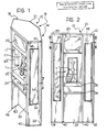
- FIGS. 1-5 there is illustrated the preferred embodiment of the invention which is a structure generally indicated at 10 for housing a pay telephone.
- Housing 10 includes a number of vertically arranged planar panels 12, 14, 16, 18 and 20 as shown in Fig. 3.
- Panel 16 may also be characterized as a back panel to housing, opposite from the front of housing 10.
- the panels preferably used in this invention have two major dimensions and one minor dimension.
- the two major dimensions correspond to the length (or height) of the panel and the horizontal width of the panel.
- the minor dimension corresponds to the thickness of the panel.
- five vertically aligned panels 12, 14, 16, 18 and 20 are provided.
- Panels 12-20 are connected together in a side-by-side arrangement to provide a partial enclosure around a telephone T.
- An interior portion, generally indicated at 11, includes a planar support member 21 secured by at least one of the panels.
- This telephone support member 21 is generally parallel to the back panel 16.
- Panels 12-20 can be made from any known materials, such as wood, particle board, plastic or any other material which may be formed into sheets.
- Housing 10 can comprise a frame, discussed below, made of steel or other rigid material for providing additional support to housing 10 and interior portion 11. For example, the frame may be attached to the floor to prevent housing 10 from being tilted over.
- an electronic information display indicated generally at 22 is also be located within the interior of housing 10.
- the display 22 can comprise a video monitor or, alternatively, a multi-line electronic display. As illustrated in FIGS. 1 and 2, the display 22 is positioned above telephone T. Display 22 can be used to provide a caller or a passerby with predetermined advertising or other information.
- Housing 10 also includes two shelves 24 and 26 located below telephone T. The space between shelves 24 and 26 form a holding area for telephone directories or the like. Further, shelf 26 includes a writing surface 28 upon which paper or the like may be supported while a caller (not shown) writes down information. Below shelf 24, a panel 30 is located and is detachable (not shown) from the rest of housing 10. Panel 30 may be removable to provide access to the electronic controls for the telephone T or monitor 22.
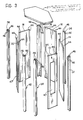
- FIG. 3 provides an exploded view of the exterior elements of housing 10 including panels 12-20 which are secured together by a number of moldings 32, 34, 36 and 38.
- the use of moldings 32-38 provides for a housing constructed with panels 12-20 without fasteners such as nuts and bolts, screws or the like. These fastenerless moldings 32-38 allow for rapid construction of the housing and easy replacement of the panels.
- Another two moldings 40 and 42 are secured to the outer vertical edges of panels 12 and 20, and preferably to frame side panels 62′ and 62 (see Fig. 8), respectively, and provide users with protection from the edges of panels 12 and 20 located on opposite sides of the opening to telephone T formed by the panels 12 and 20.
- Moldings 32-42 can be made of rubber, plastic or the like and are preferably manufactured by an extrusion process. As illustrated in FIG. 5, molding 34 ⁇ is fashioned with rounded corners on both the sides exposed to the public and the sides not exposed to the public.
- a top panel 21 is secured across the top edges of panels 12-20.
- panels 12-20 do not have the same horizontal dimension or width. Each of panels 12-20 are, however, all of substantially the same length.
- the width of panel 12 is substantially the same as panel 20, and the width of panel 14 is substantially the same as panel 18.
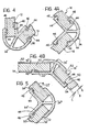
- the panels 12-20 are of a composite construction, as illustrated in FIGS. 4B and 5.
- Panels 16′ and 18′ in FIG. 4B are formed with core board 50, preferably particle board.
- the grade of particle board may be 45# Industrial Grade particle board.
- Core board 50 has a thickness B in the range of about one-fourth to three-fourths inches, preferably about one-half inch.
- a plastic layer 52 is provided on the "outside" surface of panels 16′ and 18′.
- Plastic layer 52 is made from one of several well-known plastic or plastic-like materials which are formable as sheets.
- plastic layer 52 is made of high pressure plastic, such as rigid vinyl.
- Plastic layer 52 has a thickness A, in the range of about one-hundredth to six-hundredths of an inch, preferably about three-hundredths of an inch.
- rigid paper layer 54 Opposite the side of panels 16′ and 18′ with plastic layer 52, rigid paper layer 54 is provided.
- Rigid paper layer is made from any one of several well-known paper or paper-like materials which are formable as sheets.
- Rigid paper layer 54 has a thickness C, in the range of about one-hundredth to three-hundredths of an inch, preferably about two-hundredths of an inch.
- Moldings 32, 34, 36 and 38 have predetermined angles of orientation, as seen in FIGS. 4-5. Moldings 34 and 36 form a wider angle than moldings 32 and 38 to accommodate the varying widths of the panels 12-20 to complete the partial enclosure of telephone T.
- the panels 12-20 are configured with grooves 44 along each of their outer surfaces.
- Grooves 44 can be formed either on both sides of panels 12-20 as illustrated in FIGS. 4-4A, or preferably are formed on only one side of panels 12-20, as illustrated in FIGS. 4B-5. Preferably, only one groove is provided, as in FIGS. 4B and 5.
- a closer view of a side panel 12, for example, with groove 44 is illustrated in FIG. 6.
- moldings 32-42 are provided with projections as shown at 46. Moldings 32-42 can be formed with either four projections 46 as in FIGS. 4-4A or with two projections 46 as in FIGS. 4B and 5. Projections 46 extend along at least a portion of the length of moldings 32-42.
- the grooves 44 receive projections 46.
- Moldings 32-42 are provided with either two or four projections depending on whether grooves 44 have been formed on either one side or two sides of the panels 12-20. As shown in FIGS. 4-4A, the panels 12-20 have been provided with grooves 44 on both sides and moldings 32-38 have been provided with four projections 46. In FIG. 5, the panels 12-20 are alternatively provided with one groove 44 one one side of the panels 12-20 and moldings 32-38 are alternatively provided with two projections 46.
- the depth of projections 46 should be equal or less than the depth of grooves 44.
- the panels 12-20 and moldings 32-42 provide a construction for housing 10 which may be quickly set up or taken down.
- the moldings 40 and 42 as illustrated in FIG. 3 have two grooves and two projections. Moldings 40 and 42 are used to provide user protection from the edges of panel 12 and 20 and are not used to connect one panel to another.
- a portion of the two panels 12 and 20 includes apertures 47 and 47′.
- Apertures 47 and 47′ can have a length of 41 inches.
- a pair of translucent display panels 48 and 50 shown in Figs. 1 and 2 are used to cover apertures 47 and 47′.
- Display panels 48 and 50 can be printed with a design, preferivelyably an advertising message or indication of the presence of the telephone T.
- Display panels 48 and 50 can be constructed from a variety of materials, preferivelyably a material which is capable of receiving the desired message and is aesthetically pleasing.
- Display panels 48 and 50 for example, are preferably constructed from a translucent material.
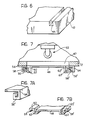
- Display panels 48 and 50 are preferably made of white translucent butyrate, having a thickness in the range of about one-twentieth to three-tenths of an inch, preferably about one-tenth of an inch. As shown in FIG.
- a light fixture 52 is secured within the housing 10 opposite the side of display panle 48 (and likewise, for middle panel 50) exposed to the public. When illuminated, light fixture 52 provides back lighting for the translucent display panels 48 and 50. In the preferred embodiment of the invention, the light fixture 52 has a length of 41 inches.
- Display panels 48 and 50 can be attached to the panels 12 and 20 in a number of ways. Display panels 48 and 50 can, for example, be screwed or glued to panels 12 and 20. However, the preferred method for securing display panels 48 and 50 is illustrated in FIGS. 7-7B. Specifically, display panel 48 is secured on both sides of its length by a pair of panel holders 54 and 54′ which are permanently attached to the panels 12 and 20. Panel holders 54 and 54′ retain the display panel 48 in a registering relationship. Panel holders 54 and 54′ include J-shaped portions 56 and 56′ which are engaged with elements 58-62′ of display panel 48. The elements 58-62′ are integral with display panel 48. The panel holders 54 and 54′ form a track which is effective to secure display panel 48.
- display panel 48 may be placed into or removed from panel holders 54 and 54′ by sliding panel 48 vertically into and out of panel holders 54 and 54′.
- This alternative means of securing provides a rapid method for replacing display panels 48 and 50. Therefore, if display panels 48 and 50 contain advertising messages, these messages may be readily changed.
- FIGS. 8 and 9 One example of an interior portion 11 construction is illustrated in FIGS. 8 and 9.
- FIG. 8 a top view of housing 10 and interior 11 along the lines 8-8 in FIG. 12 is illustrated.
- FIG. 8 varies from FIG. 2 in that monitor 22 is recessed slightly towards the back of housing 10 to illustrate telephone support member 21 and telephone T.
- Interior portion 11 comprises a frame indicated generally at 59 having four upright members 60a-60d. Uprights 60a-60d may be formed of angle irons. Uprights 60a-60d are secured together with a number of cross-bars 72 to constitute the frame 59. Cross-bars 72 can be placed in various combinations in a number of possible locations.
- Cross-bars 72 are horizontally attached between uprights 60a-60d, as illustrated in FIG. 9 or can be placed at an angle between uprights 60a-60d. As illustrated, cross-bars 72 have been attached at or near both the top and bottom of frame 59. Cross-bars 72 are attached to uprights 60a-60c in any one of several well-known ways, such as with nuts and bolts, rivets or the like.
- the telephone support member 21 is attached to the front of frame 59 by securing it to the vertical frame members 60c and 60d.
- a number of shelf support bars 66-66 ⁇ and 68-68 ⁇ provide support for shelves 26 and 24, respectively.
- Panel 30 may be removably attached to frame 59 below shelf bars 68-68 ⁇ .
- a monitor shelf 74 can be further attached between uprights 60a-60d to support monitor 22.
- Telephone T is attached to telephone support member 21 through bolts 78, or some other arrangement.
- the frame 59 is attached to the floor through the use of base supports 70 and 70′.
- the base supports 70 and 70′ are formed of angle irons which extend the width of frame 59 and for a length of the front and back, respectively, along the sides of frame 59.
- Frame 59 is attached to base supports 70 and 70′ and then the base supports 70 and 70′ are attached to the floor (not shown).
- the base supports 70 and 70′ are attached to the floor with bolts extending through apertures 80 configured in the supports 70 and 70′.
- Frame side panels 62 and 62′ are also attached to frame 59, as illustrated in FIGS. 1, 8 and 9.
- Frame side panels 62 and 62′ extend generally between and are attached to uprights 60b and 60c, and uprights 60a and 60d, respectively.
- a portion of frame side panel 62 (and likewise frame side panel 62′) is exposed to the public and provides parallel surfaces adjacent to telephone T.
- Frame side panels 62 and 62′ support light fixtures 52′ and 52, respectively.
- frame side panels 62 and 62′ have small apertures 64 and 64′ over which preferably white translucent covers 76 and 76′ have been secured.
- the same material as used for display panels 48 and 50 is used.
- light fixtures 52 and 52′ provide back lighting for translucent covers 76 and 76′ to aid telephone users in viewing the telephone T.
- the telephone support member 21 includes a standard configuration of pay telephone mounting studs, indicated generally at 78.
- the support member 21 is preferably composed at a plate, preferably steel, with a thickness in the range of about five-sixteenths to twelve-sixteenths of an inch, preferably about nine-sixteenths of an inch.
- a layer of plastic (not shown) is applied on the side of support member 21 facing the public. This plastic layer is made from the same material as plastic layer 52, discussed above. This plastic layer has a thickness in the range of about one-hundredth to six-hundredths of an inch, preferably about three-hundredths of an inch.
- the arrangement shown in FIG.9 provides improved deterrence against pay telephone theft because the telephone T is mounted to steel plate 21 which in turn is securely mounted to the floor by the frame 59.
- a group of housings 10 of similar design may be positioned relative to each other in a number of different arrangements. This feature is a results from the choice of widths for panels 12 and 20.
- the ability to cluster a group of housings 10 in novel arrangements is useful since, in many situations, installations of more than one telephone is desired.
- Arrangement of a group of housings 10 as shown in FIGS. 10A-10F allows varying arrangements of housings 10 while still providing a degree of privacy to telephone callers along with providing different aesthetic appearances.
- the specific arrangements chosen is a function of the number of housings 10 to be clustered, on the space available, and the preference of the owner or lessor of the telephones.
- housing 10 has five panels 12-20 along with a front portion 91.
- housing 10 has been provided with reference numerals to illustrate panels 12-20.
- Panels 12 and 20 have the same width; for example, a width of 12 and 23/64 inches.
- Panels 14 and 18 have the same width; for example, a width of 16 and 9/64 inches.
- the back panel 16 has a width unlike the other panels; for example, a width of 14 and 15/16 inches.
- These specified lengths for panels 12-20 provide for a front 11 of housing 10 of 20 and 9/32 inches. However, these widths may be varied and still provide a housing which is in accordance with the invention.
- a pay telephone housing has been disclosed, comprising a pay telephone housing, comprising: a first panel; a second panel secured to said first panel at a substantially 90 degree angle; a back panel secured to said second panel at a substantially 135 degree angle; a third panel secured to said back panel at a substantially 135 degree angle; a fourth panel secured to said third panel at a substantially 90 degree angle; an enclosure portion located between said first panel and said fourth panel including a planar telephone support member secured within said enclosure portion generally parallel to said back panel.
- Said first panel is substantially equal in width to said fourth panel.
- Said second panel is substantially equal in width to said third panel.
- Said first and fourth panels are substantially equal in width and said second and third panels are substantially equal in width.
- a pay telephone housing comprising: a plurality of panels secured together defining a partial enclosure, two of said panels being adjacent each other and including an obtuse angle therebetween; a supporting structure located within said partial enclosure for securing a telephone; and an electronic information display device secured to the housing above said supporting structure.
- Said panels are at least 72 inches long and 11 inches wide.
- Two of said panels are secured together with a molding member that secures one panel to another panel.
- Each of said panels includes a groove configured along at least a portion of its length and wherein said molding member includes a projection along at least a portion of its length, said projection engaged with said groove.
- At least one of said panels includes means for supporting an advertising member.
- Said advertising member has a translucent characteristic and wherein the housing includes a light fixture secured within the interior of said housing and adjacent to said advertising member.
- the housing further includes a shelf secured below said telephone supporting means.
- a pay telephone housing structure comprising: a plurality of panels configured to form an outer portion of the housing; an advertisement panel into which and advertisement has been incorporated;a panel holder secured to one of said panels configured to receive and slidably engage said advertisement panel, said panel holder and advertisement panel joining together in a registering relationship; and a light fixture secured within the housing adjacent to said advertisement panel.
- Said advertisement panel includes U-shaped members on each side of said advertisement panels and said panel includes tracks for slidably engaging said U-shaped members.
- Said advertisement panel can be placed into and removed from said panel holder by entirely sliding said advertisement panel into and out of said panel holder.
- Said light fixture comprises a fluorescent lamp with a length substantially equal to the longest dimension of said advertisement panel.
- a pay telephone housing comprising: (a) at least one housing panel, said panel having a sectioned out portion; (b) an advertisement panel into which an advertisement has been incorporated; and (c) a panel holder secured to said housing panel adapted to slidably receive and hold said advertisement panel, said panel holder and advertisement panel joining together in a registering relationship.
- Said advertisement panel includes U-shaped members on each side of said advertisement panel and said panel holder includes tracks for slidably engaging said U-shaped members.
- the housing further includes a light fixture secured within said housing adjacent to said advertisement panel.
- Said light fixture comprises a fluorescent lamp with a length substantially equal to the longest dimension of said advertisement panel.
- Said tracks are members vertically aligned on said housing panel and having a J-shaped cross-section.
- a pay telephone housing comprising: a plurality of vertically oriented outer panels; and a support frame distinct from said outer panels and including at least four spaced apart, vertical frame members; a plurality of cross-bars secured to said vertical frame members effective to secure said vertical frame members in a spaced apart relationship; and a telephone support member secured to and located between two of said vertical frame members; at least partially enclosing said support frame.
- the housing additionally includes at least one base member secured to one or more of said vertical frame members.
- Said base member is adapted to be secured to a floor.
- the housing additionally includes at least one base member secured to a lower end of two of said vertical frame members and wherein said base member is adapted to be secured to a floor.
- Said telephone support member is a rectangular steel plate.
- the housing may include at least five of said outer panels secured together forming an enclosure portion with said telephone support member located in said enclosure portion.
- Said enclosure portion includes a first side panel connected to a first one of said outer panels and said support frame and a second side panel connected to a second one of said outer panels and said support frame wherein said telephone support member is located between said first and second side panels.
- a third one of said outer panels is connected to said first outer panels, a fourth one of said outer panels is connected to said third outer panel and a fifth one of said outer panels is connected to said second and said fourth outer panels.
- Said first and second side panels are connected to said first and second outer panels by a first and second molding members respectively.
- Said third outer panel is connected to said first outer panel by a third molding member and said fifth outer panel is connected to said second outer panel by a fourth molding member.
- Said first and second outer panels may include sectioned out portions and including a first and a second advertising panel disposed to said first and second outer panels respectively over said sectioned out portions.
- the housing additionally includes light generating means located adjacent to said first and to said second side panels for illuminating said first and second advertising panels.
- the housing may additionally include an electronic display secured to said support frame.
- Said electronic display is secured to said support frame above said telephone support member.
- the housing may additionally include a monitor shelf secured to said vertical frame members above said telephone support member.
- a pay telephone housing comprising: a telephone support member; and at least five vertically aligned outer panels configured to encompass said telephone support member such that the housing has a horizontal cross-section that is generally hexagonal.
- the housing includes a support frame located within the housing and secured to said telephone support member.
- the housing may additionally include a first side panel connected to said support frame and a first of said outer panels and a second side panel connected to said support frame and a second of said outer panels so as to form an enclosure portion for said telephone support member.
- Said outer panels are connected together by molding members.
- At least one of said molding members includes an outer curved portion disposed to an outer surface of an adjacent of two of said outer panels, a central portion connected to said outer curved portion and two inner leg portions connected to said central leg portions and disposed to an inner surface of said two adjacent outer panels.
- Said inner sides of said two outer panels are configured with inner grooves and said leg portions are configured with projections that are engaged with said inner grooves.
- Said outer surfaces of said two adjacent outer panels are configured with outer grooves and said outer curved portions are configured with projections that are engaged with said outer grooves.
- the housing additionally includes an electronic display secured to said support frame above said telephone support member.
- a telephone housing has also been disclosed, com strictlyprising: a telephone support member; a plurality of vertically aligned outer panels configured to encompass said telephone support member; at least one molding member adapted to secure together two of said outer panels, without requiring screws or other independent fasteners.
- Said molding member comprisies a unitary structure which includes an outer portion disposed to an outer surface of said two outer panels, a central portion interposed between said outer panels and connected at one end to said outer portion, and two legs connected to the outer end of said central portion and respectively disposed to an inner surface of each of said outer panels.
- Said inner surfaces are configured with inner grooves extending at least a portion of the vertical length of said two outer panels and wherein said leg portions include projections engaged with said inner grooves.
- Said outer surfaces are configured with outer grooves extending at least a portion of the vertical length of said outer panels and said outer portion includes projections engaged with said outer grooves.
- Said molding member is configured out of extruded plastic.
- the housing additional includes to side panels located on either side of said telephone support member and wherein one of said side members is secured to a first one of said outer panels by a first side molding and herein said second side panel is secured to a second one of said outer panels by a second side molding.
- Said side molding includes an outer portion disposed to an outer surface of said outer panel and an outer surface of said side panel, a central portion interposed between said outer panel and said side panel connected at one end to said outer portion and an inner portion disposed to an inner surface of said outer panel and an inner surface of said side panel and connected to the other end of said central portion.
- Said inner surfaces are configured with grooves extending at least a portion of the vertical length of said outer and said side panels and said inner portion includes projections engaged with said grooves.
- Said outer portion is configured with a generally convex cross-section and said inner portions configured with a generally concave cross-section.
- Said side member is configured out of extruded plastic.
Landscapes
- Engineering & Computer Science (AREA)
- Architecture (AREA)
- Civil Engineering (AREA)
- Structural Engineering (AREA)
- Physics & Mathematics (AREA)
- Electromagnetism (AREA)
- Telephone Set Structure (AREA)
- Illuminated Signs And Luminous Advertising (AREA)
Applications Claiming Priority (2)
| Application Number | Priority Date | Filing Date | Title |
|---|---|---|---|
| US07/199,484 US4918878A (en) | 1988-05-27 | 1988-05-27 | Pay telephone enclosure |
| US199484 | 1988-05-27 |
Publications (1)
| Publication Number | Publication Date |
|---|---|
| EP0343686A1 true EP0343686A1 (fr) | 1989-11-29 |
Family
ID=22737708
Family Applications (1)
| Application Number | Title | Priority Date | Filing Date |
|---|---|---|---|
| EP89109623A Withdrawn EP0343686A1 (fr) | 1988-05-27 | 1989-05-29 | Cabine pour téléphone public |
Country Status (2)
| Country | Link |
|---|---|
| US (1) | US4918878A (fr) |
| EP (1) | EP0343686A1 (fr) |
Cited By (11)
| Publication number | Priority date | Publication date | Assignee | Title |
|---|---|---|---|---|
| GB2260147A (en) * | 1991-09-13 | 1993-04-07 | Woodhouse Company | Kiosk construction |
| EP0598549A1 (fr) * | 1992-11-10 | 1994-05-25 | Wilson, Christopher Herbert Cecil | Eléments pour construction modulaire |
| ES2088757A2 (es) * | 1992-04-02 | 1996-09-01 | Landete Emilio Alvarez | Perfeccionamientos introducidos en cabinas de informacion publica, por lector informatizado de mapas. |
| BE1010205A3 (nl) * | 1996-05-02 | 1998-03-03 | Spapen Eric | Prefabconstructie en samenstellende elementen hierbij aangewend. |
| NL1007399C2 (nl) * | 1997-10-30 | 1999-05-10 | Withagen Theodorus Adrianus Joh | Samenstel voor het opbouwen van een wand en/of gebouw en werkwijze gebruikmakend daarvan. |
| EP1229184A1 (fr) * | 2001-02-02 | 2002-08-07 | Steelcase S.A. | Elément de mobilier de télécommunication |
| WO2004114665A3 (fr) * | 2003-06-16 | 2005-03-31 | Multimedia Telesys Inc | Enceinte de systeme de videoconference |
| US7786214B2 (en) | 2002-05-03 | 2010-08-31 | Sika Technology Ag | Composition of epoxy resin, epoxy adduct, urea derivative thixotropic agent and curing agent |
| US8062468B2 (en) | 2005-07-05 | 2011-11-22 | Sika Technology Ag | Low-temperature impact resistant thermosetting epoxide resin compositions with solid epoxide resins |
| US8076424B2 (en) | 2003-07-16 | 2011-12-13 | Sika Technology Ag | Heat-curable compositions comprising low-temperature impact strength modifiers |
| US9221969B2 (en) | 2002-12-17 | 2015-12-29 | Sika Technology Ag | Thermally hardenable epoxy resin composition having an improved impact resistance at low temperatures |
Families Citing this family (24)
| Publication number | Priority date | Publication date | Assignee | Title |
|---|---|---|---|---|
| US5216853A (en) * | 1990-07-12 | 1993-06-08 | Pacific Bell | Telephone enclosure |
| USD336176S (en) | 1991-09-03 | 1993-06-08 | Acoustics Development Corporation | Telephone enclosure |
| USD387877S (en) * | 1996-07-11 | 1997-12-16 | Industries Jaro Inc. | Telephone booth |
| USD412209S (en) | 1996-08-02 | 1999-07-20 | MVM Sheet Metal Fabrications Limited | Telephone kiosk |
| USD398167S (en) | 1997-02-14 | 1998-09-15 | O'reilly Lawrence Patrick | Combined telephone booth and advertising display unit |
| US5983544A (en) * | 1997-04-17 | 1999-11-16 | Fagan; Derrell | Advertising display |
| USD399973S (en) | 1997-05-05 | 1998-10-20 | O'reilly Lawrence Patrick | Combined telephone booth and advertising display unit |
| USD409761S (en) * | 1998-07-24 | 1999-05-11 | O'reilly Lawrence Patrick | Combined telephone booth and advertising display unit |
| USD466223S1 (en) | 2001-10-22 | 2002-11-26 | Kraft Foods Holdings, Inc. | Canopy front |
| USD466224S1 (en) | 2001-10-22 | 2002-11-26 | Kraft Foods Holdings, Inc. | Facade |
| US7017310B2 (en) * | 2003-03-06 | 2006-03-28 | Dietrich Industries, Inc. | Spacer bar retainers and methods for retaining spacer bars in metal wall studs |
| USD699789S1 (en) | 2009-03-17 | 2014-02-18 | Starlite Media, Llc | Pair of advertising panels affixed to the entry portion of a shopping cart corral |
| USD653709S1 (en) | 2009-03-17 | 2012-02-07 | Starlite Media, Llc | Pair of advertising panels affixed to the entry portion of a shopping cart corral |
| US8205757B2 (en) | 2009-06-24 | 2012-06-26 | Starlite Media, Llc | Shopping cart corral for displaying one or more advertisements and method of providing same |
| USD663779S1 (en) | 2010-03-16 | 2012-07-17 | Starlite Media, Llc | Pair of advertising panels affixed to the entry portion of a shopping cart corral |
| US9367859B2 (en) | 2010-03-16 | 2016-06-14 | Starlite Media, Llc | Systems and methods for near field communication enabled shopping cart corrals |
| US8984782B1 (en) | 2010-03-16 | 2015-03-24 | Starlite Media, Llc | Shopping cart corrals with at least two advertisement panels arranged in a staggered fashion and method of providing same |
| EP2453420A1 (fr) | 2010-11-10 | 2012-05-16 | Lastinski inzeniring d.o.o. | Dispositif électronique fournissant une fonctionnalité étendue de téléphone public dans un distributeur de vente de produits |
| USD695836S1 (en) | 2013-03-13 | 2013-12-17 | Starlite Media, Llc | Combined shopping cart corral with front advertising panel |
| USD695835S1 (en) | 2013-03-13 | 2013-12-17 | Starlite Media, Llc | Combined shopping cart corral with center advertising panel |
| USD695837S1 (en) | 2013-03-13 | 2013-12-17 | Starlite Media, Llc | Combined shopping cart corral with advertising panels |
| USD786975S1 (en) | 2015-02-27 | 2017-05-16 | Starlite Media, Llc | Pair of advertising panels with triangular marker for shopping cart corral |
| USD788226S1 (en) | 2015-02-27 | 2017-05-30 | Starlite Media, Llc | Pair of advertising panels with rectangular marker for shopping cart corral |
| USD786974S1 (en) | 2015-02-27 | 2017-05-16 | Starlite Media, Llc | Pair of advertising panels with rounded marker for shopping cart corral |
Citations (7)
| Publication number | Priority date | Publication date | Assignee | Title |
|---|---|---|---|---|
| US1754026A (en) * | 1928-03-10 | 1930-04-08 | Loy Walter Wayne | Building construction |
| US1857913A (en) * | 1929-02-21 | 1932-05-10 | Judelson Julius | Booth construction |
| US2769211A (en) * | 1954-04-30 | 1956-11-06 | Burgess Manning Co | Doorless telephone booth |
| US3381430A (en) * | 1965-12-27 | 1968-05-07 | Wico Corp | Panel connector |
| DE2130978A1 (de) * | 1971-06-22 | 1973-01-11 | Siemens Ag | Telefonhaeuschen |
| FR2355737A1 (fr) * | 1976-01-14 | 1978-01-20 | May Jean Pierre | Support monobloc destine a la voirie |
| DE3540792A1 (de) * | 1985-11-16 | 1987-05-21 | Diamont Optic Gmbh | Regal |
Family Cites Families (10)
| Publication number | Priority date | Publication date | Assignee | Title |
|---|---|---|---|---|
| US2280542A (en) * | 1940-05-22 | 1942-04-21 | Western Electric Co | Cabinet |
| US2337885A (en) * | 1941-06-06 | 1943-12-28 | Bell Telephone Labor Inc | Telephone booth |
| US2982593A (en) * | 1958-03-06 | 1961-05-02 | Gladwin Plastics Inc | Telephone enclosure |
| US3247332A (en) * | 1962-05-02 | 1966-04-19 | Gladwin Plastics Inc | Housing for wall mounted telephones |
| US3445969A (en) * | 1966-09-12 | 1969-05-27 | Sherron Metallic Corp | Telephone booth |
| US3543454A (en) * | 1968-08-15 | 1970-12-01 | Alex Danin | Kiosk |
| CH632863A5 (de) * | 1978-07-12 | 1982-10-29 | Autelca Ag | Ueberwachungsvorrichtung fuer den muenzenbehaelter einer kassiereinrichtung. |
| US4501099A (en) * | 1982-07-26 | 1985-02-26 | Boaz Premakaran T | Structure for a modular greenhouse and the like |
| US4754582A (en) * | 1985-08-08 | 1988-07-05 | Flour City Architectural Metals, Div. Of E. G. Smith Construction Products, Inc. | Telephone booth with advertising displays |
| US4706399A (en) * | 1986-01-24 | 1987-11-17 | Jm Industries, Inc. | Apparatus for mounting an advertising display unit for use with a public telephone |
-
1988
- 1988-05-27 US US07/199,484 patent/US4918878A/en not_active Expired - Fee Related
-
1989
- 1989-05-29 EP EP89109623A patent/EP0343686A1/fr not_active Withdrawn
Patent Citations (7)
| Publication number | Priority date | Publication date | Assignee | Title |
|---|---|---|---|---|
| US1754026A (en) * | 1928-03-10 | 1930-04-08 | Loy Walter Wayne | Building construction |
| US1857913A (en) * | 1929-02-21 | 1932-05-10 | Judelson Julius | Booth construction |
| US2769211A (en) * | 1954-04-30 | 1956-11-06 | Burgess Manning Co | Doorless telephone booth |
| US3381430A (en) * | 1965-12-27 | 1968-05-07 | Wico Corp | Panel connector |
| DE2130978A1 (de) * | 1971-06-22 | 1973-01-11 | Siemens Ag | Telefonhaeuschen |
| FR2355737A1 (fr) * | 1976-01-14 | 1978-01-20 | May Jean Pierre | Support monobloc destine a la voirie |
| DE3540792A1 (de) * | 1985-11-16 | 1987-05-21 | Diamont Optic Gmbh | Regal |
Cited By (13)
| Publication number | Priority date | Publication date | Assignee | Title |
|---|---|---|---|---|
| GB2260147A (en) * | 1991-09-13 | 1993-04-07 | Woodhouse Company | Kiosk construction |
| GB2260147B (en) * | 1991-09-13 | 1995-07-05 | Woodhouse Company | Kiosk construction |
| ES2088757A2 (es) * | 1992-04-02 | 1996-09-01 | Landete Emilio Alvarez | Perfeccionamientos introducidos en cabinas de informacion publica, por lector informatizado de mapas. |
| EP0598549A1 (fr) * | 1992-11-10 | 1994-05-25 | Wilson, Christopher Herbert Cecil | Eléments pour construction modulaire |
| BE1010205A3 (nl) * | 1996-05-02 | 1998-03-03 | Spapen Eric | Prefabconstructie en samenstellende elementen hierbij aangewend. |
| WO1999023322A1 (fr) * | 1997-10-30 | 1999-05-14 | Nicolaas Van Eck | Systeme pour la construction de murs et/ou de batiments et procede utilisant ce systeme |
| NL1007399C2 (nl) * | 1997-10-30 | 1999-05-10 | Withagen Theodorus Adrianus Joh | Samenstel voor het opbouwen van een wand en/of gebouw en werkwijze gebruikmakend daarvan. |
| EP1229184A1 (fr) * | 2001-02-02 | 2002-08-07 | Steelcase S.A. | Elément de mobilier de télécommunication |
| US7786214B2 (en) | 2002-05-03 | 2010-08-31 | Sika Technology Ag | Composition of epoxy resin, epoxy adduct, urea derivative thixotropic agent and curing agent |
| US9221969B2 (en) | 2002-12-17 | 2015-12-29 | Sika Technology Ag | Thermally hardenable epoxy resin composition having an improved impact resistance at low temperatures |
| WO2004114665A3 (fr) * | 2003-06-16 | 2005-03-31 | Multimedia Telesys Inc | Enceinte de systeme de videoconference |
| US8076424B2 (en) | 2003-07-16 | 2011-12-13 | Sika Technology Ag | Heat-curable compositions comprising low-temperature impact strength modifiers |
| US8062468B2 (en) | 2005-07-05 | 2011-11-22 | Sika Technology Ag | Low-temperature impact resistant thermosetting epoxide resin compositions with solid epoxide resins |
Also Published As
| Publication number | Publication date |
|---|---|
| US4918878A (en) | 1990-04-24 |
Similar Documents
| Publication | Publication Date | Title |
|---|---|---|
| US4918878A (en) | Pay telephone enclosure | |
| US6311441B1 (en) | Panel-based modular wall system | |
| US5172504A (en) | Front-mount grid display having trim strips and hook and loop | |
| US7883252B2 (en) | Display device | |
| US4693026A (en) | Changeable message outdoor advertising sign | |
| US20020159246A1 (en) | Illuminated display system | |
| EP0611045A2 (fr) | Assemblage pour l'extension de panneaux séparateurs | |
| US20130160337A1 (en) | Configurable large-depth panel display | |
| GB2321992A (en) | Luminant sign | |
| GB2563059A (en) | A media wall | |
| DK0954837T3 (da) | Stativ | |
| US7272902B2 (en) | Bi-directional visual display assembly | |
| US4432170A (en) | Outdoor telephone booth | |
| US5120116A (en) | Lighted display case | |
| WO1997017688A1 (fr) | Panneau d'affichage | |
| JPH0436006B2 (fr) | ||
| CA2540753C (fr) | Ensemble combine d'indication de sortie et d'eclairage d'urgence | |
| US7627969B2 (en) | Thin profile illuminated bi-directional visual display | |
| US4364616A (en) | Directory display | |
| US6742292B1 (en) | Modular sign | |
| CA1299869C (fr) | Boite a rideaux modulee d'interieur | |
| JP3011081U (ja) | 商品等の陳列棚 | |
| SE9502759L (sv) | Monteringsbord | |
| CN221671369U (zh) | 一种用于壁龛的画作展示装置 | |
| CN110565996A (zh) | 一种活动会议房 |
Legal Events
| Date | Code | Title | Description |
|---|---|---|---|
| PUAI | Public reference made under article 153(3) epc to a published international application that has entered the european phase |
Free format text: ORIGINAL CODE: 0009012 |
|
| AK | Designated contracting states |
Kind code of ref document: A1 Designated state(s): AT BE CH DE ES FR GB GR IT LI LU NL SE |
|
| 17P | Request for examination filed |
Effective date: 19900518 |
|
| 17Q | First examination report despatched |
Effective date: 19901128 |
|
| STAA | Information on the status of an ep patent application or granted ep patent |
Free format text: STATUS: THE APPLICATION IS DEEMED TO BE WITHDRAWN |
|
| 18D | Application deemed to be withdrawn |
Effective date: 19910409 |