EP0343754A1 - Système d'attache pour boîte de jonction - Google Patents
Système d'attache pour boîte de jonction Download PDFInfo
- Publication number
- EP0343754A1 EP0343754A1 EP89201331A EP89201331A EP0343754A1 EP 0343754 A1 EP0343754 A1 EP 0343754A1 EP 89201331 A EP89201331 A EP 89201331A EP 89201331 A EP89201331 A EP 89201331A EP 0343754 A1 EP0343754 A1 EP 0343754A1
- Authority
- EP
- European Patent Office
- Prior art keywords
- box
- connection
- fitting
- junction box
- attachment frame
- Prior art date
- Legal status (The legal status is an assumption and is not a legal conclusion. Google has not performed a legal analysis and makes no representation as to the accuracy of the status listed.)
- Granted
Links
- 230000004308 accommodation Effects 0.000 description 1
- 230000002349 favourable effect Effects 0.000 description 1
Images

Classifications
-
- H—ELECTRICITY
- H02—GENERATION; CONVERSION OR DISTRIBUTION OF ELECTRIC POWER
- H02G—INSTALLATION OF ELECTRIC CABLES OR LINES, OR OF COMBINED OPTICAL AND ELECTRIC CABLES OR LINES
- H02G3/00—Installations of electric cables or lines or protective tubing therefor in or on buildings, equivalent structures or vehicles
- H02G3/02—Details
- H02G3/08—Distribution boxes; Connection or junction boxes
- H02G3/18—Distribution boxes; Connection or junction boxes providing line outlets
- H02G3/185—Floor outlets and access cups
Definitions
- the invention relates to a junction box for connection to a cable duct arranged under the floor, comprising a carpet closure frame, a box shaped attachment frame connected thereto and a fitting box with terminal connecters mounted in the attachment frame.
- Such a junction box is used for connection to a cable running under the floor of for example a socket box or suchlike plug contact.
- a socket box For use an opening is arranged in the floor and the junction box is placed such that its upper side comes to lie as much as possible in one plane with the floor-covering, for example a carpet.
- Located in the junction box is an attachment frame wherein a fitting box can be placed which serves for the accommodation of for example a socket box.
- the, for example, socket boxes are mounted in the fitting box, the fitting box is subsequently placed in the attachment frame and thereafter a through-connection is made between the cable and the various terminal connecters of the socket box or boxes.
- a number of socket boxes are usually arranged in the fitting box.
- the object of the invention is to offer a solution therefor. This is achieved according to the invention by a through-connection member with terminal connecters which is connected to the fitting box and protrudes from the attachment frame, this for connection to a cable in a cable duct, and connecting elements for through-connection to the terminal connecters of the fitting box.
- the, for example, socket boxes can be mounted beforehand in the fitting box and the required mutual through-connections can be made.
- the through-connection member is also connected to the, for example, socket boxes in the fitting box, This pre-assembly can take place in the factory or workshop, that is, under favourable working conditions. At the place of use it will suffice to connect the cable to the terminal connecters of the through-connection member. Because the through-connection member is arranged outside the attachment frame no valuable space within the fitting box is lost.
- the invention does not therefore limit the maximum number of, for example, socket boxes to be arranged.
- the through-connection member is preferably detachably connected to the fitting box using for example screws.
- the connecting elements can be formed by pre-installed wiring.
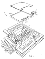
- the junction box 1 comprises a carpet closure frame 2 in addition to a box shaped attachment frame 3 connected thereto.
- a fitting box 4 can be mounted in the attachment frame 3.
- Socket box elements can be arranged in the fitting box.
- the junction box can be closed using the cover 12, which can swivel between an open and a closed position.
- the user can insert a plug into the socket box which is arranged in the fitting box 4.
- the valve is formed in two parts 14 and 15 whereby valve part 15 is pivotable relative to valve part 14. Because of the valve part 15 a downward pressing force on the connecting cord is achieved so that it does not form an obstacle in the area of use.
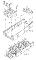
- a through-connection member 5 is arranged on the fitting box 4 for example using the screws 10, 11.
- the through-connection member displays terminal connecters 6 for the connection to the supply cable 7 which is laid in a cable duct under the floor.
- Connecting elements 9 in the form of wiring are also present for the connection with for example the socket boxes 16, 17 in the fitting box 4.
- the socket boxes 16, 17, 18 and the through-connection wiring for example 19, 20, can be pre-installed in the fitting box 4.
- the through-connection member 5 is also arranged on the fitting box 4 using the screws 10, 11 and through-connection to the fitting box 4 is provided using the wiring 9. At the place of use it is then only necessary to connect the cable to the terminal connecters 6 of the through-connection member 5.
- the box 4 is subsequently arranged in the attachment frame 3 at the required height. It is further noted that various types of connection elements, for example socket boxes and the like, are arranged to choice in the fitting box. It is also possible to place multiple fitting boxes in the attachment frame 3.
Landscapes
- Engineering & Computer Science (AREA)
- Architecture (AREA)
- Civil Engineering (AREA)
- Structural Engineering (AREA)
- Connector Housings Or Holding Contact Members (AREA)
- Connection Or Junction Boxes (AREA)
- Auxiliary Devices For And Details Of Packaging Control (AREA)
- Supplying Of Containers To The Packaging Station (AREA)
- Package Closures (AREA)
Priority Applications (1)
| Application Number | Priority Date | Filing Date | Title |
|---|---|---|---|
| AT8989201331T ATE104806T1 (de) | 1988-05-24 | 1989-05-23 | Anschlussdosenbefestigungsvorrichtung. |
Applications Claiming Priority (2)
| Application Number | Priority Date | Filing Date | Title |
|---|---|---|---|
| NL8801337 | 1988-05-24 | ||
| NL8801337A NL8801337A (nl) | 1988-05-24 | 1988-05-24 | Aansluitdoosbevestigingsinrichting. |
Publications (2)
| Publication Number | Publication Date |
|---|---|
| EP0343754A1 true EP0343754A1 (fr) | 1989-11-29 |
| EP0343754B1 EP0343754B1 (fr) | 1994-04-20 |
Family
ID=19852348
Family Applications (1)
| Application Number | Title | Priority Date | Filing Date |
|---|---|---|---|
| EP89201331A Expired - Lifetime EP0343754B1 (fr) | 1988-05-24 | 1989-05-23 | Système d'attache pour boîte de jonction |
Country Status (4)
| Country | Link |
|---|---|
| EP (1) | EP0343754B1 (fr) |
| AT (1) | ATE104806T1 (fr) |
| DE (1) | DE68914714T2 (fr) |
| NL (1) | NL8801337A (fr) |
Cited By (6)
| Publication number | Priority date | Publication date | Assignee | Title |
|---|---|---|---|---|
| GB2241389A (en) * | 1990-01-29 | 1991-08-28 | Brian John Mcdonnell | Floor box |
| GB2249880A (en) * | 1990-10-17 | 1992-05-20 | Cable Management Systems Limit | Closure device |
| GB2252681A (en) * | 1991-01-11 | 1992-08-12 | Ashley & Rock Ltd | Busbar connector |
| WO1993000732A1 (fr) * | 1991-06-20 | 1993-01-07 | Mk Electric Limited | Boitiers de prises |
| GB2450558A (en) * | 2007-06-29 | 2008-12-31 | Novar Ed & S Ltd | Service outlet floor box with depth adjustment |
| WO2011012778A2 (fr) | 2009-07-31 | 2011-02-03 | Legrand France | Boîte électrique de sol à moyens de montage rapide d'un module de connexion électrique |
Citations (2)
| Publication number | Priority date | Publication date | Assignee | Title |
|---|---|---|---|---|
| GB1402267A (en) * | 1971-09-09 | 1975-08-06 | Brown D M M | Services socket outlet device |
| US4536612A (en) * | 1983-06-03 | 1985-08-20 | Butler Manufacturing Company | Box for raised floors |
-
1988
- 1988-05-24 NL NL8801337A patent/NL8801337A/nl not_active Application Discontinuation
-
1989
- 1989-05-23 AT AT8989201331T patent/ATE104806T1/de not_active IP Right Cessation
- 1989-05-23 EP EP89201331A patent/EP0343754B1/fr not_active Expired - Lifetime
- 1989-05-23 DE DE68914714T patent/DE68914714T2/de not_active Expired - Fee Related
Patent Citations (2)
| Publication number | Priority date | Publication date | Assignee | Title |
|---|---|---|---|---|
| GB1402267A (en) * | 1971-09-09 | 1975-08-06 | Brown D M M | Services socket outlet device |
| US4536612A (en) * | 1983-06-03 | 1985-08-20 | Butler Manufacturing Company | Box for raised floors |
Cited By (9)
| Publication number | Priority date | Publication date | Assignee | Title |
|---|---|---|---|---|
| GB2241389A (en) * | 1990-01-29 | 1991-08-28 | Brian John Mcdonnell | Floor box |
| GB2249880A (en) * | 1990-10-17 | 1992-05-20 | Cable Management Systems Limit | Closure device |
| GB2249880B (en) * | 1990-10-17 | 1994-11-02 | Cable Management Systems Limit | Closure device |
| GB2252681A (en) * | 1991-01-11 | 1992-08-12 | Ashley & Rock Ltd | Busbar connector |
| WO1993000732A1 (fr) * | 1991-06-20 | 1993-01-07 | Mk Electric Limited | Boitiers de prises |
| US5571993A (en) * | 1991-06-20 | 1996-11-05 | Caradon Mk Electric Limited | Outlet boxes |
| GB2450558A (en) * | 2007-06-29 | 2008-12-31 | Novar Ed & S Ltd | Service outlet floor box with depth adjustment |
| GB2450558B (en) * | 2007-06-29 | 2011-12-28 | Novar Ed & S Ltd | Service outlet floor box with depth adjustment |
| WO2011012778A2 (fr) | 2009-07-31 | 2011-02-03 | Legrand France | Boîte électrique de sol à moyens de montage rapide d'un module de connexion électrique |
Also Published As
| Publication number | Publication date |
|---|---|
| ATE104806T1 (de) | 1994-05-15 |
| DE68914714T2 (de) | 1994-08-04 |
| NL8801337A (nl) | 1989-12-18 |
| EP0343754B1 (fr) | 1994-04-20 |
| DE68914714D1 (de) | 1994-05-26 |
Similar Documents
| Publication | Publication Date | Title |
|---|---|---|
| US6492591B1 (en) | Movable electrical and data services module | |
| US6024599A (en) | Power and communications grommet | |
| US5955701A (en) | Electrical wall outlet cover for visually impaired persons | |
| US5984719A (en) | Remote power inlet box for an auxiliary power supply system | |
| CA2030629A1 (fr) | Dispositif de securite pour aspirateur | |
| US4950178A (en) | AC power interconnect for stacked electronic devices | |
| US6254427B1 (en) | Power and communications grommet | |
| US4178468A (en) | Duct post | |
| US4627684A (en) | Housing for electrical connectors | |
| EP0343754B1 (fr) | Système d'attache pour boîte de jonction | |
| US5179252A (en) | Structure of floor junction box | |
| US5160809A (en) | Structure of wire conduit terminal assembly | |
| KR200485500Y1 (ko) | 힌지개폐구조를 갖는 덮개를 구비한 배선박스 | |
| JPH0815365B2 (ja) | フロアコンセント | |
| JPS62107626A (ja) | フリ−アクセスフロアの配線システム | |
| KR200212547Y1 (ko) | 세대통신단자함의 단자모듈 | |
| JPH0635392Y2 (ja) | コネクタ | |
| GB2176065A (en) | Underfloor cable trunking systems | |
| JPH0541132Y2 (fr) | ||
| JPS62107619A (ja) | フロアコンセント | |
| JP2000030820A (ja) | 配線器具 | |
| JPH09233645A (ja) | ジョイントボックス用取付台 | |
| JPH06165338A (ja) | 屋内配線システム | |
| WO1990007207A1 (fr) | Rallonge electrique a usages multiples | |
| JPH0550931U (ja) | 床用配線器具 |
Legal Events
| Date | Code | Title | Description |
|---|---|---|---|
| PUAI | Public reference made under article 153(3) epc to a published international application that has entered the european phase |
Free format text: ORIGINAL CODE: 0009012 |
|
| AK | Designated contracting states |
Kind code of ref document: A1 Designated state(s): AT BE CH DE ES FR GB GR IT LI LU NL SE |
|
| 17P | Request for examination filed |
Effective date: 19900109 |
|
| 17Q | First examination report despatched |
Effective date: 19920423 |
|
| GRAA | (expected) grant |
Free format text: ORIGINAL CODE: 0009210 |
|
| AK | Designated contracting states |
Kind code of ref document: B1 Designated state(s): AT BE CH DE ES FR GB GR IT LI LU NL SE |
|
| PG25 | Lapsed in a contracting state [announced via postgrant information from national office to epo] |
Ref country code: IT Free format text: LAPSE BECAUSE OF FAILURE TO SUBMIT A TRANSLATION OF THE DESCRIPTION OR TO PAY THE FEE WITHIN THE PRE;WARNING: LAPSES OF ITALIAN PATENTS WITH EFFECTIVE DATE BEFORE 2007 MAY HAVE OCCURRED AT ANY TIME BEFORE 2007. THE CORRECT EFFECTIVE DATE MAY BE DIFFERENT FROM THE ONE RECORDED.SCRIBED TIME-LIMIT Effective date: 19940420 Ref country code: GR Free format text: LAPSE BECAUSE OF FAILURE TO SUBMIT A TRANSLATION OF THE DESCRIPTION OR TO PAY THE FEE WITHIN THE PRESCRIBED TIME-LIMIT Effective date: 19940420 Ref country code: SE Free format text: THE PATENT HAS BEEN ANNULLED BY A DECISION OF A NATIONAL AUTHORITY Effective date: 19940420 Ref country code: ES Free format text: THE PATENT HAS BEEN ANNULLED BY A DECISION OF A NATIONAL AUTHORITY Effective date: 19940420 Ref country code: LI Effective date: 19940420 Ref country code: FR Effective date: 19940420 Ref country code: AT Effective date: 19940420 Ref country code: CH Effective date: 19940420 |
|
| REF | Corresponds to: |
Ref document number: 104806 Country of ref document: AT Date of ref document: 19940515 Kind code of ref document: T |
|
| REF | Corresponds to: |
Ref document number: 68914714 Country of ref document: DE Date of ref document: 19940526 |
|
| PG25 | Lapsed in a contracting state [announced via postgrant information from national office to epo] |
Ref country code: LU Free format text: LAPSE BECAUSE OF NON-PAYMENT OF DUE FEES Effective date: 19940531 |
|
| PG25 | Lapsed in a contracting state [announced via postgrant information from national office to epo] |
Ref country code: GB Effective date: 19940720 |
|
| REG | Reference to a national code |
Ref country code: CH Ref legal event code: PL |
|
| EN | Fr: translation not filed | ||
| PLBE | No opposition filed within time limit |
Free format text: ORIGINAL CODE: 0009261 |
|
| STAA | Information on the status of an ep patent application or granted ep patent |
Free format text: STATUS: NO OPPOSITION FILED WITHIN TIME LIMIT |
|
| GBPC | Gb: european patent ceased through non-payment of renewal fee |
Effective date: 19940720 |
|
| 26N | No opposition filed | ||
| PGFP | Annual fee paid to national office [announced via postgrant information from national office to epo] |
Ref country code: BE Payment date: 20040528 Year of fee payment: 16 Ref country code: DE Payment date: 20040528 Year of fee payment: 16 |
|
| PGFP | Annual fee paid to national office [announced via postgrant information from national office to epo] |
Ref country code: NL Payment date: 20040530 Year of fee payment: 16 |
|
| PG25 | Lapsed in a contracting state [announced via postgrant information from national office to epo] |
Ref country code: BE Free format text: LAPSE BECAUSE OF NON-PAYMENT OF DUE FEES Effective date: 20050531 |
|
| BERE | Be: lapsed |
Owner name: *VAN GEEL SYSTEMS B.V. Effective date: 20050531 |
|
| PG25 | Lapsed in a contracting state [announced via postgrant information from national office to epo] |
Ref country code: NL Free format text: LAPSE BECAUSE OF NON-PAYMENT OF DUE FEES Effective date: 20051201 Ref country code: DE Free format text: LAPSE BECAUSE OF NON-PAYMENT OF DUE FEES Effective date: 20051201 |
|
| NLV4 | Nl: lapsed or anulled due to non-payment of the annual fee |
Effective date: 20051201 |
|
| BERE | Be: lapsed |
Owner name: *VAN GEEL SYSTEMS B.V. Effective date: 20050531 |