EP0343888A2 - Méthode et appareil de production de pression d'un fluide et de contrôle de la couche limite - Google Patents
Méthode et appareil de production de pression d'un fluide et de contrôle de la couche limite Download PDFInfo
- Publication number
- EP0343888A2 EP0343888A2 EP89305130A EP89305130A EP0343888A2 EP 0343888 A2 EP0343888 A2 EP 0343888A2 EP 89305130 A EP89305130 A EP 89305130A EP 89305130 A EP89305130 A EP 89305130A EP 0343888 A2 EP0343888 A2 EP 0343888A2
- Authority
- EP
- European Patent Office
- Prior art keywords
- blades
- flow
- blower
- fluid
- blade
- Prior art date
- Legal status (The legal status is an assumption and is not a legal conclusion. Google has not performed a legal analysis and makes no representation as to the accuracy of the status listed.)
- Withdrawn
Links
Images










Classifications
-
- F—MECHANICAL ENGINEERING; LIGHTING; HEATING; WEAPONS; BLASTING
- F04—POSITIVE - DISPLACEMENT MACHINES FOR LIQUIDS; PUMPS FOR LIQUIDS OR ELASTIC FLUIDS
- F04D—NON-POSITIVE-DISPLACEMENT PUMPS
- F04D29/00—Details, component parts, or accessories
- F04D29/66—Combating cavitation, whirls, noise, vibration or the like; Balancing
- F04D29/68—Combating cavitation, whirls, noise, vibration or the like; Balancing by influencing boundary layers
-
- F—MECHANICAL ENGINEERING; LIGHTING; HEATING; WEAPONS; BLASTING
- F01—MACHINES OR ENGINES IN GENERAL; ENGINE PLANTS IN GENERAL; STEAM ENGINES
- F01D—NON-POSITIVE DISPLACEMENT MACHINES OR ENGINES, e.g. STEAM TURBINES
- F01D5/00—Blades; Blade-carrying members; Heating, heat-insulating, cooling or antivibration means on the blades or the members
- F01D5/12—Blades
- F01D5/14—Form or construction
- F01D5/141—Shape, i.e. outer, aerodynamic form
- F01D5/145—Means for influencing boundary layers or secondary circulations
-
- F—MECHANICAL ENGINEERING; LIGHTING; HEATING; WEAPONS; BLASTING
- F01—MACHINES OR ENGINES IN GENERAL; ENGINE PLANTS IN GENERAL; STEAM ENGINES
- F01D—NON-POSITIVE DISPLACEMENT MACHINES OR ENGINES, e.g. STEAM TURBINES
- F01D5/00—Blades; Blade-carrying members; Heating, heat-insulating, cooling or antivibration means on the blades or the members
- F01D5/12—Blades
- F01D5/14—Form or construction
- F01D5/141—Shape, i.e. outer, aerodynamic form
- F01D5/146—Shape, i.e. outer, aerodynamic form of blades with tandem configuration, split blades or slotted blades
-
- F—MECHANICAL ENGINEERING; LIGHTING; HEATING; WEAPONS; BLASTING
- F04—POSITIVE - DISPLACEMENT MACHINES FOR LIQUIDS; PUMPS FOR LIQUIDS OR ELASTIC FLUIDS
- F04D—NON-POSITIVE-DISPLACEMENT PUMPS
- F04D29/00—Details, component parts, or accessories
- F04D29/18—Rotors
-
- F—MECHANICAL ENGINEERING; LIGHTING; HEATING; WEAPONS; BLASTING
- F04—POSITIVE - DISPLACEMENT MACHINES FOR LIQUIDS; PUMPS FOR LIQUIDS OR ELASTIC FLUIDS
- F04D—NON-POSITIVE-DISPLACEMENT PUMPS
- F04D29/00—Details, component parts, or accessories
- F04D29/26—Rotors specially for elastic fluids
- F04D29/28—Rotors specially for elastic fluids for centrifugal or helico-centrifugal pumps for radial-flow or helico-centrifugal pumps
- F04D29/30—Vanes
-
- F—MECHANICAL ENGINEERING; LIGHTING; HEATING; WEAPONS; BLASTING
- F04—POSITIVE - DISPLACEMENT MACHINES FOR LIQUIDS; PUMPS FOR LIQUIDS OR ELASTIC FLUIDS
- F04D—NON-POSITIVE-DISPLACEMENT PUMPS
- F04D29/00—Details, component parts, or accessories
- F04D29/26—Rotors specially for elastic fluids
- F04D29/32—Rotors specially for elastic fluids for axial flow pumps
- F04D29/38—Blades
- F04D29/384—Blades characterised by form
-
- F—MECHANICAL ENGINEERING; LIGHTING; HEATING; WEAPONS; BLASTING
- F04—POSITIVE - DISPLACEMENT MACHINES FOR LIQUIDS; PUMPS FOR LIQUIDS OR ELASTIC FLUIDS
- F04D—NON-POSITIVE-DISPLACEMENT PUMPS
- F04D29/00—Details, component parts, or accessories
- F04D29/40—Casings; Connections of working fluid
- F04D29/42—Casings; Connections of working fluid for radial or helico-centrifugal pumps
- F04D29/44—Fluid-guiding means, e.g. diffusers
-
- F—MECHANICAL ENGINEERING; LIGHTING; HEATING; WEAPONS; BLASTING
- F04—POSITIVE - DISPLACEMENT MACHINES FOR LIQUIDS; PUMPS FOR LIQUIDS OR ELASTIC FLUIDS
- F04D—NON-POSITIVE-DISPLACEMENT PUMPS
- F04D29/00—Details, component parts, or accessories
- F04D29/40—Casings; Connections of working fluid
- F04D29/52—Casings; Connections of working fluid for axial pumps
- F04D29/54—Fluid-guiding means, e.g. diffusers
- F04D29/541—Specially adapted for elastic fluid pumps
- F04D29/542—Bladed diffusers
- F04D29/544—Blade shapes
-
- Y—GENERAL TAGGING OF NEW TECHNOLOGICAL DEVELOPMENTS; GENERAL TAGGING OF CROSS-SECTIONAL TECHNOLOGIES SPANNING OVER SEVERAL SECTIONS OF THE IPC; TECHNICAL SUBJECTS COVERED BY FORMER USPC CROSS-REFERENCE ART COLLECTIONS [XRACs] AND DIGESTS
- Y10—TECHNICAL SUBJECTS COVERED BY FORMER USPC
- Y10S—TECHNICAL SUBJECTS COVERED BY FORMER USPC CROSS-REFERENCE ART COLLECTIONS [XRACs] AND DIGESTS
- Y10S415/00—Rotary kinetic fluid motors or pumps
- Y10S415/90—Rotary blood pump
Definitions
- the apparatus is of the turbomachine type including blowers, compressors, pumps, turbines, fluid motors and the like. More particularly, it involves the use of specially designed impeller blades to deflect the flow of fluid while simultaneously maintaining the average outlet relative velocity equal to or greater than approximately 0.6 times the inlet relative velocity at the hub and tip of the impeller blade followed by generating substantial pressure in guide vanes by turning back the flow of fluid by an amount approximately equal to the amount of deflection of the fluid through the impeller blades while simultaneously decelerating the flow of fluid by maintaining the ratio of the axial through flow velocity through the fluid flow path to the outlet velocity equal to approximately 0.66 or less.
- It also relates to a method and apparatus for producing pressurized fluid at reduced noise levels. It also relates to a method and apparatus for controlling the thickness of boundary layers formed along fluid flow paths. This invention also relates to the use of appropriately selected guide vanes to increase the length of the flow path between said guide vanes. This invention also relates to the selection of blade solidity based upon the maximum deceleration required as fluid flows through said guide vanes.
- Tandem or multiple row blades are discussed in papers by Bammert, K and Staude, R., "New Features in the Design of Axial-Flow Compressors with Tandem Blades", ASME Paper No. 81-GT-113, and Wu Guochuan, Zhuang Biaonan and Guo Bingheng, "Experimental Investigation of Tandem Blade Cascades with Double Circular Arc Profiles", ASME Paper No. 85-IGT-94. These papers recite the history as well as the recent research on this subject.
- turbomachines of the pressure generating type were constructed to generate a substantial pressure within the rotating impeller blades, e.g., all centrifugal blowers and most axial flow machines.
- Prior art turbomachines developed at least approximately 50% of the pressure generated in the "rotor" or impeller blades and the remaining amount of pressure in the guide vanes. Prior art turbomachines did not use impeller blades to deflect the fluid flow essentially without generating pressure therein while simultaneously generating all or substantially all of the pressure in the guide vanes.
- Conventional axial flow blowers generate substantial pressure within the rotating impeller blades; the degree of reaction in the rotating impeller blades is high with values up to 85%.
- the high pressure generated in the rotating blades produces flow leakage losses between the tips of the blades and the adjacent housing because the rotating blades must have a gap with a stationary structure in order to rotate. This leakage imposed performance and efficiency limitations on the apparatus.
- Prior art devices did not use slotted blades to provide a flow path of extended length in which the fluid is supported between adjacent blades thereby increasing the amount of flow deceleration.
- Prior art devices did not use separate rows of blades in which the gap between rows was located in the forward part of the combined blade.
- Prior axial flow fans and centrifugal fans operated within certain specific speed lIs ranges. Prior art axial flow fans and centrifugal fans could not be operated within reduced specific speed ranges in which the turbomachine of this invention can be operated.
- Vector flow diagrams of prior art axial flow impeller blades show that the circumferential components of the relative velocities Wu1 and Wu2 are in the same direction and are opposed to the direction of the circumferential impeller velocity direction (u).
- Vector flow diagrams of prior art impeller blades did not show the flow vector of the circumferential component of relative velocity ( Wu2 ) of said impeller blades at the outlet to be in the same direction as the circumferential velocity (u).
- Prior art diffusers provided a flow path of substantial length with converging and/or diverging flow directing surfaces to assist in the recovery of static pressure from dynamic pressure.
- Prior art diffusers conventionally are of considerable length requiring extra cost to manufacture and additional space to house the diffuser.
- Prior art diffusers did not include means for removing a portion of the boundary layer from the surfaces thereof and returning same to the fluid flow path at a point upstream of the place where same had been removed.
- Prior art diffusers did not include means to remove a portion of the boundary layer and use said removed boundary layer to cool the motor of the pump or blower before it was returned to the fluid flow path.
- a blower or pump or the like of the turbomachine type having a hub member, a plurality of impeller blades mounted on the hub member for rotation, each of said blades having a hub portion, a tip portion, a rounded leading edge and relatively sharp trailing edge, said blades having a combination of camber and blade solidity wherein, during operation of said blades at the design point, the outlet relative velocity is equal to or greater than approximately 0.6 times the inlet relative velocity at the hub of the impeller, the ratio of the outlet relative velocity to the inlet relative velocity at the hub is greater than at the tip, and the angle of flow deflection within the impeller blades is equal to approximately 49.
- each of said guide vanes including a forward row and an aft row of blades, the chord of each of the blades in the aft row being greater than the chord of each of the blades in the forward row, said blades in the aft row cooperating with said blades in the forward row, to form during operation of the blower or pump, multiple rows of blades, and each of said guide vanes having a combination of camber and blade solidity wherein the direction of discharge from said impeller blades is turned by said guide vanes back to the direction of entry of said flow into said impeller blades while the absolute flow through said stationary guide vanes undergoes a substantial flow deceleration wherein the ratio of the axial through flow velocity to absolute impeller blade exit velocity from the impeller blades equals approximately 0.66 or less at the hub location; and the pressure coefficient for the blower or pump is equal to at least 1.0 or more
- blower or pump as aforedescribed in which the pressure generated by the pump or blower is constant and the axial through flow velocity is constant from the hub to the tip at the design point of the blower or pump.
- blower or pump as aforedescribed including means to reduce high inlet velocities at the inlet of the impeller blades, said means including a hub member having an inlet diameter smaller than the outlet diameter whereby the axial flow area decreases from the inlet to the exit and the absolute through flow velocity increases from the inlet to the exit of said impeller blades.
- said guide vanes include a plurality of part or half blades each of which is disposed intermediate the adjacent aft blades to form two flow channels between said adjacent aft blades wherein each flow channel row has approximately equal amounts of flow and approximately equal rates of flow diffusion therethrough.
- each part blade has the trailing edge located on the same line as the trailing edge of said aft blades, each part blade has a chord equal to approximately one-half the chord of the aft blades and each blade row has a solidity equal to approximately 1.1 ⁇ 0.6.
- blower or pump as aforedescribed in which said blower or pump includes stationary inlet guide vanes located upstream of said impeller blades, and each of the inlet guide vanes has a combination of camber and blade solidity wherein during operation of said blower or pump the circumferential component of the flow at the exit of said inlet guide vanes is turned in a direction opposite to the direction of the circumferential impeller velocity.
- each of the blades in the forward row of said stationary outlet guide vanes has a blade solidity equal to approximately 1.3 ⁇ 0.6
- each of the blades in the aft row of said guide vanes has a blade solidity equal to approximately 1.1 ⁇ 0.6.
- each of the blades in the forward row of the stationary guide vanes includes means for adjusting pressure and flow velocity through the blower or pump during operation thereof at a predetermined speed of rotation
- said means including means for mounting each of s-id forward blades for pivotal movement about a point located closely adjacent the trailing edge of each blade of said forward row, and means for pivoting each forward blade about said point thereby changing the angle of attack of the forward row of blades and changing the flow deflection of the combined forward and aft row of blades.
- said stationary guide vanes includes a third row of blades located downstream of said aft row of blades.
- a first one of said alternating fluid flow paths discharging the fluid between adjacent aft blades and a second one of said alternating fluid flow paths discharging fluid on opposite sides of one of said adjacent aft blades, the circumferential distance separating the trailing edges of the forward blades forming the first alternating fluid flow path being equal to approximately 0.9 to 1.0 times the circumferential distance separating the trailing edges of the forward blades forming the second alternating fluid flow path.
- a blower or pump or the like of the turbomachine type having a hub member, a plurality of impeller blades mounted on the hub member for rotation, each of said blades having a hub portion, a tip portion, a rounded leading edge and a relatively sharp trailing edge, said blades having a combination of camber and blade solidity wherein, during operation of said blades at the design point, the outlet relative velocity is equal to or greater than approximately 0.6 times the inlet relative velocity at the hub of the impeller, the ratio of the outlet relative velocity to the inlet relative velocity at the hub is greater than at the tip, and the angle of flow deflection within the impeller blades is equal to or more than approximately 49 .
- a plurality of stationary guide vanes mounted on the hub member, said guide vanes being located downstream from said impeller blades and through which flows the entire flow discharged by the impeller blades, each of said guide vanes having a hub portion and tip portion, each of said guide vanes having a combination of camber and blade solidity wherein the direction of discharge from said impeller blades is turned by said guide vanes back to the direction of entry of flow into said impeller blades while the absolute flow through said stationary guide vanes undergoes a substantial flow deceleration wherein the ratio of the axial through flow velocity to absolute impeller blade exit velocity from the impeller blades equals at least approximately 0.66 or less at the hub location, and the pressure coefficient for said blower or pump is equal to at least 1.0 or more.
- blower of the centrifugal turbomachine type said blower having a stationary annular member, an impeller positioned for rotation in said stationary annular member and being radially spaced therefrom by an annular fluid path which has a fluid inlet end and a fluid outlet end of larger diameter and which has a curved flow path of progressively increasing area which extends from said fluid inlet end to said fluid outlet end, a series of impeller blade rows located in said fluid flow path and being connected to said impeller and a series of guide vane rows located in said flow path and being connected to said annular stationary member, said guide vane rows being alternated with said impeller blade rows along said flow path, each of said impeller blade rows in conjunction with an adjacent one of said guide vane rows constituting one of a series of pressure generation stages in said curved portion of said flow path, each of said impeller blades having an impeller portion, an outer blade portion, a rounded leading edge and a relatively sharp trailing edge, a combination of camber and solidity wherein, during operation of said impeller
- a blower or pump or the like of the axial flow or mixed flow turbo machine type having a hub member, a plurality of impeller blades mounted on the hub member for rotation, each of said blades having a hub portion, a tip portion, a rounded leading edge and a relatively sharp trailing edge, said blades having a combination of camber and blade solidity wherein, during operation of said blades at the design point, the outlet relative velocity is equal to or greater than approximately 0.6 times the inlet relative velocity at the hub of the impeller, the ratio of the outlet relative velocity to the inlet relative velocity at the hub is-greater than at the tip, and the angle of flow deflection within the impeller blades is equal to or greater than 50" at the hub location; a plurality of stationary guide vanes mounted on the hub member, said guide vanes being located downstream from said impeller blades and through which flows the entire flow is charged by the impeller blades, each of said guide vanes having a hub portion and a tip portion, each of said guide vanes having a combination of
- a blower or pump or the like of the turbomachine type having a plurality of impeller blades mounted on an impeller for rotation, means for rotating said impeller blades, and a fluid flow path through which the fluid flows during operation of the blower or pump, said fluid flow path including surfaces for directing the flow of fluid passing through said fluid flow path, said surfaces, during operation of the blower or pump, having a boundary layer formed thereon, the improvement comprising means for removing a portion of the boundary layer from a first predetermined part of one of said flow directing surfaces located downstream of said impeller blades and returning said removed boundary layer to the fluid flow path at a second predetermined part of said flow directing surface located upstream of said first predetermined part.
- said boundary layer removal means includes means attenuating noise during operation of said blower or pump.
- the boundary layer removal means includes means for returning said removed boundary layer to the boundary layer at a second predetermined part of said flow directing surface located upstream of said first predetermined part.
- said boundary layer removal means includes means for directing the removed boundary layer through said means for rotating said impeller blades thereby cooling said means for rotating said impeller blades.
- said boundary layer removal means includes means for removing particulate matter from the portion of the boundary layer removed from said flow directing surface.
- the means for returning the removed boundary layer to the fluid flow path includes a plurality of hollow blades each of which extends into the fluid flow path.
- a method of producing pressurized fluid comprising the steps of forming a fluid flow path, generating a flow of fluid through said fluid flow path, deflecting the flow of fluid as same flows through said fluid flow path while simultaneously maintaining substantially constant relative velocity at least at one location within said fluid flow path, and generating pressure by turning back the flow of fluid by an amount approximately equal to the amount of deflection of the fluid while simultaneously decelerating the flow of fluid by maintaining the ratio of the axial through flow velocity through the fluid flow path to the outlet velocity, before the generation of said pressure, equals approximately 0.66 or less.
- a method of removing a portion of the boundary layer formed on flow directing surfaces, forming a fluid flow passage comprising the steps of forming a fluid flow path having flow directing surfaces, generating a flow of fluid through said flow path along said flow directing surfaces while simultaneously forming a boundary layer on said flow directing surfaces, and removing a portion of the boundary layer from a first part of said boundary layer formed on at least one of said flow directing surfaces and returning said portion of said boundary layer to the fluid flow path at a location upstream of said first part by simultaneously connecting said fluid passage and fluid communication with said first part in said upstream location.
- a method of producing pressurized fluid comprising the steps of forming a fluid flow path having flow directing surfaces, generating a flow of fluid through said flow path along said flow directing surfaces while simultaneously forming a boundary layer on said flow directing surfaces, deflecting the flow of fluid as same flows through said fluid flow path while simultaneously maintaining the average relative velocity following said deflection approximately equal to the relative velocity prior to said deflection at least at one location within the fluid flow path, generating pressure by turning back the flow of fluid by an amount approximately equal to the amount of deflection of the fluid while simultaneously decelerating the flow of fluid by maintaining the ratio of the axial through flow velocity through the fluid flow path to the impeller outlet velocity during the generation of said pressure equal to approximately 0.66 or less at the hub, forming a fluid flow passage, and removing a portion of the boundary layer from a first part of said boundary layer formed on at least one of said flow directing surfaces and returning said portion of said boundary layer to the fluid flow path at a second predetermined part of said flow directing surface located upstream of said first predetermined
- a method of producing pressurized fluid at reduced noise levels comprising the steps of forming a fluid flow path, generating a flow of fluid through said fluid flow path, deflecting the flow of fluid as same flows through the fluid flow path while simultaneously maintaining the average relative velocity following said deflection approximately equal to the relative velocity prior to said deflection at least at one point in the fluid flow path, and generating pressure by turning back the flow of absolute fluid velocity by an amount approximately equal to the amount of absolute velocity deflection of the fluid while simultaneously decelerating the flow of fluid.
- the present invention relates to a blower or pump or the like of the turbomachine type for generating pressurized fluid.
- the performance of this turbomachine is characterized by a much greater pressure coefficient than has heretofore been possible for comparable devices. This is accomplished through the use of a combination of special impeller blades and guide vanes constructed in accordance with this invention.
- the turbomachine of this invention uses a smaller impeller diameter resulting in a smaller casing size so that the machine is less expensive to manufacture thereby resulting in a saving in space and weight while performing at high efficiency.
- This turbomachine generates pressure using impeller blades providing large angles of flow deflection without any appreciable reaction and guide vanes which convert the dynamic pressure to static pressure.
- This turbomachine uses a low impeller tip speed together with special configurations of impeller blades and guide vanes thereby resulting in a substantial reduction of noise levels for the same amount of flow and pressure.
- This turbomachine enables the manufacture of an axial flow machine which can be operated at a higher flow coefficient than comparable axial flow machines. This is due to the use of a smaller annulus of the through flow area and a smaller impeller tip diameter than comparable axial flow machines.
- This turbomachine also provides an axial flow machine operating at a lower specific speed than is presently possible for axial flow machines; thus, this new turbomachine can be used in lieu of certain conventional mixed flow and centrifugal blowers.
- This turbomachine also provides a centrifugal blower capable of operating at a higher pressure coefficient and lower specific speed than is presently possible for existing centrifugal machines.
- this invention provides a new range of application for pumps and blowers.
- the turbomachine of this invention utilizes means for adjusting pressure and flow velocity through the machine; this is achieved by changing the angle of attack of the forward row of blades included in the guide vanes thereby changing the flow deflection of the guide vanes as a whole. Through the use of this means, the length of flow path through the guide vanes is increased which, in turn, permits greater deceleration of flow within the guide vanes without flow separation.
- the turbomachine of this invention also includes a boundary layer removal system to reduce boundary layer thickness to relatively low values.
- a turbomachine so constructed permits large increases in the value of the included angle or equivalent diffusion angle thereby reducing the length of diffusers heretofore used. In turn, this reduces the weight of the blower and the cost to manufacture same.
- the returned boundary layer flow may, in turn, also be used to cool the blower's motor before it is returned to the fluid flow path or boundary layer.
- the invention consists of a pressure generating turbomachine such as a fan, blower or pump. These machines increase fluid pressure between fluid entrance and fluid exit from the machine.
- the machines have a rotating impeller which is driven by a shaft with energy being supplied by a motor of prime mover.
- These machines include impeller blades for turning or deflecting the flow within the impeller. They may optionally include inlet guide vanes for guidance of flow into the impeller. They also include outlet guide vanes for turning the direction of the flow, and for generating pressure as the flow passes through the downstream guide vanes.
- the performance of these machines is characterized by the non-dimensional coefficients of specific speed 1/5. pressure coefficient and flow coefficient
- axial flow blowers operate at a specific range of the specific speed ( ⁇ s ) and centrifugal blowers operate at a lower range of the specific speed.
- the two ranges of specific speed are in adjoining areas and the mixed floor blowers operate in the area where the two ranges have a common border.
- axial flow blowers constructed in accordance with the principles of the present invention operate at a much lower specific speed ( ns ) because they achieve a much higher pressure coefficient than was possible with conventional blowers.
- axial flow blowers constructed according to the present invention will compete with a certain group of centrifugal blowers except, for the same specification and shaft speed, they will be much smaller, use less space and are less costly to build.
- Centrifugal blowers constructed in accordance with the principles of the present invention will operate at a lower specific speed ( l1s ) than conventional centrifugal blowers. Also, they will compete with the expensive positive displacement machines in the range of specific speed which is presently below centrifugal blowers.
- the enhanced performance of the turbomachine of this invention is based on the use of special blades in the impeller and the stationary guide vanes.
- the pressure change in the fluid that passes through the impeller blades is very small; essentially, the impeller blades are reactionless at least at one location within the impeller. This is a substantial difference from conventional pressure generating turbomachinery which generates about 50% or more of the pressure in the impeller blades. In the turbomachine of this invention, however, all or substantially all the pressure is generated in the stationary guide vanes which are located downstream of the impeller.
- the flow leaving the guide vanes can enter a diffuser if it is desireable to reduce the discharge velocity of the turbomachine.
- the flow leaving the guide vanes can enter a second or several additional impeller-guide vane blade rows to form a multistage turbomachine.
- the turbomachine can generate a predetermined value of pressure and flow volume within a smaller diameter and with a much smaller number of stages than conventional multistage machines.
- a multistage turbomachine constructed in accordance with this invention can deliver specific values of pressure and flow at higher efficiency than certain positive displacement compressors or pumps.
- turbomachines Since axial flow and centrifugal fans constructed in accordance with the principles of this invention can now operate at lower specific speeds, this means that such turbomachines are lighter in weight, smaller in diameter and can be operated at reduced rotational speeds; thus, they can be constructed at a reduced cost. In addition, such turbomachines operate at a lower noise level and reduced vibration output. Thus, not only can axial flow blowers compete in performance with conventional mixed flow and centrifugal blowers but also they can be smaller in size which, in turn, means they can be manufactured at a lower cost.
- FIGS. 1-3 show one form of a pump or blower constructed in accordance with the subject invention.
- the blower 50 shown in Figure 1 is of the axial flow type. The direction of fluid flow is from left to right as viewed in Figures 1-3, see arrow 51 in Figure 3.
- the blower 50 includes a cylindrical or tubular housing 52 having an outwardly flared intake end 54.
- a motor housing 56 is supported by at least a part of the outlet guide vanes 58.
- the guide vanes 58 comprise two rows of blades 60 and 62. Under some circumstances, it may be desireable to fabricate the forward row of blades 60 such that it can be removed and replaced by another row of blades or the same blades disposed at a different angle.
- the blower 50 also includes a rotor 64 driven by a motor 66 through a drive shaft 68 and it carries impeller blades 70, the tips of which extend to points closely adjacent the inner surface 71 of the housing 52.
- the blower 50 may, as shown, include stationary inlet guide vanes 72 mounted upstream of the impeller blades 70 on the housing 52.
- the inlet guide vanes 72 support a hub member 73, said hub member has a hemispherical cap 73a formed at the upstream end thereof.
- the blower 50 includes a conical diffuser 74 extending rearwardly or downstream of but supported by the motor housing or second hub member 56.
- the conical diffuser 74 includes means, including fluid passage 75, for removing a portion of the boundary layer from a first predetermined part 75a of the outer surface of said conical diffuser 74 and returning said removed boundary layer to the fluid flow path 76 formed through the blower at a second predetermined part 75b of said flow directing surface location upstream of said first predetermined part 75a.
- Figure 1 shows the present preferred embodiment for a blower or pump of the axial flow turbomachine type in which the guide vanes turn back the flow of fluid by more than 49° up to 70'.
- blower 50 shown in Figure 1 is somewhat diagrammatic and is illustrative of a form of possible application of the new impeller blades and guide vanes which are a part of this invention as well as the means for removing a portion of the boundary layer from a flow directing surface.
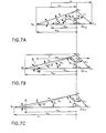
- Figures 7A-C show the vector flow diagrams for a conventional axial flow blower.
- the impeller blades reduced the entering relative velocity w 1 to the value of the exiting relative velocity W2 .
- the vectors of the circumferential component of the entering relative velocity w u1 and the exiting relative velocity w u2 are both in the direction opposing the circumferential velocity u.
- the flow channel formed between adjacent impeller blades is of increasing flow area resulting in a reduction of the relative velocity from W1 to w 2 and a corresponding increase in impeller pressure or head which is equal to H equals (w 1 2 - w 2 2 )/2g.
- the flow vector diagrams clearly identifies the velocity changes which must be accomplished by the blade configuration.
- the ratios of w 2 /w 1 , c m /c 2 and other values at the mean, hub and tip are as follows:
- the degree of reaction in the impeller is the ratio of the pressure or head generated in the impeller to the total head of the blower.
- the degree of reaction in the impeller (Si) equals H 1 /H which equals 1- ⁇ c u /2u.
- the degree of reaction in the impeller (Si) equals approximately 0.88 or 88%.
- the degree of reaction (Si) in the turbomachine of this invention is very small.
- One aspect of this invention is to provide impeller blades which generate a large deflection of flow in the impeller while simultaneously keeping changes in relative velocity between the blade entrance and exit to a minimum.
- the impeller blades of this invention perform an entirely different function from those used in prior art axial flow blowers.
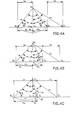
- the required performance of the impeller blades of this invention is represented in the flow diagram shown in Figures 4A-C for the case w 1 equals w 2 at the hub. As shown in Figure 4A, at the hub location the flow vector w 1 equals w z ; thus, there is neither flow acceleration or deceleration at that location.
- the impeller blade configuration for the hub as shown in Figure 4A would permit the change of flow from vector A H B H through A H C H to A H D H , the impeller relative flow would undergo a flow deceleration from A H B H to A H C H and subsequently a flow acceleration from A H C H to A H D H .
- Such a change in flow velocity is an inherently inefficient process.
- the impeller blades must be designed to induce a flow vector path from the blade entrance at A H B H in Figure 4A at the hub through location A H F H to the blade exit at A H D H , thereby creating a flow channel of essentially constant flow area and consequently constant flow velocity.
- the efficiency of the impeller is substantially improved and the boundary layer thickness is reduced thereby reducing noise generation within the blower.
- the vector of the circumferential component of the entering relative velocity w u1 is in the direction opposing the direction of the circumferential impeller velocity u while the vector of the circumferential component of the exiting relative velocity w u2 is in the same direction as the circumferential velocity u at least at one location between the hub and the tip.
- Figure 4B also shows there is a flow deceleration at the mean diameter from w 1 at A M B M to w 2 at A M D M .
- Figure 4C shows there is a flow deceleration at the tip diameter from w 1 at A T B T to w 2 at A T D T .
- the flow vector diagram of Figures 4A-C represents an axial flow machine; similar diagrams can be drawn from mixed flow and centrifugal machines demonstrating the principle of the invention.
- the inlet relative velocity is turned by the impeller blades through the angle 0 to the outlet relative velocity w 2 .
- the inlet velocity w equals the outlet flow velocity w 2 at the hub as shown in the flow vector diagram in Figure 4A. Small changes in the relative velocity from w, to W2 are within the scope of this invention and are discussed below.
- the impeller blades are of a type generating large deflection of flow:
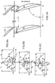
- FIGs 8A-C represent the case of using an impulse blade section at the mean impeller blade location.
- the impeller blade configuration must be designed to avoid flow velocity changes at the mean blade section from AB to AC to AD.
- the impeller blades must be designed to have a configuration such that the flow velocities follow the path AB to AF to AD.
- the flow coefficient ( ⁇ ) equals 1.0
- there is relative flow deceleration at the tip of the blade A T B T to A T D T there is relative flow deceleration at the tip of the blade A T B T to A T D T .
- the blade configuration at the tip must have flow velocities to follow the path A T B T to A T F T to A T D T and avoid A T B T to A T C T to A T D T .
- FIGS 9A-C show the flow vector diagram for a blower which has no impulse blade section within the impeller. There is flow deceleration from hub to tip and a corresponding pressure increase in the impeller. However, this type of blower has at the hub section and to a small degree at the mean section a flow vector diagram which is quite similar to the flow vector diagram of Figures 8A and 8C.
- the blade configuration at these locations must be designed to avoid large flow decelerations followed by a flow acceleration.
- the blades must have a configuration to provide a gradual increase in flow area which has a corresponding gradual decrease in flow velocity with the minimum flow velocity occurring at tne blade exit.
- the impeller flow vector diagram approaches conventional practice and the blade configuration as well as a vector diagram show a gradual change from entrance to exit.
- the flow deflection in the guide vanes is about 50° and for good performance, multiple blade guide vanes are desirable.
- this blower needs at the hub section impeller and guide vanes constructed in accordance with this invention.
- the present invention also consists of a special feature that the configuration of the impeller blades is essentially symmetric to the circumferential direction or that the deflection of relative flow is essentially symmetric to the vertical axis or through flow direction.
- the vector diagram shown in Figure 4A represents impeller blades which, at the hub, are essentially symmetric to the circumferential direction
- the flow deflection in the impeller keeps the absolute value of the relative velocity constant from the impeller blade inlet W1 to the impeller blade exit w 2 . This results in impulse type blading.
- the constant value of relative velocity w equals w 2 can be maintained only at one location, such as the hub, mean or tip of the impeller blade. At the other locations, the value of relative exit flow velocity w 2 will be accelerated or decelerated relative to the inlet velocity w, according to the free vortex principle.
- the maximum deceleration of the relative velocity from w, to W2 shall fall within the limits of equation 1 anywhere between the hub and tip of the impeller at the design point or point of maximum efficiency.
- the pressure generated by the blower is constant from hub to tip and the axial through flow velocity is constant at the design point.
- the impeller blades require a certain amount of twist from hub to tip so that the flow can enter the impeller blades without shock losses.
- impeller blades constructed in accordance with this invention may include other design modifications.
- the impeller blades having a high hub to tip ratio (v) the amount of twist in the impeller blades from the hub to tip will be small.
- the impeller blades can be designed and built to have a constant inlet and exit angle from hub to tip. In that case, the flow no longer follows the free vortex principle because there will be no twist in the blades. This features saves construction costs and the blades are easier to build.
- the maximum deceleration of the relative velocity from w1 to W2 shall fall within the limits of equation 1 anywhere between the hub and tip of the impeller at the design point or point of maximum efficiency.
- the velocity value of w, and w 2 will not be exactly constant and symmetric to the circumferential direction but wi and w 2 will approximate these conditions.
- impeller blade design consists of a blower impeller having a decreasing axial flow area from inlet to exit.
- the through flow velocity c m increases from the inlet to the exit of the impeller.
- the inlet hub diameter is substantially smaller than the exit hub diameter of the impeller and the flow through the impeller is no longer a conventional axial flow but of the mixed flow type.
- Such a design has the advantage of a different pressure-flow characteristic.
- This type of design is also used in pumps to reduce the danger of cavitation at the impeller inlet.
- the impeller blade according to this invention have, at least at one location between the impeller hub and tip, the following characteristics:
- the impeller blades essentially symmetric to the circumferential direction the following relations regarding impeller flow velocity are maintained:
- the characteristics of equation (7a) and (7b) are required at least at one location between the hub and the tip.
- the absolute value of a 1 approximately equals the absolute value of a 2 .
- blowers constructed in accordance with this invention have impeller blades of a specific configuration from hub to tip. This configuration turns the relative flow velocity within the impeller in the direction of the circumferential velocity u from blade inlet to blade exit at any location between the hub and the tip.
- Blowers constructed in accordance with this invention also have the characteristic that the pressure generation in the guide vanes is much larger than the pressure generation in the impeller:
- the above inequality exists at any location between the hub and the tip, as shown in Figures 4A-C.
- the above inequality exists at least at one location, i.e., at the hub location.
- the detailed design of the impeller blades depends substantially upon the deflection angle and the blade solidity ⁇ .
- the blade solidity is defined as the chord of the blades divided by the tangential spacing. It will be understood that the blade solidity decreases from the hub out to the tip because of the increased tangential spacing between adjacent blades. In addition, the blades must have a rounded leading edge and a reasonably sharp trailing edge to have high efficiency.
- the blade configuration must be designed to avoid flow velocity changes at the mean blade section. In order to do this, there can be a gradual decrease in flow area at the blade entrance with a corresponding gradual increase in flow area near the blade exit. It will also be understood that for an impulse blade section at the tip impeller blade location, the blade configuration must be designed to avoid flow velocity changes at the tip blade location. In order to do this, there can be a gradual decrease in flow area at the blade entrance with a corresponding gradual increase in flow area near the blade exit. Large discharge blade angles which would prevent discharge of flow from the blades must be avoided.
- the impeller flow vector diagram approaches conventional practice and the blade configuration as well as the vector diagram show a gradual change from entrance to exit.
- the flow deflection in the guide vanes is about 49°; thus, for good performance, as will be hereinafter described in greater detail, a multiple blade guide vane is desired. Accordingly, this blower needs at the hub section impeller and guide vane blades constructed in accordance with this invention.
- the pressure coefficient ( ⁇ ) for a turbomachine constructed in accordance with this invention can be increased by the appropriate use of inlet guide vanes 72, see Figure 1.
- the inlet guide vanes selected for use with the turbomachine of this invention will turn the absolute velocity c, through an angle a. in the direction opposite the impellers circumferential velocity u. It is estimated that the use of inlet guide vanes as aforesaid will substantially increase the value of the pressure coefficient ( ⁇ ) previously mentioned. This will correspondingly reduce the impeller tip speed, wherein the size of the impeller casing diameter as well as manufacturing costs will be reduced.
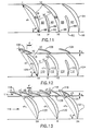
- Figure 15 is a flow vector diagram for a blower constructed in accordance with this invention which contains inlet guide vanes. As shown in Figure 15, the absolute value of the angle ⁇ 1 between the inlet velocity wi and the axial through flow velocity c m is approximately equal to the absolute value of angle a 2 between the outlet velocity W2 and the axial through flow velocity c m .
- inlet guide vanes turn the flow against the direction of the circumferential velocity u.
- the inlet guide vanes also turn the flow in opposite direction to the impeller vanes.
- exit guide vanes located downstream of the impeller blades.
- the exit guide vanes are used to turn the flow from the direction of the impeller discharge absolute velocity flow vector c 2 back to the direction of the entrance or exit velocity flow vector c, or c m through the angle ⁇ °2.
- the absolute flow undergoes a substantial flow deceleration from the values of c 2 to c m .
- Stationary guide vanes constructed in accordance with this invention include a single row of blades or two or multiple rows of blades depending upon the amount of flow deflection ⁇ - 2 and the value of flow deceleration from the flow vector C2 to the flow vector c m .
- the single row of guide vanes has a limit of flow deceleration of about 0.66 or higher values; the amount of flow deceleration is equal to the cosine of the flow angle a 2 .
- the use of two rows in the guide vanes produces a flow deceleration up to a value of about 0.28 with a range of 0.28 to 0.66; the use of three rows in the guide vanes can produce a flow deceleration of about 0.15 with a range of 0.15 to 0.28.
- the leading edge of this gap separating the two blade rows is preferably located downstream from the leading edge of "chord" for the combined blade, i.e., a line joining the leading edge of the forward blade and the trailing edge of a corresponding aft blade, e.g., see line 108 in Figure 12, by an amount equal to about one fourth of the length of said "chord".
- Chord a line joining the leading edge of the forward blade and the trailing edge of a corresponding aft blade, e.g., see line 108 in Figure 12
- Separation of the blades at this location makes the chord of the forward blade of the two rows of blade relatively short.
- chord ch 2 of the aft row of blades is always larger than the chord ch 1 of the forward rows of blades.
- the solidity of the blade system and of each of the rows of blades is the solidity of the blade system and of each of the rows of blades.
- the solidity of the blades equals the chord of the blades divided by the tangential spacing of said blades. With constant blade chord from hub to tip, the solidity of the blades at the hub is greater than the solidity at the tip because the tangential spacing at the hub is smaller than the tangential spacing at the tip.
- solidity of axial flow blower guide vanes covers a range of values. For large deflections and related large flow decelerations, the solidity of each row of blades must be considered separately.
- the aft row of blades may also include part or half blades located between adjacent aft blades. For good guidance of the flow entering the guide vanes, the solidity of the first or forward row of blades ⁇ 1, and the solidity of the second or aft row of blades a 2 as well as part blades ap shall have the following values:
- exit guide vanes built according to equations (10)-(13) inclusive and related features have the following range of characteristics:
- the number of blades 80a and 80b in the forward row (21) equals twice the number of blades 81 in the aft row (z 2 ).
- the number of blades 82 in the forward row (zi) equals the number of blades 83 in the aft row (z 2 ) for the guide vanes.
- the number of blades used in the forward row will depend, in principal part, upon the amount of guidance required for the flow passing through the guide vanes in order to avoid stalling of the flow and associated losses in efficiency.
- the flow through the guide vanes has good guidance from the line or location 1C1B to the guide vane exit 1 A-1 G.
- Figure 6 shows a two row guide vane configuration in which the number of blades in the forward row is equal to twice the number of blades in the aft row.
- Figure 5 depicts the flow vector diagram for the guide vanes of Figure 6.
- the forward blades have a different lift coefficient and different circulation than the aft blades.
- the velocity distribution is much more uniform within the forward row channels and at the discharge of the forward row blades as compared with the velocity distribution within and at the discharge of the aft row blades.
- B ⁇ 2 - 49 (18) then A is equal to or less;
- the spacing between impeller blade row and guide vane blade row is a function of the following characteristics: deflection angle; blade camber; deceleration or acceleration in the impeller blade channel; blade solidity; Reynolds number; boundary layer thickness at the impeller blade trailing edge and wake downstream of the blades.
- the impeller blades of this invention have more flow deflection within the blade channel and the blades have more camber. Both characteristics may require an increase in spacing between the impeller blades and the guide vanes when compared with conventional axial flow blower impeller blades. However, when compared to conventional axial flow blowers, the flow in the impeller flow passage has much less deceleration, perhaps zero deceleration or even acceleration.
- the blade solidity also affects the spacing between the blade rows. Low blade solidity requires relatively more spacing between the blade rows because flow discharge velocity from the row of blades has a larger variation from a mean value.
- the Reynolds number should remain approximately constant for the high performance turbomachine of this invention and the conventional blower, for the same shaft speed and flow volume, but with the high performance turbomachine generating about 50% more pressure.
- the blade spacing between impeller row and guide vanes must be increased for the high performance turbomachine of this invention in order to provide early constant fluid flow velocity at the entrance to the guide vanes. More accurate spacing values between the impeller blades and the guide vane blade rows can be determined by calculating the boundary layer thickness at the trailing edge of the impeller blades and the associated values of the wake behind the impeller blades.
- the spacing between impeller and guide vane blade rows should also be increased when there is a requirement to reduce noise levels.
- the improved noise levels are due to the improvement of the wake size and configuration but this increased spacing may result in increased fluid friction.
- Increase in solidity of the impeller blades permits a reduction in the blade spacing.
- the spacing between the forward and aft row of multiple guide vane blades is based on the same principles which have been described above with respect to the spacing between the impeller blades and the guide vanes. If the two rows of blades are located close to each other, the entire flow field must be considered.
- this configuration is satisfactory as it provides the necessary deceleration and deflection at good efficiency in a short flow path.
- the overlap of the lower surface of the trailing edge of the forward blade relative to the upper surface of the aft blade is positive.
- the axial spacing a can be zero or may have small positive or negative values.
- the forward and aft row of blades have the same number of blades. This configuration has a low solidity in the forward row of blades if their chord is shorter than the chord of the aft blades and is limited regarding the deceleration and flow deflection which can be achieved in the forward row of blades.
- each blade row an arbitrary number of blades as long as the forward row of blades has more blades than the aft row.
- the total value of the axial spacing "a" is also a function of the values of the forward row deceleration c ⁇ 2 /c 2 , forward row deflection ⁇ 2 and forward row solidity ⁇ 1 together with the total guide vane flow deceleration Cm / C2 and total flow deflection ⁇ . 2 .
- the value of this axial spacing "a” is a function of the total deceleration c m /c 2 and total deflection angle ⁇ . 2 as well as the forward row deceleration c ⁇ 2 /c 2 , forward row deflection angle ⁇ 2 and forward row solidity ⁇ 1 .
- the axial spacing a can remain relatively smaller.
- nonuniform values of discharge velocity c ⁇ 2 can be accepted at the discharge of the forward row of blades and between blades in the circumferential direction.
- each alternate forward blade 80a circumferentially with respect to the upper surface of each corresponding aft blade 81.
- this circumferential distance d is equal to or less than 0.33 times the pitch t 2 of the aft blades 83.
- the circumferential distance d is the same for each alternate forward row blade 80a.
- the amount of circumferential distance d is the same for at least one circumferential distance d between each aft blade and the lower flow surface of a corresponding forward blade.
- the number of blades used in each row of the guide vanes cannot be arbitrary.
- Blade Number Analysis Number Matrix which shows a number matrix which can be used to develop a formula and possible blade numbers for the forward row z 1 for a limited number of aft row blade numbers z 2 . Based upon this examination, if the forward row needs a blade number of at least one more than contained in the aft row, but less than twice the number of blades in the aft row, it has been found that prime numbers are not to be used for the aft row blade number z 2 : z 2 ⁇ prime number
- FIG. 11 a set of guide vanes comprising a plurality of solid blades 84. Included within the guide vanes is a plurality of part or half blades 86. By positioning each part of half blade 86 intermediate adjacent solid blades 84, flow channels 88 and 90 having approximate equal amounts of flow and approximately equal rates of flow diffusion are formed between the aft part of adjacent solid blades 84. Each part blade 86 has a chord ch 2 equal to approximately one half times the chord of the solid blades 84. Each part blade 86 has a trailing edge 92 located on approximately the same axial line 94 as the trailing edge 96 of each adjacent solid blade 84. Each part blade 86 has a solidity equal to approximately 1.1 ⁇ 0.6.
- the flow has good guidance from the line or location 1C1B to the guide vane exit at 1 A-1 G.
- the tangential spacing between adjacent solid blades 84 is reduced by one half; thus, the use of part blades 86 increases the solidity a of the flow channels 88 and 90.
- the flow is guided only by the upper surface of the solid blade 84.
- the distance 1-1 B becomes larger with guide vanes used for large deflection angles a '2 which require blades of large camber. Since the part blades 86 form channels 88 and 90 that carry equal amounts of flow and have about equal rates of flow diffusion or flow deceleration, the part blades 86 avoid flow stalling and associated losses in efficiency in the aft part of the flow channel through the solid blades 84 as shown in Figure 11.
- the guide vanes in Figure 12 include two rows of blades, a forward row 98 and aft row 100. Part blades 102 are disposed intermediate the aft part of adjacent aft blades 104. In Figure 12, the number of blades 106 in the forward row is equal to the number of blades 104 in the aft row. In accordance with formula (20) the forward row of blades 98 is axially separated from the aft row of blades 100 by an amount "a", i.e., in which ⁇ 0.12 ch 2 ⁇ a ? e.
- the solidity and chord of the part blades 102 have the same relationship to the aft blades 104 as does the solidity and the chord of the part blades 86 to the solid blades 84 shown in Figure 11.
- the circumferential distance d between the leading edge of each aft blade 104 and the trailing edge of the forward blade 106 nearest the upper surface of said aft blade 104 is equal to or less than approximately one-third times the pitch (t 2 ) of the aft blades 104.
- a line 108 which would be representative of the combined chord for an aft blade 104 and a corresponding forward blade 106.
- each aft blade 104 is located approximately one-third the length of the chord line 108 downstream of the "leading edge" of said chord line 108.
- the part blades 102 form flow channels 110 and 112 between adjacent aft blades 104.
- the flow channels 110 and 112 have similar characteristics to the flow channels 88 and 90 of Figure 11.
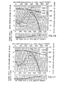
- FIG. 16 and 17 Test results made on a blower constructed in accordance with this invention are shown in Figures 16 and 17.
- a two row guide vane configuration was used in the blower.
- the blower was driven by 400 cycle electric motor operating at about 11,500 rpm.
- the blower impeller had a tip diameter of 4.9 inches and a hub diameter of 3.5 inches.
- the required flow deflection a '2 varied from 50.9 * at the hub to 45.1 at the tip.
- the aft blade used in the two row guide vane configuration in each case was NACA 651710 from the 65 series. Tests were also made for each two row guide vane configuration in which the stagger angle y of each forward blade was changed to a t 5 .. In order to reduce manufacturing costs, all guide vanes were of constant chord length and straight from hub to tip.
- the blower utilizing a plurality of single, solid blades is identified in Figures 16 and 17 as Unit 1.
- the blower using the two row guide vane configuration in which the number of blades in the forward row and the aft row are the same is shown in Figure 16 as Unit 2a and in Figure 17 as Unit 2.
- Unit 2 has the lowest solidity in the forward row, intermediate solidity in the aft row and intermediate air foil camber in both rows.
- the two row guide vane configuration (Unit 3) having twice the number of blades in the forward row as in the aft row, shows by far the best performance of all Units 1 to 3.
- Unit 3 shows the highest values of static and total pressure with essentially the same volume flow as Units 1 and 2.
- Unit 3 has the largest total blade length, the largest total blade area, intermediate solidity in the two rows of blades and the lowest cambered blade in the front row.
- Units 2a and 3a are similar to Units 2 and 3 except that the stagger angle of the front row of blades is increased by 10. for Unit 3a in Figure 16 as compared to Unit 3 in Figure 17.
- the data shown for Unit 1 in Figure 17 is the same data as shown for Unit 1 in Figure 16.
- Unit 1 has a very narrow operating range near its maximum static pressure and shows irregular pressure characteristics outside its narrow operating range.
- Unit 2 shows a greatly improved operating range compared to Unit 1 and a higher maximum static pressure.
- Unit 2 shows that the location of the maximum static pressure and of the maximum efficiency occur at an 8% larger flow as compared to Unit 2a.
- Unit 3a shows the best performance.
- Unit 3a has the largest static pressure, the largest operating range and best efficiency since its power input is identical or slightly below the power input for Unit 2a.
- Unit 3a shows improved performance compared to Units 1 and 2a over most of the flow range. Both Units 2a and 3a indicate a small decrease in flow capacity over the entire range of performance as compared to Units 1-3 as shown in Figure 17. Based upon the tests of Units 1-3, it is clear that Unit 3 is superior to Units 1 and 2 because it generates more pressure and shows improved performance over most of the pressure-flow characteristics. Also, by changing the angle of the forward blades, minor modifications in pressure-flow characteristics can be made. Unit 3 has the largest blade area of the three systems, the lowest cambered blade in the forward row and medium solidity in both rows.
- An automatic control system using adjustable guide vanes, applies to the turbomachine of this invention, including both axial and centrifugal blowers.
- the axial flow machine includes mixed flow blowers discharging into guide vanes essentially in an axial direction.
- the centrifugal blowers include mixed flow blowers discharging into vaned diffusers essentially in a radial direction.
- the performance of the axial flow blower constructed in accordance with this invention and its control are substantially different from conventional axial flow blowers.
- the difference in performance is due to the fact that the impeller blades are forwardly curved and provide a substantial flow deflection within the impeller blades.
- the axial flow blower of this invention is able to provide substantial performance changes by adjusting the impeller blades. A small rotation of the impeller blades will substantially increase or decrease the generated pressure.
- the axial flow blower of this invention has within the impeller blades essentially constant pressure. In designing an axial flow blower of this invention, the flow field is selected and the flow velocity is maintained substantially constant or with small amounts of flow acceleration or deceleration in part of the impeller blades.
- the impeller blades can be turned over a certain range and the flow will not stall since the impeller blades can operate over a wide range of angle of attack particularly with a slightly accelerating flow within the impeller blades.
- the turned impeller blades will no longer provide a symmetric flow vector diagram; however, the same impeller blades, operating with a nonsymmetric flow vector diagram, can provide more pressure when turning the blade trailing edge in the direction of the impeller rotation and they can provide less pressure when turning the blade trailing edge against the direction of the impeller rotation.
- Large blade rotation can be achieved without flow stalling provided there is substantially no flow deceleration in the impeller blades. Thus, large changes in pressure can be generated when compared to conventional blowers.
- adjusted impeller blades require associated changes in the guide vanes depending on the required deflection angle ⁇ . 2 .
- the guide vanes must match the requirements of the deflection angle a 2 . This can be done by providing a separate set of guide vanes or by adjusting the guide vanes by turning the forward row of blades of the multiple blade guide configuration. Since the blower of this invention generates practically all of the pressure in the guide vanes while the impeller blades generate substantial changes in velocity, the use of this guide vane adjustment feature is of great advantage to a turbomachine constructed in accordance with this invention.
- the design of a turbomachine constructed in accordance with this invention is characterized by the fact that a small change in flow deflection angle of the guide vanes covers a large range of pressure flow characteristic of the turbomachine.
- a small change in flow deflection angle of the guide vanes covers a large range of pressure flow characteristic of the turbomachine.
- the guide vane flow deflection angle ⁇ . 2 63.4°
- a flow coefficient ⁇ 0.5
- the guide vane flow deflection angle ⁇ . 2 76.0'.
- the guide vane flow deflection angle 02 changes only 12.6 i.e., from 63.4° to 76.0°.
- the change in guide vane inlet angle is accomplished by turning all forward blades of the first row of blades of the multiple blades.
- the forward blades are turned about a point located closely adjacent their trailing edge. This turning movement can be done manually or automatically.
- the automatic control is accomplished by providing a sensor, measuring the flow, a servomechanism providing the power to turn the blades and the turnable blades.
- the sensor can be a pitot tube or similar measuring device.
- the sensor can also be a measuring system on the forward blade itself, such as two static holes. They can measure a pressure difference if the flow entering the forward blade has an incorrect flow entrance angle and they can call for an adjustment.
- the servomechanism can be an electric motor or similar device controlled by the sensor.
- the servomechanism will move the structure which initiates the turning of all the forward blades.
- the servomechanism can also be a hydraulic or pneumatic device which uses the pressure energy generated by the turbomachine to move the structure which initiates the turning of all forward blades.
- the changes of flow in the impeller blades occur at essentially constant pressure and nearly constant velocity. Therefore, the flow will adjust easily to changes in deflection angle because the turning movement of the blade occurs essentially at constant pressure. Large decelerations of flow and large deflecting angles occur in the guide vanes.
- one means to adjust guide vane performance to changes in impeller discharge flow and to avoid large losses in efficiency is to effect blade adjustments by turning the forward blade and regulating the blade inlet angle.
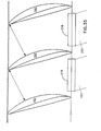
- Figures 13 and 13a show a two-row guide vane having a forward row 114 and aft row 116 of blades.
- the relationships between the blades 118 in the forward row with respect to the blades 120 in the aft row is similar to the relationships between corresponding blades as discussed above with respect to Figure 6.
- each of the blades 118 in the forward row of stationary guide vanes includes means 122 for adjusting pressure and flow velocity through the blower or pump during operation thereof at a predetermined speed of rotation.
- the means 122 includes means for mounting each of the forward blades 118 for pivotal movement about a point 126 located closely adjacent the trailing edge 128 of each blade 118 of the forward row 114.
- the means 122 also includes means for pivoting each forward blade 118 about said point 126 thereby changing the angle of attack of the forward row of blades 114 and changing the flow deflection of the forward blade and its corresponding aft blade.
- the means 130 for pivoting each forward blade 118 includes a servomechanism 132 mounted to effect, upon activation thereof, pivotal movement of each forward blade 118 about said point 126, means 134 for sensing, during operation of the blower or pump, a condition of flow (such as velocity and/or pressure) produced by the blower or pump and generating a signal in response thereto, means 138 for comparing the generated signal with a predetermined signal and generating a signal proportional to the differential thereof, means 140 for using the differential signal to actuate the servomechanism 132, and means 142 for causing the servomechanism 132 to rotate each blade 118 in the forward row by an amount proportional to the differential signal so generated thereby changing the angle of attack of each forward blade, said servo mechanism actuating means including a motor 142a, a drive shaft 142b, a gear box 142c, a pinion gear 142d and a spur gear 142e.
- the blade 118 has a shaft portion 118a that extends through an opening 129a formed in the annular or hub member 129 and through a pair of openings 131 a formed in the clevis 131.
- the shaft portion 128a is suitably splined or keyed (not shown) so as to rotate when the clevis 131 is rotated by the ring gear 142e.
- a pin 133 extends through the pair of openings 131b formed in the clevis 131 and a corresponding v-shaped slot formed in the ring gear 142e.
- rotation of the ring gear 142e clockwise will cause the blade 118 to rotate counterclockwise.
- Figures 13 and 13a show adjustable guide vanes designed as a multiple blade with symmetric forward blade arrangement for an axial flow blower.
- the forward blades 118 are shown in their standard or normal position x which corresponds to the blower performance at the design point. When the forward blades 118 are moved to position y, this corresponds to a condition of lower-than-normal capacity. When the forward blades 118 are moved to a position z, this corresponds to a condition for a larger-than-normal flow capacity. It will be understood that positions y and z for forward blades 118 are two extreme positions of such blades and indicates the relatively small turning angle of the forward blades 118. As previously mentioned, Figure 13 shows that the forward blades 118 are turned about an axis or point 126 located closely adjacent the trailing edge 128 of each blade 118 of said forward row 114.
- each forward blade 118 about its respective point 126 is done to provide proper dimensioning of the transition from the forward to the aft blade row at locations yK-yD and zK-zD.
- chord ch x of each aft blade 120 and a corresponding forward blade 118 becomes shorter, namely chy, with the forward blade 118 in position y for small capacity, and becomes longer, namely ch 2 , with the forward blade in position z for very large capacity when compared with the chord ch for the standard position as shown in Figure 13.
- the distance, yC-yB, between adjacent forward blades becomes smaller when the forward blade is in position y for smaller-than-normal capacity.
- the distance separating adjacent forward blades becomes larger, zC-zB, for the forward blades in position z for larger-than-normal capacity.
- the multiple blade with the forward blade in position y has a larger camber for the "combined" blade, i.e., each aft blade 120 and its corresponding forward blade 118.
- the multiple blade with the forward blade in position z has a smaller camber for the "combined" blade, i.e., each aft blade 120 and its corresponding forward blade 118, when the forward blade is in position x.
- the solidities of the multiple blade shown in Figure 13 are as follows:
- the blower of this invention with its capability to operate with very high pressure coefficients will have small diameters for a fixed pressure and consequently can be manufactured at low cost.
- the ability to adjust the stationary guide vanes will permit operation at high efficiency over a wide range of flow capacity. This feature cannot be achieved with conventional technology.
- the blower will operate at a very low noise level.
- the low noise level is due to the special impeller blades and guide vanes both of which have a very large flow deflection angle. Thus, the sources of noise are prevented from leaving the casing of the blower.
- the noise level can be kept at its low amount over a very wide range of flow and pressure.
- the low shaft speed together with the low specific speed permit this blower to operate in performance ranges where axial flow machines cannot now operate.
- the blower can use a diffuser 74, see Figure 1, at the discharge from the guide vanes in order to transform the remaining kinetic flow energy into pressure.
- the above-described combination of new concepts offer opportunities to use low-cost axial flow blowers in areas where same could not be previously used.
- centrifugal blowers can have impeller blades with backwardly curved, radially ending or forwardly curved blades and their guide vanes provide flow deceleration with corresponding pressure increase.
- the adjustability of the multiple blade system or changes in flow inlet angle and combined blade camber offer entirely new performance characteristics for both axial and centrifugal blowers and these new performance characteristics can be achieved automatically.
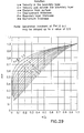
- Figure 18 shows the maximum amount of flow deceleration as a function of solidity for guide vanes. It shows the limit of flow deceleration which can be achieved without stalling. On the left hand ordinate of Figure 18 is shown the nomenclature which is used in this specification. On the right hand ordinate is shown the nomenclature for flow deceleration which is used in prior art literature. It is noted that the values of deceleration are indicated in Figure 18 as narrow band and not as a single line.
- Figure 18 forms the basis for design of such guide vanes. It also forms the basis of gap width and chord length within the multiple blade configuration or the relative position of forward and aft blades as a part of the multiple blade rows.
- the blade chord of the forward blade is preferably shorter than the chord of the aft blade, for example, with a guide vane blade configuration like that shown in Figure 12, excluding the part blades 102, the solidity of the forward blades may equal 0.665 and the solidity of the aft blades may equal 1.33.
- the methodology of guide vane designs consist in determining the maximum inlet angle and deflection that the multiple blade can achieve with the above solidities. It is always possible by reducing blade camber and/or solidity to design for less inlet angle and deflection.
- the total inlet angle is determined by analyzing separately the forward blade and the aft blade performance and then combining both.
- the maximum deceleration, from Figure 18, equals approximately 0.530 and the corresponding deflection equals 58.0°.
- the maximum deceleration equals approximately 0.680.
- the corresponding deflection ⁇ 2 11.4 *.
- deflection angles ⁇ . 2 are associated with high values of flow coefficient ( ⁇ ) and thus have higher flow velocities going through the impeller and entering the guide vanes. This requires fewer blades and lower solidity in the forward row of the multiple blade to reduce flow friction.
- high deflection angles a '2 are usually associated with low values of flow coefficient ( ⁇ ) and thus have lower flow velocities going through the impeller and entering the guide vanes. Thus, a larger number of blades and associated higher solidity in both forward and aft rows of the multiple blade is justified because of the lower values of flow friction.
- this invention also applies to centrifugal blowers. More specifically, this invention relates to the guide vanes or vaned diffuser used in centrifugal blowers.
- the vaned diffuser is located downstream by the impeller.
- the impeller can have airfoil type blades as shown in Figures 2 and 3, and it can have blade arrangements as shown in Figures 21 and 22.
- the impellers of centrifugal blowers can have blades which are backwardly curved, radially ending or forwardly curved. Each of these impellers can have a vaned or vaneless diffusing system following the impeller.
- centrifugal blowers with forwardly curved impeller blades In centrifugal blowers with forwardly curved impeller blades, the absolute velocity leaving the impeller is relatively large, just as in axial flow blowers. Thus, centrifugal blowers with forwardly curved impeller blades have a higher pressure coefficient ⁇ and a smaller impeller diameter than centrifugal blowers with backwardly curved blades. Under these circumstances, it is undesirable to discharge directly from the impeller into a scroll because the absolute velocity is high and the impeller diameter is small such that the volute length is relatively short. For the high absolute exit velocity, it is desirable to have a scroll volute of large length. This means a much larger diameter. As an alternate, the high velocity leaving the impeller must be reduced and this can be done in a vaned diffuser. However, the principles of this invention can be applied to any centrifugal blower.
- FIG. 19A is a sketch of diffuser of section 13.14 from the book by Church, A.H., CENTRIFUGAL PUMPS AND BLOWERS, published by John Wiley & Sons, 1945.
- the solidities of the guide vanes are quite similar to those of axial flow blowers.
- the flow has good guidance from location or line 1 C-1 B to the guide vane location at 1 A-1 K because the guide vanes guide the flow on both sides.
- the flow is guided only by one side of the blade 143.
- the distance 1-1 B becomes larger for large deflection angles as or low flow capacity and becomes smaller for small deflection angles ⁇ . 2 or larger flow capacity.
- the contour 1-1 B should conform to a logarithmic spiral or equivalent because such a contour conforms to a natural flow line without deceleration and therefore does not stall the flow and cause losses. This means that in the distance 1-1 B there occurs no deceleration and no corresponding transformation from flow velocity into pressure. It will be noted in Figure 19A that the distance 1-1 B equals about 7.0" and exceeds 50% of the guide vanes chord. In the centrifugal blower shown in Figure 19A, there is at the guide vane exit the distance 1 K-1 G which equals 6.87" where the flow is guided on one side by the blade 143 and on the other side by the scroll (not shown).
- the flow velocity is relative low at the guide vane exit when compared to the flow velocity at the guide vane entrance; thus, flow losses, if any, are very small at the guide vane exit.
- the guide vanes have parallel side walls 144 and 145 and constant width entrance (b 3 ) to exit (b 4 ).
- FIG. 20A illustrates the guide vanes for a centrifugal blower with multiple blades in which the number of blades 146 in the forward row is equal to twice the number of blades 147 in the aft row.
- the centrifugal blower of Figure 20A and the axial blower of Figure 13 has twice as many forward blades as aft blades. It will be noted that the flow is guided on both sides from the line 1 B-1 C to the line 1 A-1 K and the length of this flow channel is substantially longer than the length of the flow channel from the line 1B-1C to 1A-1K in Figure 19A.
- the distance 1-1 B in Figure 20A where the flow is guided on only one side of the blade 146 is only 2.80" long as compared to 7.0" in Figure 19A. This is due to the larger number of forward blades 146 used in the guide vane system of Figure 20A.
- the distance 1 K-1 G equals 6.25" as compared to 6.87" for the distance 1 K-1 G in Figure 19A.
- This is due to the use of a slightly larger number of aft blades 147 in Figure 20A as compared to the number of blades used in Figure 19A because the aft blades 147 of the multiple blade has a smaller chord of 9" than the single blade 143 of 13.0" of Figure 19A and therefore the solidity, namely ⁇ e 1.27, of the aft blades 147 of Figure 20A remains in a favorable range of solidity with a larger number of aft blades 147.
- the amount of deceleration c 2e /c 2i as a function of the solidity of the blades is governed by the value shown in Figure 18.
- the value C2e is the exit velocity of a set of blades and the value C21 is the corresponding inlet velocity of the same set of blades.
- the vaned diffuser entrance diameter D i equals 46" and the diffuser exit diameter D e equals 48".
- the number of forward blades (zi) is 48 and the number of aft blades ( Z2 ) is 24.
- the entrance pitch of the forward blades (t 1i ) equals 3.01" and the exit pitch of the forward blades (t 1e ) equals 3.14".
- the chord of each forward blade 146 equals 4.0".
- the entrance solidity of a forward blade all is equal to 1.33 and the exit solidity ⁇ 1e is equal to 1.27.
- the entrance diameter of the aft blade D 2i is equal to 48" and the exit diameter D 2e is equal to 54".
- the chord of the aft blade ch 2 is equal to 9.0".
- the entrance pitch of the aft blade (t2i) is equal to 6.28" and the exit pitch of the aft blade (t 2e ) is equal to 7.07".
- the entrance solidity of the aft blade a 2i is equal to 1.43 and the exit solidity of the aft blade a2e is equal to 1.27.
- FIGS 21 and 22 show the present preferred embodiment for a blower of a centrifugal turbomachine type constructed in accordance with the present invention.
- a portion of a centrifugal blower 148 is shown in Figure 21.
- Centrifugal blower 148 includes a stationary annular member 149, an impeller 150 positioned for rotation in said stationary annular member 149 and being radially spaced therefrom by an annular fluid path 152 which has a fluid inlet end 154 and a fluid outlet end 156 of larger diameter and which has a curved flow channel of progressively increasing area which extends from said fluid inlet 154 to said fluid outlet end 156.
- the impeller 150 has a series of impeller blade rows 158, 160 and 162 located in said fluid path 152 and being securely attached to the impeller 150.
- the centrifugal blower 148 also includes a series of guide vane rows 164, 166 and 168 located in said fluid path 152 and being securely attached to the annular stationary member 149.
- the guide vane rows are alternated with the impeller blade rows along the flow path 152.
- impeller blade row 158 and guide vane row 164 constitute a first pressure generating stage
- impeller blade row 160 and guide vane row 166 constitutes a second pressure generation stage
- impeller blade row 162 and guide vane row 168 constitutes a third pressure generation stage.
- Each impeller blade has an inner blade or hub portion 158a, 160a and 162a, an outer blade or tip portion 158b, 160b and 162b, a rounded leading edge 158c, 160c and 162c, and a relatively sharp trailing edge 158d, 160d and 162d.
- Each impeller blade has a combination of camber and solidity wherein, during operation of said impeller blades at the design point, the average outlet relative velocity w 2 is equal to or less than 0.6 times the average inlet relative velocity W1 at the impeller portion of said blades.
- the ratio of the average outlet relative velocity w 2 to the inlet relative velocity wi at the impeller portion is essentially constant from the hub portion to the tip portion.
- the angle of flow deflection 0 within the impeller blades is at least equal to approximately 50 or more.
- Each of the guide vanes includes at least a forward row of blades and an aft row of blades.
- the chord of each of the blades in the aft row is greater than the chord of each of the blades in the forward row.
- Each blade in the aft row cooperates with a corresponding blade in the forward row to form, during operation of the blower, multiple rows of blades.
- the axial distance "a" between the trailing edge of the forward blade and the leading edge of the aft blade and the circumferential distance d between the leading edge of the aft blade and the edge of the forward blade nearest the aft blade are within the limits described above and in equations 20 and 21 with respect to the axial flow blower.
- Each row of blades of the guide vanes have a combination of camber and blade solidity wherein during operation of the blower the direction of the discharge from the impeller blades is turned by said guide vane rows back to a reduced direction of flow angle or to the direction of the entry of the said row into said impeller blades and the deceleration of flow is approximately 0.66 or more, the value of 0.66 is equivalent to the deflection angle of 49 in an axial flow machine.
- the pressure coefficient 0 for each of said centrifugal blower stages is equal to at least approximately 1.5.
- Each of the blades in the forward row have a blade solidity equal to approximately 1.3 ⁇ 0.6; each of the blades in the aft row have a blade solidity equal to approximately 1.1 ⁇ 0.6.
- the absolute blade exit velocity of the impeller blades at the outlet C2 is greater than both the circumferential velocity u and the inlet relative velocity wi.
- the flow vector of the circumferential component of the relative velocity Wu1 of said impeller blades at the inlet is in a direction opposite to the direction of circumferential velocity u and the flow vector of the circumferential component of the relative velocity Wu2 of said impeller blades at the outlet is in the same direction as the circumferential impeller velocity u at least at one location between the hub and the tip of the impeller blade.
- the aft row of blades may include a plurality of part blades.
- the part blades will be positioned and have the same relationship as described with respect to axial flow blowers in Figure 11.
- each of the blades in the forward row of said guide vane rows may include means for adjusting pressure and flow velocity through the impeller blades during the operation of the blower at a predetermined speed of rotation.
- the pressure and flow velocity adjusting means includes means for mounting each of the forward blades for pivotal movement about a point located closely adjacent the trailing edge of each blade in the forward row and means for pivoting each forward blade about said point thereby changing the angle of attack of each blade of the forward row.
- This ratio can have values as presently used as long as the number of blades in the forward row is larger than the number of blades in the aft row. This ratio depends on the values of flow deceleration and their relation to solidity, as shown in Figure 18, and the related changes in channel width.
- a vaned diffuser or guide vanes result in a higher efficiency for a narrow range of flow capacity when compared to a vaneless diffusing system.
- the vaneless diffusing system has a higher efficiency outside the narrow range of flow capacity where the peak efficiency of the vaned diffuser is located.
- the multiple blade can have an adjustable camber and adjustable inlet angle when used in a vaned diffuses This will permit an extension of the high efficiency range for much of the flow capacity when using the vaned diffuser.
- the adjustable multiple blade diffuser can be expected to provide the vaned diffuser of a centrifugal blower with a wide range of high efficiency so that its efficiency is higher than that of a vaneless diffusing system over the entire range of flow capacity.
- the adjustment of the forward row of the multiple blade can, as previously described, be made manually or automatically.
- impeller blades for conventional turbomachines can be used to deflect the flow of fluid by approximately 45-49° without stalling. It will also be recalled that conventional pressure generating turbomachinery generates about 50% or more of the pressure in the impeller blades. It is also known that the remaining amount of pressure from conventional turbomachines is generated within outlet guide vanes. It has been found, however, that turbomachines of improved performance can be obtained by using impeller blades to deflect the flow of fluid without generating pressure therein and using outlet guide vanes to generate all or substantially all the pressure output of the turbomachine. Consequently, a turbomachine having nearly reactioniess impeller blades and outlet guide vanes which develop all or substantially all of the pressure produced has the above-described advantages and benefits.
- a turbomachine constructed in accordance with this invention and utilizing one row of guide vanes comprises a plurality of impeller blades mounted on a hub member for rotation, a plurality of stationary guide vanes mounted on the hub member, said guide vanes being located downstream from said impeller blades and through which flows the entire flow discharged by the impeller blades, and has a pressure coefficient equal to at least 1.0 or more.
- Each of the impeller blades has a hub portion, a tip portion, a rounded leading edge and a relatively sharp trailing edge.
- Each of the impeller blades has a combination of camber and blade solidity wherein, during operation of the blades at the design point, the outlet relative velocity ( W2 ) is equal to or greater than approximately 0.6 times the inlet relative velocity (wi) at the hub of the impeller, the ratio of the outlet relative velocity ( W2 ) to the inlet relative velocity (wi) at the hub is greater than at the tip, and the angle of flow deflection within the impeller blades is more than approximately 50°.
- Each of the guide vanes has a hub portion and a tip portion.
- Each of the guide vanes has a combination of camber and blade solidity wherein the direction of discharge from said impeller blades is turned by said guide vanes back to the direction of entry of said flow into said impeller blades while the absolute flow through said stationary guide vanes undergoes a substantial flow deceleration of approximately 0.66 or more at the hub location.
- Such a turbomachine is also characterized by the fact that the absolute value of the angle (a 1 ) between the inlet relative velocity (wi) and the axial through flow velocity (c m ) is approximately equal to the absolute value of the angle (a 2 ) between the outlet relative velocity (w 2 ) and the axial through flow velocity (c m ).
- the average value of relative velocity through the impeller blades between the hub and the tip is maintained substantially constant.
- the absolute value of the relative velocity through the impeller blades could be substantially constant only at one location of the impeller blades between the hub and the tip; at other locations the values are nonconstant.
- turbomachine is constant from the hub to the tip and the axial through flow velocity (c m ) is constant at the design point of the blower or pump.
- the turbomachine with solid guide vanes or relatively low deflecting angles ⁇ - 2 is characterized by operating with high flow coefficient ⁇ ⁇ 1.0.
- Another model of such a turbomachine is characterized in that the flow area at the hub of the impeller blade is substantially constant from the inlet to the outlet while the flow area at the inlet of the impeller blades is smaller than the flow area at the outlet of the impeller blades between the mean and the tip whereby the flow velocity through the impeller blades at the mean and the tip decelerates as the flow passes from the inlet to the outlet.
- Another model of such a turbomachine is also characterized in that it includes means to reduce high inlet velocities at the impeller blades at the inlet of said blades in which said means includes a hub member having an inlet diameter smaller than the outlet diameter whereby the axial flow area decreases from the inlet to the exit and the through flow velocity increases from the inlet to the exit of said impeller blades.
- Part blades may be used in the guide vanes of this turbomachine.
- a turbomachine having these characteristics may also be used with stationary inlet guide vanes located upstream of said impeller blades wherein each of the inlet guide vanes has a combination of camber and blade solidity which, during operation of the blower or pump, turn the circumferential component of the flow at the exit of said inlet guide vanes in a direction opposite to the direction of the circumferential impeller velocity (u).
- the dimensionless flow coefficient 0, pressure coefficient 0 , specific speed n s , and hub ratio v are used to design a pump or blower of the turbomachine type of this invention.
- the complete formulas for these dimensionless coefficients are set forth above.
- blower designs were selected for further evaluation; these blower designs are identified as Unit 2 with two row guide vanes and 5-5 blades (i.e., five blades in the forward row and five blades in the aft row) and Unit 3 with two row guide vanes and 10-5 blades in Table 2 and Figures 16 and 17.
- the forward row of guide vanes has a larger angle of attack and the performance of both units has slightly more pressure and lower values of flow capacity than Figure 17.
- the Unit 3 with two row guide vanes and 10-5 blades outperforms Unit 2 with two row guide vanes and 5-5 blades.
- This invention also relates to a method for producing pressurized fluid.
- the method comprises the steps of forming a fluid flow path, generating a flow of fluid through said fluid flow path, deflecting the flow of fluid as same flows through said fluid flow path while simultaneously maintaining the average outlet relative velocity (w 2 ) approximately equal to the inlet relative velocity (w 1 ) prior to said deflection at least at one point in the fluid flow path, and generating pressure by turning back the flow of fluid discharged from the impeller by an amount approximately equal to the amount of deflection of the fluid by maintaining the rates of the axial through flow velocity through flow velocity to the deflected outlet velocity before the generation of said pressure equal to 0.66 or less.
- the invention also relates to a method producing pressurized fluid comprising the steps of forming a fluid flow path, generating a flow of fluid through said fluid flow path, deflecting the flow of fluid by approximately 50° or more while simultaneously maintaining the average outlet relative velocity (w 2 ) following said deflection approximately equal to or less than relative velocity (wi) prior to said deflection at least at one point in its fluid flow path, and generating substantial pressure by turning back the flow of absolute fluid velocity by at least approximately 49 or more while simultaneously decelerating the flow of fluid by maintaining the ratio of the axial through the fluid flow path to the outlet velocity before the generation of said pressure equal to approximately 0.66 or less.
- Figure 14 shows a blower having three rows in the guide vanes.
- the first row 174 contains 24 NACA 650912 blades 176 from the 65 series.
- the second row 178 contains 16 NACA 651210 blades 180 from the 65 series. Each of these blades in the second row has a chord of 3?" and a stagger angle ⁇ 2 of 46.9".
- the third row 182 contains eight NACA 652110 blades from the 65 series. Each of these blades has a chord of 71" and a stagger angle ⁇ 3 of 74°.
- the axial distance a 2 separating the second row 178 from the third row 182 of blades is 0.06".
- the pitch t 2 at the hub for the second row 178 is 1.963".
- the circumferential distance d 2 is 0.85".
- the pitch t 3 at the hub for the blades 184 in the third row 182 is 3.926".
- the stagger angle y 3 is 74°.
- a blower having three rows in the guide vanes is required for large flow deflection angles ⁇ ° 2 in the guide vane blades, i.e., greater than approximately 70°.
- the design of a blower having three rows of blades in the guide vane is similar to the design of a blower having two rows of blades in a guide vane, except, of course, that consideration must be given to the blade to be used in the third row, the axial spacing "a" between the blades in the second and third rows and the circumferential distance d between each two pairs of rows, particularly in the third row and a corresponding blade in the second row.
- the information set forth above with respect to a blower having two rows of blades in the guide vane is applicable with respect to the relationship between the second and third rows of blades in the guide vanes.
- Figure 14 shows the present preferred embodiment for a three row pump or blower of the turbomachine type constructed in accordance with the subject invention in which the guide vanes turn back the flow of fluid between 70 to 80 providing that the three row guide vane configuration contains four forward blades to two aft blades to one third row blade (rather than three forward row blades to two aft blades to one third row blade).
- the axial length of the pump or blower is limited, four forward blades to two aft blades to one third row blade can be used; when fewer blades in the first row are preferred, the three row guide vane configuration will use three forward blades to two aft row blades to one third row blade.
- This invention also relates to the design of diffusers incorporating a boundary layer removal system.
- the purpose of a diffuser is to reduce fluid velocity in an orderly manner and transform the reduction of fluid velocity into static pressure.
- a diffuser is generally identified by its included angle of the diffusing walls and the ratio of diffuser length M over the inlet radius D/2 or inlet diameter D.
- Figure 23 shows a recommended included angle for two-dimensional and conical diffusers. Figure 23 indicates that the included angle is not constant but varies with the ratio 2M/D or the relative length of the diffuser. For a ratio of 2M/D equals 10, the recommended included angle is 7.5 for the conical diffuser and for larger ratios of 2M/D the recommended included angle is smaller whereas for lower values of 2M/D the included angle can be larger.
- Figure 24 shows recommended the "equivalent angle" (25 E ) as the ordinate. Equivalent angle is defined as the included angle of a conical diffuser with identical inlet and outlet areas, and length, relative to that of the diffuser in question.
- Figure 24 indicates that the equivalent angle 25 E is not only a function of the ratio 2M/D but it also varies of the value of the center body ratio D H /D T .
- Figures 23 and 24 indicate that for large diffusion ratios or large values of outlet to inlet area, diffusers of substantial length are needed because the included angle or equivalent angle is of a very low value and this angle reduces in value with increased diffuser length. It will be noted that diffuser performance is also affected by flow turbulence, Reynolds number and boundary layer thickness u. at the diffuser inlet. The information shown in Figures 23 and 24 is based on a Reynolds number of 2x10 5 or above, based at the diffuser inlet dimensions. The effect of flow turbulence and inlet boundary layer are much more difficult to assess and, thus, are frequently neglected.
- a diffuser using means for controlling or removing the boundary layer constructed in accordance with this invention permits large increases in the value of the included angle or equivalent diffuser angle. In turn, this results in a substantial reduction in the length of the diffuser required. Consequently, space, weight and cost are saved as a result of the reduction in length. Since a diffuser constructed in accordance with this invention, must operate over a wide range of fluid velocities at the diffuser inlet and an associated range of fluid pressures, the range of performance will, in turn, cause a corresponding range of Reynolds numbers at the diffuser inlet. This range of Reynolds numbers will result in a related range of boundary layer thickness on the wall surface of the diffuser. The boundary layer removal system of this invention must operate efficiently under all these operating conditions.
- Diffusers are also used in a large variety of sizes to which the boundary layer removal system must be adopted. Since many fluids, e.g., air, contain varying amounts and sizes of solids, such as dust, in their fluid stream, due to the reduced flow velocity that exists in the boundary layer as compared to the flow velocity that exists in the main flow, such particles of solids are frequently deposited on the surface of the boundary layer.
- the boundary layer removal system of this invention is designed to take into account all of the above characteristics to operate successfully under the varying operating conditions.
- Diffusers are typically of two different configurations.
- Figure 23 shows a typical configuration with expanding diffusion angle 28.
- An alternate diffuser configuration has a converging center body as shown in Figure 24. In either case, the flow area increases in it value from diffuser inlet to diffuser exit. Thus, the flow velocity decreases from diffuser inlet to diffuser exit and the static pressure increases accordingly from diffuser inlet to diffuser exit.
- Figure 25A shows a complete arrangement of an axial flow blower 174 having inlet vanes 176, a rotor 178, impeller blades 180, stationary outlet guide vanes 182 and a converging center body diffuser 184.
- Figure 25B shows the static pressure that exists at each of various locations along the fluid flow path 186.
- the highest static pressure exists at the diffuser exit 184a.
- the static pressure is zero, i.e., atmospheric, while the lowest pressure (a negative pressure) is found at the impeller entrance.
- a substantial increase in pressure exists at the impeller exit and the static pressure increases continuously from the impeller exit through the guide vanes to the diffuser exit 184a.
- Figure 26 shows a portion of a blower containing means 190 for controlling the boundary layer which, during operation of the blower, forms on the flow directing surfaces of the fluid flow path through said blower.
- the blower has a fluid flow path 192 defined in part, by the outer surface 194 of the diffuser 196 and the inner surface 198 of the tubular housing 200.
- the means 190 include an annular fluid passage 202 having an inlet or first predetermined part 202a for receiving within said fluid passage 202 a portion of the boundary layer to be removed from the surface 194 and an outlet or second predetermined portion 202b for returning the removed boundary layer to the fluid flow path 192.
- Figure 27 shows a portion of a blower including means 206 and 208 for removing a portion of the boundary layer from flow directing surfaces 210 and 212 included in the fluid flow path 214 of said blower.
- the diffuser 216 has a converging outer surface 210 while the housing 218 for the blower has, taken in the direction of flow of fluid, a diverging inner surface 212.
- the means 206 includes a fluid passage 220 having an inlet 220a and an outlet 220b located upstream of the inlet 220a.
- the means 208 includes a fluid flow passage 222 having an inlet 222a and an outlet 222b located upstream of said inlet 222a.
- Each of the means 206 and 208 will remove portions of the boundary layer formed, respectively, on the converging surface 210 and the diverging surface 212.
- the fluid passages 220 and 222 are in fluid communication, at their inlets, with a substantial portion of the flow directing surfaces 210 and 212. It is preferred that a portion of the boundary layer be removed from a substantial portion of said surfaces; however, improved performance is obtained even when the fluid passages are not in fluid communication with a substantial portion of the boundary layer formed on said surfaces 210 and 212.
- Figure 28 shows a blower 226 having means 228 and 230 for removing boundary layer from flow directing surfaces 232 and 234 contained in the fluid flow path 236 formed through said blower 226.
- the means 228 and 230 include, respectively, fluid flow passages 238 and 240 formed outside of the fluid flow path 236 but disposed in fluid communication therewith through a plurality of openings 238a and 240a.
- the openings 238a and 240a constitute a plurality of perforations formed in an annular layer of material, said layer forming, respectively, a part of the outer surface 232 for the diffuser and the inner surface 234 of the housing for the blower.
- the fluid passages 238 and 240 have, respectively, outlets 238b and 240b for returning the removed boundary layer to the fluid flow path 236.
- Said fluid passages 238 and 240 also include means 242 and 244 for removing particulate matter from the portion of the boundary layer removed from said flow directing surfaces 232 and 234.
- said means 242 and 244 include an electronic particulate removal means.
- the blower 226 includes impeller blades 246, guide vanes 248, a motor 250, a rotor 252, and an inlet portion covered with a hemispherically shaped cap 254.
- impeller blades 246 are essentially reactionless and the guide vanes 248 are constructed in accordance with the invention described above, a blower may be constructed using a much smaller diameter than previously possible. In turn, this means that a smaller motor 250 will be required.
- blowers or pumps are frequently driven by electric motors.
- the electric motor driving the impeller blades is usually located inside the cylindrical shell carrying the guide vanes of the blower or pump. As shown in Figure 28, the electric motor 250 is located upstream of the diffuser 233.
- the heat developed from operation of the electric motor 250 is conducted to the motor casing and from the motor casing to the outer cylindrical structure supporting the guide vanes.
- the air moving along the guide vane hub and the cylindrical structure removes excess heat by conduction.
- Some motors may use an interior fan to circulate the air inside the motor. Generally, this air is not connected to ambient air; the purpose of such a fan is to avoid hot spots inside the electric motor and assist in carrying the heat to the motor casing.
- blowers and pumps constructed in accordance with this invention have pressure coefficients three to four times as large as those of conventional blowers and pump.
- the diameter of blowers and pumps constructed in accordance with this invention D H compared to the diameter of conventional blowers and pumps D equals:
- the diameter of blowers and pumps constructed in accordance with this invention D N will equal approximately 0.577 to 0.500 of the diameter of conventional blowers and pumps.
- the motor diameter of blowers and pumps constructed in accordance with this invention may be reduced to about one half the motor diameter of conventional blowers and pumps.
- the means 228 and 240 for controlling boundary layer within the blower 226 includes means for attenuating noise during operation of the blower.
- Said means includes two or more openings, each of which has a longitudinal axis disposed perpendicular to the flow directing surface in which said openings are formed, e.g., the openings 238A, 238B, 240A and 240B are circular in cross-section.
- boundary layer thickness in a diffuser requires the calculation of boundary layer thickness in an adverse pressure gradient.
- the growth of a turbulent boundary layer under the conditions of an adverse pressure gradient can only be approximately calculated, provided there is no flow x' w 3 6separation.
- Prediction of boundary layer thickness is H ⁇ x ⁇ x.far from an exact sciencî ⁇ rious investigators px 3 x' 4have given substantially different formula eseparation.
- Prediction of boundary layer thickness is far from an exact sciencî ⁇ rious investigators have given substantially different formula even for the simple case of constant velocity and zero pressure gradient.
- the amount of boundary layer flow to be removed in a specific case can best be estimated by calculating the boundary layer thickness at the required Reynolds number and assuming constant velocity and zero pressure gradient. Subsequently, the effects of the boundary layer removal system and adverse pressure gradient can be estimated.
- the adverse pressure gradient is a direct function of the degree of diffusion in the diffuser.
- Calculations of the quantity of the boundary layer flow are based on turbulent boundary layers because the value of the Reynolds number in diffusers used downstream of axial flow blowers is of such a quantity that laminar flow can be excluded.
- the impeller of a blower generates a high degree of turbulence which will prevent laminar flow.
- Figure 29 shows turbulent boundary layer profiles and presents velocity distribution within the boundary layer as a function of the shape parameter F.
- s/u. is plotted on the abscissa and k/K is plotted as the ordinate.
- the nomenclature is identified in Figure 29.
- the boundary layer thickness has the value 7-4.
- the boundary layer thickness will be less than the values of 7-4 or, 7-8 as shown in Figure 30.
- the boundary layer thickness should approximate that of curve 1-5 shown in Figure 33. It will be noted that the above boundary layer thicknesses and respective flow velocities are assumed to exist at the design point of the blower system.
- the means for controlling boundary layer contemplated by this invention must function over the entire range of flow and pressure.
- the maximum boundary layer thickness to be removed will have a value of 7-6 as shown in Figure 30 while the average boundary layer thickness to be removed at the design point will be considerably less, e.g., the boundary layer thickness represented by the values 7-5 as shown in Figure 30.
- the means for controlling boundary layer as contemplated by the herein invention will remove the boundary layer likely at a single location near the end of the duct or diffuser.
- the difference in operation and corresponding flow losses between a cylindrical duct, which has a constant pressure gradient in the case of no friction, and a diffuser with adverse pressure gradient is substantially changed.
- the diffuser can be substantially shorter, flow losses can be reduced and the diffuser angle is no longer limited to small values as shown in Figures 23 and 24. Diffusers having large diffuser angles may be used without stalling or losses.
- boundary layer removal can be made continuous along the diffuser wall as shown in Figure 28.
- the boundary layer thickness represented by 7-6 in Figure 30 equals approximately 1/2 of the boundary layer thickness represented by 7-8.
- the boundary layer thickness of 7-6 has been determined on the basis of the' above theoretical considerations and certain tests.
- the factor "1/2" in formula (27) considers the substantial change of using a continuous boundary layer removal system and going from a constant to an adverse pressure coefficient, as described above.
- Several calculations have indicated that the maximum amount of boundary layer flow to be removed from a diffuser with boundary layer control means equals about 2% of the flow of the blower at its design point for a blower - diffuser system.
- Figure 31 shows a hollow air foil 260 used to discharge back into the fluid flow path relatively large amounts of removed boundary layer flow.
- the hollow air foil 260 can be used as a single air foil or as a multitude of separate air foils located at the appropriate location within the blower.
- the specific location of the hollow air foils 260 is a function of pressure differential required for boundary layer removal and the local static pressure within Figure 31, the hollow air foil 260 is connected to a fluid flow passage 262 which conveys a boundary layer removed from a point downstream of the location of the hollow air foil 260 to the hollow air foil 260 for return to the fluid flow path.
- FIG 31 A is shown a hollow blade 266a which can be used in lieu of one or more of the blades 266 shown in Figure 31.
- the blade 266a has a hollowed out portion 266b which extends from a point adjacent the hub to a point adjacent the tip of the blade.
- the opening 266b has an outlet 266c. It will be understood that when the blade 266a is used in the guide vane configuration shown in Figure 31, the hollow portion 266b will be disposed in fluid communication with an appropriately located fluid passage (not shown).
- the blade 266a is used where relatively large amounts of boundary layer are to be removed and returned to the fluid flow path. In order to provide adequate space for the formation of the outlet opening 266c, it will be appreciated that an appropriate adjustment in the blade camber must be made.
- blade 266a When blade 266a is used in the guide vane configuration shown in Figure 31 in lieu of one or more blades 266, it will be understood that the boundary layer is returned to the fluid flow path adjacent the trailing edge of the aft blades.
- the boundary layer upon being returned to the fluid flow path, passes through the outlet 266c in a downstream direction.
- Figure 32 shows a plurality of fluid passages 270 each of which is connected to a corresponding circular opening 272 for returning the removed boundary layer to the boundary layer at a location upstream of the point where the boundary layer was originally removed.
- Each of the openings 272 are preferably circular in cross-section in order to attenuate noise during operation of the blower.
- the use of openings 272 is to permit the return of the removed boundary layer back into the boundary layer itself.
- an outlet 274 may be used in lieu of the outlet 272.
- the outlet 274 includes a stream lined member 276 to reduce noise and friction as the fluid flows past the outlet 274.
- the member 276 extends in an upstream direction away from the outlet 274. It will be understood that the outlets 272 and 274 may be located at the entrance, mean location or near the exit of a single row or two row guide vane system.
- FIG 35 shows the use of relatively large outlets 278 for the fluid passages 280.
- the outlets 278 may return the removed boundary layer at the exit of the guide vanes 282, as shown in Figure 35; however, the outlets 278 may also be located near the inlet of the guide vanes 282 or in the middle location of the guide vanes 282.
- the boundary layer flow is removed at a certain location.
- the pressure at the location is known.
- a pressure diagram similar to that shown in Figure 25B, will give an indication of the pressure existing at that location.
- the amount of boundary layer flow to be removed can be estimated from formula (27).
- the return location for the boundary layer flow can be selected from a pressure diagram similar to that shown in Figure 25B. This will give the local pressure at the return location and the respective local velocity can be calculated from the impeller or guide vane configuration.
- the reduced pressure at the return location of the boundary layer flow compared to the pressure at boundary layer flow entrance can be used to return the flow and accelerate it to the velocity of the local flow at that specific location.
- an ejector type pump can be used as the driving energy of an ejector type pump to provide pumping action to return the boundary layer of flow into the main stream.
- Such ejector action can be used with a boundary layer flow discharge nozzle or outlet configuration similar to that shown in Figures 31 and 31 A, and also with . the configuration of the type shown in Figure 34. In this manner, an appropriate location for the return flow for the removed boundary layer can be selected to have the complete system operate efficiently.
- the herein invention relates to a method of removing a portion of the boundary layer formed on flow directing surfaces of a fluid flow path comprising the steps of forming a fluid flow path having flow directing surfaces, generating a flow of fluid through said flow path along said flow directing surfaces while simultaneously forming a boundary layer on said flow directing surfaces, forming a fluid flow passage, and removing a portion of the boundary layer from a first part of said boundary layer formed on at least one of said flow directing surfaces and returning said portion of said boundary layer to the fluid flow path located upstream of said first part.
- the herein invention also relates to the method as described above in which the step of removing a portion of said boundary layer includes effecting a thermal transfer of energy to said removed boundary layer portion before said removed boundary layer portion is returned to the fluid flow path at said second part.
- the herein invention also relates to the method as aforedescribed in which the step of removing a portion of the boundary layer includes returning said portion of said removed boundary layer to a second part of said flow path, said second part being located upstream of said first part, by simultaneously connecting said fluid passage in fluid communication with the first and second parts.
- the herein invention also relates to the method as aforedescribed in which the step of forming a fluid of passage includes forming said fluid passage outside of said fluid flow path.
- the herein invention relates to a method of producing fluid pressure at reduced noise levels. It has been found that with the use of impeller blades constructed in accordance with this invention, a much thinner boundary layer exists on the impeller blades. Since the boundary layer, being disclaimed from the impeller blades, impacts against the guide vanes, the greater amount of boundary layer there is, the greater amount of noise that is produced when the boundary layer impacts on the guide vanes. By reducing the thickness of the boundary layer through use of impeller blades constructed in accordance with this invention, there is a corresponding reduction in the amount of noise that is produced with the pump or blower of this invention.
- one of the methods of this invention relates to the producing of pressurized fluid at reduced noise levels comprising the steps of forming a fluid flow path, generating a flow of fluid through said fluid flow path, deflecting the flow of fluid as same flows through the fluid flow path while simultaneously maintaining the average relative velocity following said deflection approximately equal to the relative velocity prior to said deflection at least at one point in the fluid flow path, and generating pressure by turning back the flow of absolute fluid velocity by an amount approximately equal to the amount of absolute velocity deflection of the fluid while simultaneously decelerating the flow of fluid.
- FIG. 1 shows an apparatus 50 constructed in accordance with this invention which uses essentially reactionless impellers 70 in combination with downstream guide vanes 60 to turn the direction of flow discharge from the impeller blades to the direction of entry of said flow into said impeller blades while the absolute flow through said guide vanes undergoes a substantial flow deceleration of at least approximately 0.66 or more at the hub location and the pressure coefficient for the blower or pump 50 is equal to at least 1.0 or more.
- the blower 50 also includes means for removing a portion of the boundary layer from a first predetermined part, at the inlet 75a to fluid passage 75, of one of said flow directing surfaces 74 located downstream of the impeller blades 70 and returning said removed boundary layer to the fluid flow path, through outlet 75b, at a second predetermined part of said flow directing surface 74 located upstream of said first predetermined part.
- the means for removing a portion of the boundary layer from one of the flow directing surfaces 74 contained in the fluid flow path 76 includes a fluid passage 75 which extends generally in the direction of the flow of fluid through said fluid flow path, said fluid passage 75 having a first or inlet portion 75a disposed in fluid communication with a first predetermined part of said boundary layer and a second or outlet portion 75b disposed in fluid communication with the second predetermined part of said boundary layer.
- the inlet 75a to and the outlet 75b from the fluid passage 75 is circular in cross-section in order to attenuate noise as fluid passes through the blower 50.
- the means 190 of Figure 26, means 206 and 208 of Figure 27 and means 228 and 230 of Figure 28 may also be used in combination with the impeller blades and guide vanes as aforedescribed.
- the aforesaid boundary layer removal means may be varied or modified as disclosed and described in connection with Figures 31-35.
- An apparatus constructed in accordance with this invention may include inlet guide vanes such as guide vanes 72 shown in Figure 1.
- the outlet guide vanes may comprise a plurality of single, solid blades, a two row guide vane configuration or a three row guide vane configuration all as shown and described in connection with Figures 1 and 10-13 and 15.
- the blower or pump of this invention includes centrifugal blowers such as are shown in Figures 20-22.
- the herein invention relates to a method of producing pressurized fluid comprising the steps of forming a fluid flow path, generating a flow of fluid through said fluid flow path, deflecting the flow of fluid as same flows through said fluid flow path while simultaneously maintaining the average relative velocity following said deflection approximately equal to the relative velocity prior to said deflection at least at one point in the fluid flow path, and generating pressure by turning back the flow of fluid by an amount approximately equal to the amount of deflection of the fluid while simultaneously decelerating the flow of fluid by maintaining the ratio of the axial through flow velocity through the fluid flow path to the outlet velocity before the generation of said pressure equal to approximately 0.66 or less.
- the herein method also relates to the method as aforedescribed in which the step of deflecting the flow of fluid is achieved substantially without generation of any pressure at least at one point in the fluid flow path.
- the herein invention also relates to a method of producing pressurized fluid comprising the steps of forming a fluid flow path, generating the flow of fluid through said fluid flow path, deflecting the flow of fluid as same passes through said fluid flow path by approximately 50° or more while simultaneously maintaining the average relative velocity following said deflection approximately equal to or less than the relative velocity prior to said deflection at least at one point in the fluid flow path, and generating substantial pressure by turning back the flow of fluid by an amount greater than approximately 49 or more while simultaneously decelerating the flow of fluid by maintaining the ratio of the axial through flow velocity through the fluid flow path to the outlet velocity before the generation of said pressure equal to approximately 0.66 or less.
- the herein invention also relates to a method of removing a portion of the boundary layer formed on flow directing surfaces, said method comprising the steps of forming a fluid flow path having flow directing surfaces, generating a flow of fluid through said flow path along said flow directing surfaces while simultaneously forming a boundary layer on said flow directing surfaces, forming a fluid flow passage, and removing a portion of the boundary layer from a first part of said boundary layer formed on at least one of said flow directing surfaces and returning said portion of said boundary layer to said fluid flow path at a location upstream of said first part by simultaneously connecting said fluid flow passage in fluid communication with said first part and said upstream location.
- the herein invention also relates to the method as aforedescribed in which the step of returning said portion of said boundary layer includes effecting a thermal transfer of energy with said removed boundary layer before said boundary layer is returned to the fluid flow path at said upstream location.
- the herein invention also relates to the method as aforedescribed in which the step for forming a fluid passage includes forming said fluid passage outside the said fluid flow path.
- the herein invention also relates to a method as aforedescribed in which the step for forming a fluid passage includes forming at least two fluid passages outside of said fluid flow path, and the step for removing a portion of the boundary layer includes removing portions of said boundary layer from at least two first parts of said boundary layer formed on at least one of said flow directing surfaces and returning each of said portions of said boundary layer to a respective one of at least two points located upstream of said two first parts by simultaneously connecting each of said fluid passages in fluid communication with the respective one of said first parts and said points.
- the herein invention also relates to a method of controlling boundary layer formed on a flow directing surface, said method comprising the steps of forming a fluid flow path having flow directing surfaces, generating a flow of fluid through said fluid flow path and along said flow directing surfaces while simultaneously forming a boundary layer on said flow directing surfaces, forming a fluid flow passage, and controlling the boundary layer thickness on at least one of said flow directing surfaces by removing a portion of said boundary layer from a plurality of first parts of said boundary layer formed on said flow directing surface and returning each of said portions of said boundary layer to said fluid flow path at a respective one of a plurality of parts located upstream of said first parts by simultaneously connecting said fluid passage in fluid communication with said first parts and said points.
- the herein invention also relates to a method of removing a portion of the boundary layer formed on flow directing surfaces, said method comprising the steps of forming a fluid flow path having spaced apart flow directing surfaces, forming a first fluid passage in one of said spaced apart flow directing surfaces outside the said fluid flow path, forming a second fluid passage in the other said spaced apart flow directing surface outside the said fluid flow path, generating a flow of fluid through said fluid flow path along said flow directing surfaces, removing portions of the boundary layer from a plurality of first parts of said boundary layer formed on one of said flow directing surfaces and returning each of said portions of said boundary layer to a respective one of a plurality of points located upstream of said first parts by connecting said first fluid flow passage in fluid communication with said first parts and said points, and removing portions of the boundary layer from a plurality of first parts of the other flow directing surface and returning each of said portions as said boundary layer to a respective one of a plurality of points located upstream of said first parts of the other flow directing surface
- the herein invention also relates to a method of producing pressurized fluid at reduced noise levels comprising the steps of forming a fluid flow path, generating a flow of fluid through said fluid flow path, deflecting the flow of fluid as same flows through the fluid flow path while simultaneously maintaining the average relative velocity following said deflection approximately equal to the relative velocity prior to said deflection at least at one point in the fluid flow path, and generating pressure by turning back the flow of absolute fluid velocity by an amount approximately equal to the amount of absolute velocity deflection of the fluid while simultaneously decelerating the flow of fluid.
- the herein invention also relates to a method of producing pressurized fluid at reduced noise levels comprising the steps of forming a fluid flow path having flow directing surfaces, generating a flow of fluid through said fluid flow path along said flow directing surfaces while simultaneously forming a boundary layer on said flow directing surfaces, deflecting the flow of fluid as same flows through the fluid flow path while simultaneously maintaining the average relative velocity following said deflection approximately equal to the relative velocity prior to said deflection at least at one point in the fluid flow path, generating pressure by turning back the flow of absolute fluid velocity by an amount approximately equal to the amount of absolute velocity and deflection of the flow while simultaneously decelerating the flow of fluid, forming a fluid flow passage, and removing a portion of the boundary layer from a first part of said boundary layer formed on at least one of said flow directing surfaces and returning said portion of said boundary layer to said fluid flow path at a location upstream of said first part by simultaneously connecting said fluid passage in fluid communication with said first part and said upstream location.
- the herein invention also relates to a method of producing pressurized fluid comprising the steps of forming a fluid flow path having flow directing surfaces, generating a flow of fluid through said flow path along said flow directing surfaces while simultaneously forming a boundary layer on said flow directing surfaces, deflecting the flow of fluid as same flows through said fluid flow path while simultaneously maintaining the average relative velocity following said deflection approximately equal to the relative velocity prior to said deflection, generating pressure by turning back the flow of fluid by an amount approximately equal to the amount of deflection of the fluid while simultaneously decelerating the flow of fluid by maintaining the ratio of the axial through flow velocity through the fluid flow path to the outlet velocity following the generation of said pressure equal to approximately 0.66 or less, forming a fluid flow passage located outside of said fluid flow path and removing a portion of the boundary layer from a first part of said boundary layer formed on at least one of said flow directing surfaces and returning said portion of said boundary layer to the fluid flow path upstream of first part by simultaneously connecting said fluid passage in fluid communication with said first part and the fluid
- the invention described herein may be applied to apparatuses of the turbomachine type including blowers, compressors, pumps, turbines, fluid motors and the like. Additionally, it may be applied to turbomachines utilizing inlet guide vanes.
Landscapes
- Engineering & Computer Science (AREA)
- Mechanical Engineering (AREA)
- General Engineering & Computer Science (AREA)
- Physics & Mathematics (AREA)
- Fluid Mechanics (AREA)
- Geometry (AREA)
- Structures Of Non-Positive Displacement Pumps (AREA)
Applications Claiming Priority (2)
| Application Number | Priority Date | Filing Date | Title |
|---|---|---|---|
| US200113 | 1988-05-27 | ||
| US07/200,113 US4981414A (en) | 1988-05-27 | 1988-05-27 | Method and apparatus for producing fluid pressure and controlling boundary layer |
Publications (2)
| Publication Number | Publication Date |
|---|---|
| EP0343888A2 true EP0343888A2 (fr) | 1989-11-29 |
| EP0343888A3 EP0343888A3 (fr) | 1990-09-19 |
Family
ID=22740389
Family Applications (1)
| Application Number | Title | Priority Date | Filing Date |
|---|---|---|---|
| EP19890305130 Withdrawn EP0343888A3 (fr) | 1988-05-27 | 1989-05-19 | Méthode et appareil de production de pression d'un fluide et de contrôle de la couche limite |
Country Status (2)
| Country | Link |
|---|---|
| US (1) | US4981414A (fr) |
| EP (1) | EP0343888A3 (fr) |
Cited By (11)
| Publication number | Priority date | Publication date | Assignee | Title |
|---|---|---|---|---|
| GB2298458A (en) * | 1995-03-02 | 1996-09-04 | Lucas Aerospace Power Equip | Cooling electromechanical apparatus |
| US6082966A (en) * | 1998-03-11 | 2000-07-04 | Rolls-Royce Plc | Stator vane assembly for a turbomachine |
| EP1077310A1 (fr) * | 1999-08-18 | 2001-02-21 | Siemens Aktiengesellschaft | Stator à aubes |
| EP1674664A2 (fr) | 2004-12-21 | 2006-06-28 | United Technologies Corporation | Ailette du guidage de moteur de turbine et arrangement |
| WO2012080053A1 (fr) * | 2010-12-15 | 2012-06-21 | Alstom Technology Ltd | Compresseur axial |
| EP2615262A2 (fr) * | 2012-01-11 | 2013-07-17 | General Electric Company | Diffuseur comportant un actionnement fluidique |
| EP2256299A3 (fr) * | 2009-04-24 | 2014-04-09 | Pratt & Whitney Canada Corp. | Déflecteur pour ensemble d'anneau d'aube de moteur de turbine à gaz |
| RU2586426C2 (ru) * | 2013-05-03 | 2016-06-10 | Текспейс Аеро С.А. | Статор осевой турбомашины с элеронами в хвостовиках лопаток |
| WO2016176605A1 (fr) * | 2015-04-30 | 2016-11-03 | Concepts Nrec, Llc | Passages de débit dans un diffuseur, et procédés correspondants de conception d'un tel diffuseur |
| CN108799202A (zh) * | 2017-04-27 | 2018-11-13 | 通用电气公司 | 具有包括导流板的排放槽的压缩机设备 |
| CN112594064A (zh) * | 2020-11-25 | 2021-04-02 | 北京航空航天大学 | 一种基于轴流压气机级间测量参数的s2流场诊断方法 |
Families Citing this family (44)
| Publication number | Priority date | Publication date | Assignee | Title |
|---|---|---|---|---|
| SE500471C2 (sv) * | 1991-07-09 | 1994-07-04 | Flaekt Ab | Ledskeneanordning i en axialfläkt |
| JP2735730B2 (ja) * | 1992-03-11 | 1998-04-02 | 日機装株式会社 | ディフューザポンプのディフューザベーン |
| KR950007521B1 (ko) * | 1992-08-14 | 1995-07-11 | 엘지전자주식회사 | 시로코우 팬 |
| US6048363A (en) * | 1997-05-13 | 2000-04-11 | Nagyszalanczy; Lorant | Centrifugal blood pump apparatus |
| US6622724B1 (en) * | 2000-06-19 | 2003-09-23 | Respironics, Inc. | Impeller and a pressure support system and method using such an impeller |
| US6543997B2 (en) * | 2001-07-13 | 2003-04-08 | General Electric Co. | Inlet guide vane for axial compressor |
| CA2374989A1 (fr) * | 2002-03-08 | 2003-09-08 | Andre Garon | Dispositif d'assistance ventriculaire comprenant une pompe a sang hybride a double entree |
| CA2428741A1 (fr) * | 2003-05-13 | 2004-11-13 | Cardianove Inc. | Pompe a sang helicocentrifuge a double canal d'entree |
| JP4590227B2 (ja) * | 2004-08-04 | 2010-12-01 | 株式会社日立製作所 | 軸流ポンプ及び斜流ポンプ |
| US8157518B2 (en) * | 2007-03-05 | 2012-04-17 | Xcelaero Corporation | Low camber microfan |
| WO2008109036A1 (fr) * | 2007-03-05 | 2008-09-12 | Xcelaero Corporation | Ventilateur de refroidissement à rendement élevé |
| US7819641B2 (en) | 2007-03-05 | 2010-10-26 | Xcelaero Corporation | Reverse flow cooling for fan motor |
| US8231341B2 (en) * | 2009-03-16 | 2012-07-31 | Pratt & Whitney Canada Corp. | Hybrid compressor |
| US8240976B1 (en) | 2009-03-18 | 2012-08-14 | Ebara International Corp. | Methods and apparatus for centrifugal pumps utilizing head curve |
| WO2011019442A1 (fr) * | 2009-08-10 | 2011-02-17 | Cornerstone Research Group, Inc. | Ventilateur axial à performance variable à haut rendement |
| EP2381071A1 (fr) * | 2010-04-21 | 2011-10-26 | Siemens Aktiengesellschaft | Diffuseur de gaz d'échappement d'une turbine à gaz |
| FR2961565B1 (fr) * | 2010-06-18 | 2012-09-07 | Snecma | Couplage aerodynamique entre deux rangees annulaires d'aubes fixes dans une turbomachine |
| US20130129488A1 (en) * | 2011-11-18 | 2013-05-23 | Giridhari L. Agrawal | Foil bearing supported motor-driven blower |
| US9410438B2 (en) * | 2013-03-08 | 2016-08-09 | Pratt & Whitney Canada Corp. | Dual rotor blades having a metal leading airfoil and a trailing airfoil of a composite material for gas turbine engines |
| US9493903B2 (en) * | 2014-10-27 | 2016-11-15 | Haier Us Appliance Solutions, Inc. | Impeller assembly for an appliance |
| US20180087513A1 (en) * | 2015-06-12 | 2018-03-29 | Tti (Macao Commercial Offshore) Limited | Axial fan blower |
| US20180017079A1 (en) * | 2016-07-15 | 2018-01-18 | General Electric Company | Variable-cycle compressor with a splittered rotor |
| AU2018223216B2 (en) | 2017-02-23 | 2020-01-30 | Minetek Investments Pty Ltd | Improvements in fans |
| US10815886B2 (en) | 2017-06-16 | 2020-10-27 | General Electric Company | High tip speed gas turbine engine |
| US10711797B2 (en) | 2017-06-16 | 2020-07-14 | General Electric Company | Inlet pre-swirl gas turbine engine |
| US10724435B2 (en) * | 2017-06-16 | 2020-07-28 | General Electric Co. | Inlet pre-swirl gas turbine engine |
| US10794396B2 (en) * | 2017-06-16 | 2020-10-06 | General Electric Company | Inlet pre-swirl gas turbine engine |
| US11149552B2 (en) | 2019-12-13 | 2021-10-19 | General Electric Company | Shroud for splitter and rotor airfoils of a fan for a gas turbine engine |
| CN113074140B (zh) * | 2020-01-06 | 2022-10-18 | 广东威灵电机制造有限公司 | 扩压器、送风装置及吸尘器 |
| WO2021139508A1 (fr) * | 2020-01-06 | 2021-07-15 | 广东威灵电机制造有限公司 | Diffuseur, appareil d'alimentation en air et équipement de collecte de poussière |
| WO2021148239A1 (fr) * | 2020-01-23 | 2021-07-29 | Nuovo Pignone Tecnologie - S.R.L. | Canal de retour à pas d'aubes de canal de retour non constant et turbomachine centrifuge comprenant ledit canal de retour |
| IT202000005146A1 (it) * | 2020-03-11 | 2021-09-11 | Ge Avio Srl | Motore a turbina con profilo aerodinamico avente alta accelerazione e bassa curva di paletta |
| USD1077859S1 (en) | 2020-11-17 | 2025-06-03 | Milwaukee Electric Tool Corporation | Blower |
| US11889794B2 (en) | 2020-12-30 | 2024-02-06 | Milwaukee Electric Tool Corporation | Handheld blower |
| US11428160B2 (en) | 2020-12-31 | 2022-08-30 | General Electric Company | Gas turbine engine with interdigitated turbine and gear assembly |
| DE112022003963T5 (de) | 2021-10-11 | 2024-07-04 | Milwaukee Electric Tool Corporation | Gebläse für ein handgeführtes blasgerät |
| US12352274B2 (en) | 2022-03-21 | 2025-07-08 | Milwaukee Electric Tool Corporation | Axial blower |
| US12071889B2 (en) | 2022-04-05 | 2024-08-27 | General Electric Company | Counter-rotating turbine |
| WO2023216742A1 (fr) * | 2022-05-09 | 2023-11-16 | 追觅创新科技(苏州)有限公司 | Support de ventilateur, moteur électrique et soufflante |
| US12497917B2 (en) | 2022-05-18 | 2025-12-16 | General Electric Company | Counter-rotating turbine |
| US12326118B2 (en) | 2022-09-16 | 2025-06-10 | General Electric Company | Gas turbine engines with a fuel cell assembly |
| DE202024101511U1 (de) * | 2023-03-29 | 2024-10-14 | Milwaukee Electric Tool Corporation | Gebläse |
| CN117052721A (zh) * | 2023-08-17 | 2023-11-14 | 宁波方太厨具有限公司 | 一种风机及应用有该风机的清洁装置 |
| CN120273936A (zh) * | 2024-01-08 | 2025-07-08 | 江苏乐科节能科技股份有限公司 | 一种叶轮、叶轮组件及采用该叶轮的离心式压缩机 |
Family Cites Families (20)
| Publication number | Priority date | Publication date | Assignee | Title |
|---|---|---|---|---|
| BE437875A (fr) * | ||||
| CH294452A (de) * | 1942-05-26 | 1953-11-15 | Daimler Benz Ag | Ladegebläse für Brennkraftmaschinen, insbesondere Flugmotoren. |
| US2435236A (en) * | 1943-11-23 | 1948-02-03 | Westinghouse Electric Corp | Superacoustic compressor |
| GB619722A (en) * | 1946-12-20 | 1949-03-14 | English Electric Co Ltd | Improvements in and relating to boundary layer control in fluid conduits |
| US2785849A (en) * | 1948-06-21 | 1957-03-19 | Edward A Stalker | Compressor employing radial diffusion |
| GB662415A (en) * | 1949-09-13 | 1951-12-05 | Eugen Wilbushewich | Improvements in or relating to freezing machines |
| US2718349A (en) * | 1950-06-28 | 1955-09-20 | Rolls Royce | Multi-stage axial-flow compressor |
| US2798661A (en) * | 1954-03-05 | 1957-07-09 | Westinghouse Electric Corp | Gas turbine power plant apparatus |
| US2952403A (en) * | 1954-04-22 | 1960-09-13 | Edward A Stalker | Elastic fluid machine for increasing the pressure of a fluid |
| US3075743A (en) * | 1958-10-20 | 1963-01-29 | Gen Dynamics Corp | Turbo-machine with slotted blades |
| US3195807A (en) * | 1958-10-20 | 1965-07-20 | Gen Dynamics Corp | Turbo-machine with slotted blades |
| US3112866A (en) * | 1961-07-05 | 1963-12-03 | Gen Dynamics Corp | Compressor blade structure |
| US3173604A (en) * | 1962-02-15 | 1965-03-16 | Gen Dynamics Corp | Mixed flow turbo machine |
| US3369737A (en) * | 1962-12-10 | 1968-02-20 | Gen Electric | Radial flow machine |
| US3433163A (en) * | 1966-11-07 | 1969-03-18 | Gen Dynamics Corp | Pump |
| US4050849A (en) * | 1976-04-19 | 1977-09-27 | Sheets Herman E | Hydrodynamic transmission for ship propulsion |
| GB2013280B (en) * | 1978-01-25 | 1983-02-23 | Secr Defence | Diffusers for centrifugl compressors |
| US4428715A (en) * | 1979-07-02 | 1984-01-31 | Caterpillar Tractor Co. | Multi-stage centrifugal compressor |
| DE3428650C2 (de) * | 1984-08-03 | 1986-08-14 | Braun Ag, 6000 Frankfurt | Haartrockner mit Axialgebläse |
| US4692091A (en) * | 1985-09-23 | 1987-09-08 | Ritenour Paul E | Low noise fan |
-
1988
- 1988-05-27 US US07/200,113 patent/US4981414A/en not_active Expired - Fee Related
-
1989
- 1989-05-19 EP EP19890305130 patent/EP0343888A3/fr not_active Withdrawn
Cited By (21)
| Publication number | Priority date | Publication date | Assignee | Title |
|---|---|---|---|---|
| GB2298458A (en) * | 1995-03-02 | 1996-09-04 | Lucas Aerospace Power Equip | Cooling electromechanical apparatus |
| US5731644A (en) * | 1995-03-02 | 1998-03-24 | Lucas Aerospace Power Equipment Corporation | Integral cooling air diffuser for electromechanical apparatus |
| GB2298458B (en) * | 1995-03-02 | 1999-01-06 | Lucas Aerospace Power Equip | Integral cooling air diffuser for electromechanical apparatus |
| US6082966A (en) * | 1998-03-11 | 2000-07-04 | Rolls-Royce Plc | Stator vane assembly for a turbomachine |
| EP1077310A1 (fr) * | 1999-08-18 | 2001-02-21 | Siemens Aktiengesellschaft | Stator à aubes |
| EP1674664A2 (fr) | 2004-12-21 | 2006-06-28 | United Technologies Corporation | Ailette du guidage de moteur de turbine et arrangement |
| EP1674664A3 (fr) * | 2004-12-21 | 2010-04-28 | United Technologies Corporation | Ailette du guidage de moteur de turbine et arrangement |
| EP2256299A3 (fr) * | 2009-04-24 | 2014-04-09 | Pratt & Whitney Canada Corp. | Déflecteur pour ensemble d'anneau d'aube de moteur de turbine à gaz |
| CN103354875B (zh) * | 2010-12-15 | 2016-08-24 | 通用电器技术有限公司 | 轴向压缩机 |
| CN103354875A (zh) * | 2010-12-15 | 2013-10-16 | 阿尔斯通技术有限公司 | 轴向压缩机 |
| WO2012080053A1 (fr) * | 2010-12-15 | 2012-06-21 | Alstom Technology Ltd | Compresseur axial |
| AU2011344469B2 (en) * | 2010-12-15 | 2015-06-25 | Ansaldo Energia Ip Uk Limited | Axial compressor |
| RU2564386C2 (ru) * | 2010-12-15 | 2015-09-27 | Альстом Текнолоджи Лтд | Осевой компрессор |
| US9810226B2 (en) | 2010-12-15 | 2017-11-07 | Ansaldo Energia Ip Uk Limited | Axial compressor |
| EP2615262A2 (fr) * | 2012-01-11 | 2013-07-17 | General Electric Company | Diffuseur comportant un actionnement fluidique |
| RU2586426C2 (ru) * | 2013-05-03 | 2016-06-10 | Текспейс Аеро С.А. | Статор осевой турбомашины с элеронами в хвостовиках лопаток |
| WO2016176605A1 (fr) * | 2015-04-30 | 2016-11-03 | Concepts Nrec, Llc | Passages de débit dans un diffuseur, et procédés correspondants de conception d'un tel diffuseur |
| US10774842B2 (en) | 2015-04-30 | 2020-09-15 | Concepts Nrec, Llc | Biased passages for turbomachinery |
| US12196223B2 (en) | 2015-04-30 | 2025-01-14 | Concepts Nrec, Llc | Biased passages for turbomachinery |
| CN108799202A (zh) * | 2017-04-27 | 2018-11-13 | 通用电气公司 | 具有包括导流板的排放槽的压缩机设备 |
| CN112594064A (zh) * | 2020-11-25 | 2021-04-02 | 北京航空航天大学 | 一种基于轴流压气机级间测量参数的s2流场诊断方法 |
Also Published As
| Publication number | Publication date |
|---|---|
| US4981414A (en) | 1991-01-01 |
| EP0343888A3 (fr) | 1990-09-19 |
Similar Documents
| Publication | Publication Date | Title |
|---|---|---|
| EP0343888A2 (fr) | Méthode et appareil de production de pression d'un fluide et de contrôle de la couche limite | |
| US5152661A (en) | Method and apparatus for producing fluid pressure and controlling boundary layer | |
| JP5508008B2 (ja) | 双方向流で使用する衝撃式タービン | |
| US7497666B2 (en) | Pressure exchange ejector | |
| US9033668B2 (en) | Impeller | |
| US7334990B2 (en) | Supersonic compressor | |
| US9309893B2 (en) | Supersonic compressor | |
| EP2744982A1 (fr) | Diffuseur d'échappement et procédé de fabrication de diffuseur d'échappement | |
| US20030210980A1 (en) | Supersonic compressor | |
| US12480530B2 (en) | Centrifugal acceleration stabilizer | |
| US3837760A (en) | Turbine engine | |
| JPH04505199A (ja) | 環状螺旋包絡状にエーロフォイル羽根を備えた遠心送風機 | |
| US20100303604A1 (en) | System and method to reduce acoustic signature using profiled stage design | |
| CN117189263A (zh) | 具有翼型件的燃气涡轮发动机 | |
| JPH09203394A (ja) | 多段遠心圧縮機のリターンベーン | |
| Roy et al. | Aerodynamic design of a part-span tandem bladed rotor for low speed axial compressor | |
| AU2013200683B2 (en) | Impulse turbine for use in bi-directional flows | |
| Johnsen et al. | Some NACA research on centrifugal compressors | |
| US3525213A (en) | Gas turbine engine with aerodynamic torque converter drive | |
| Sheets | Multiple row blades for blowers | |
| JP5875429B2 (ja) | 多段遠心送風機 | |
| CN119491770A (zh) | 包括压缩机引气系统的燃气涡轮发动机 | |
| WANG et al. | Experimental investigation on the effect of load distribution on the performances of a counter-rotating axial-flow fan | |
| Perrone et al. | Design and Test of a Fan Diffuser Bend System Suitable for a Ground Effect Machine | |
| Harman | The Centrifugal (Radial) Compressor |
Legal Events
| Date | Code | Title | Description |
|---|---|---|---|
| PUAI | Public reference made under article 153(3) epc to a published international application that has entered the european phase |
Free format text: ORIGINAL CODE: 0009012 |
|
| AK | Designated contracting states |
Kind code of ref document: A2 Designated state(s): DE FR GB |
|
| PUAL | Search report despatched |
Free format text: ORIGINAL CODE: 0009013 |
|
| AK | Designated contracting states |
Kind code of ref document: A3 Designated state(s): DE FR GB |
|
| 17P | Request for examination filed |
Effective date: 19910124 |
|
| 17Q | First examination report despatched |
Effective date: 19920820 |
|
| STAA | Information on the status of an ep patent application or granted ep patent |
Free format text: STATUS: THE APPLICATION IS DEEMED TO BE WITHDRAWN |
|
| 18D | Application deemed to be withdrawn |
Effective date: 19931026 |