EP0344155B1 - Lichtanzeige - Google Patents
Lichtanzeige Download PDFInfo
- Publication number
- EP0344155B1 EP0344155B1 EP87908041A EP87908041A EP0344155B1 EP 0344155 B1 EP0344155 B1 EP 0344155B1 EP 87908041 A EP87908041 A EP 87908041A EP 87908041 A EP87908041 A EP 87908041A EP 0344155 B1 EP0344155 B1 EP 0344155B1
- Authority
- EP
- European Patent Office
- Prior art keywords
- legend
- plate
- crossover
- plates
- cavity
- Prior art date
- Legal status (The legal status is an assumption and is not a legal conclusion. Google has not performed a legal analysis and makes no representation as to the accuracy of the status listed.)
- Expired - Lifetime
Links
- 239000000126 substance Substances 0.000 claims description 13
- 239000000853 adhesive Substances 0.000 claims description 10
- 230000001070 adhesive effect Effects 0.000 claims description 10
- 239000011248 coating agent Substances 0.000 claims description 9
- 238000000576 coating method Methods 0.000 claims description 9
- 230000006835 compression Effects 0.000 claims description 9
- 238000007906 compression Methods 0.000 claims description 9
- 239000003086 colorant Substances 0.000 claims description 5
- 238000010438 heat treatment Methods 0.000 claims description 4
- 230000005855 radiation Effects 0.000 claims description 4
- 239000012774 insulation material Substances 0.000 claims description 3
- 238000005520 cutting process Methods 0.000 claims description 2
- 238000000465 moulding Methods 0.000 claims description 2
- 238000007789 sealing Methods 0.000 claims 2
- 229910052754 neon Inorganic materials 0.000 abstract description 13
- GKAOGPIIYCISHV-UHFFFAOYSA-N neon atom Chemical compound [Ne] GKAOGPIIYCISHV-UHFFFAOYSA-N 0.000 abstract description 13
- 239000007789 gas Substances 0.000 description 70
- 238000000034 method Methods 0.000 description 29
- 239000011521 glass Substances 0.000 description 21
- 238000004519 manufacturing process Methods 0.000 description 14
- XKRFYHLGVUSROY-UHFFFAOYSA-N Argon Chemical compound [Ar] XKRFYHLGVUSROY-UHFFFAOYSA-N 0.000 description 10
- 238000013461 design Methods 0.000 description 6
- 239000004593 Epoxy Substances 0.000 description 5
- 229910052786 argon Inorganic materials 0.000 description 5
- 238000005530 etching Methods 0.000 description 4
- 239000011572 manganese Substances 0.000 description 4
- 238000012986 modification Methods 0.000 description 4
- 230000004048 modification Effects 0.000 description 4
- 239000000463 material Substances 0.000 description 3
- 239000004033 plastic Substances 0.000 description 3
- 239000000565 sealant Substances 0.000 description 3
- PWHULOQIROXLJO-UHFFFAOYSA-N Manganese Chemical compound [Mn] PWHULOQIROXLJO-UHFFFAOYSA-N 0.000 description 2
- VYPSYNLAJGMNEJ-UHFFFAOYSA-N Silicium dioxide Chemical compound O=[Si]=O VYPSYNLAJGMNEJ-UHFFFAOYSA-N 0.000 description 2
- 238000005452 bending Methods 0.000 description 2
- 238000005553 drilling Methods 0.000 description 2
- 125000003700 epoxy group Chemical group 0.000 description 2
- 230000006870 function Effects 0.000 description 2
- 238000000227 grinding Methods 0.000 description 2
- 238000003780 insertion Methods 0.000 description 2
- 230000037431 insertion Effects 0.000 description 2
- 238000003475 lamination Methods 0.000 description 2
- 238000012423 maintenance Methods 0.000 description 2
- 229910052748 manganese Inorganic materials 0.000 description 2
- 229920000647 polyepoxide Polymers 0.000 description 2
- 238000005488 sandblasting Methods 0.000 description 2
- 229910004829 CaWO4 Inorganic materials 0.000 description 1
- 229910052693 Europium Inorganic materials 0.000 description 1
- WJJBNYOTWLUZRV-UHFFFAOYSA-N [O-2].[Y+3].[Au+3].[Ne].[O-2].[O-2] Chemical compound [O-2].[Y+3].[Au+3].[Ne].[O-2].[O-2] WJJBNYOTWLUZRV-UHFFFAOYSA-N 0.000 description 1
- -1 activated Calcium Tungstate Chemical class 0.000 description 1
- OYACROKNLOSFPA-UHFFFAOYSA-N calcium;dioxido(oxo)silane Chemical class [Ca+2].[O-][Si]([O-])=O OYACROKNLOSFPA-UHFFFAOYSA-N 0.000 description 1
- 238000009500 colour coating Methods 0.000 description 1
- 239000004020 conductor Substances 0.000 description 1
- 238000011109 contamination Methods 0.000 description 1
- 230000001419 dependent effect Effects 0.000 description 1
- 230000008021 deposition Effects 0.000 description 1
- 238000010586 diagram Methods 0.000 description 1
- 230000003292 diminished effect Effects 0.000 description 1
- ZOIVSVWBENBHNT-UHFFFAOYSA-N dizinc;silicate Chemical compound [Zn+2].[Zn+2].[O-][Si]([O-])([O-])[O-] ZOIVSVWBENBHNT-UHFFFAOYSA-N 0.000 description 1
- 230000000694 effects Effects 0.000 description 1
- 238000005538 encapsulation Methods 0.000 description 1
- 238000005516 engineering process Methods 0.000 description 1
- OGPBJKLSAFTDLK-UHFFFAOYSA-N europium atom Chemical compound [Eu] OGPBJKLSAFTDLK-UHFFFAOYSA-N 0.000 description 1
- 239000004744 fabric Substances 0.000 description 1
- 239000005357 flat glass Substances 0.000 description 1
- 239000003365 glass fiber Substances 0.000 description 1
- 238000005286 illumination Methods 0.000 description 1
- 238000009413 insulation Methods 0.000 description 1
- 239000012212 insulator Substances 0.000 description 1
- QSHDDOUJBYECFT-UHFFFAOYSA-N mercury Chemical compound [Hg] QSHDDOUJBYECFT-UHFFFAOYSA-N 0.000 description 1
- 229910052753 mercury Inorganic materials 0.000 description 1
- 229910052751 metal Inorganic materials 0.000 description 1
- 239000002184 metal Substances 0.000 description 1
- 238000002156 mixing Methods 0.000 description 1
- 239000000843 powder Substances 0.000 description 1
- 239000000377 silicon dioxide Substances 0.000 description 1
- 238000007666 vacuum forming Methods 0.000 description 1
- 229910052882 wollastonite Inorganic materials 0.000 description 1
Images
Classifications
-
- G—PHYSICS
- G09—EDUCATION; CRYPTOGRAPHY; DISPLAY; ADVERTISING; SEALS
- G09F—DISPLAYING; ADVERTISING; SIGNS; LABELS OR NAME-PLATES; SEALS
- G09F13/00—Illuminated signs; Luminous advertising
- G09F13/26—Signs formed by electric discharge tubes
Definitions
- the invention pertains to the general field of luminous signs employing an ionized gas to illuminate a legend and more particularly to an improved luminous sign constructed of three sandwiched plates where the first plate incorporates the legend and the second and third plates combine to provide a continuous path for the legend illuminating gas.
- Luminous signs employing a gaseous discharge legend and the methods for making these signs have been disclosed in several patents.
- these signs are made by using two or three confronting plates where in one or two of the plates is formed a groove or cavity corresponding to the desired legend.
- the cavity is contiguously attached to a gas entry port incorporating a set of electrodes.
- a quantity of gas such as neon
- the partially pressurized gas is then ionized by applying a voltage across the electrode set.
- the ionized gas causes the legend to illuminate.
- the Goebel patent discloses two embodiments for making a luminous sign.
- the first consists of a transparent panel and an opaque backing panel.
- a groove is cut into the confronting face of the transparent panel to form the letters.
- the groove extends continuously from one end of the plate to the other with a tube inserted in each end into which a gas, such as neon, is introduced to the groove.
- the spaces between the letters are made non-luminous by inserting an opaque channel shaped shield.
- a transparent plate confronts an opaque plate which then confronts a second transparent plate.
- a groove corresponding to the legend is formed on each plate.
- the crossover is accomplished by etching or grinding a precision recess into one of the plates at the crossover point.
- a corresponding precise fitting glass block with a connecting groove is then inserted into the recess where the block acts as an insulator between the two intersecting channels. Due to the precision required between the recess and block, it is extremely difficult and costly to create a good seal. In complex legends hundreds of crossover points may exist requiring hundreds of precisions recesses and blocks adding further to the cost.
- the placement of the precision block into its recess can also cause problems when applying and curing adhesives as differences in the coefficients of thermal expansion of the adhesives and glass will cause stresses or cracks when the sign is heated to 450 degrees Farenheit, the temperature considered to be the absolute minimum temperature to decontaminate the neon filled channels to effect optimum illumination.
- the failure of only one out of number of block/recess in locations becomes evident only after final fabrication and bonding of the lamination. Thus, one small hairline leak in the seal can render the entire sign useless. Additionally, this technique results in the reduction of the cross-sectional area of the gas filled channel as it passes through the blocks, thus causing the luminous intensity and heat output of the gas to increase significantly.
- the Moffat patent discloses a method for constructing an incandescent gas sign in which three plates of plastic or glass are hermetically attached in a sandwiched fashion.
- the front and back plates are flat and confront a middle plate that has a gas containing channel, representing a legend, cut therethrough.
- a gas receiving opening with an electrode is located on one end of the channel and another electrode is located on the other end of the channel. The electrodes are used to ignite and illuminate the gas.
- the first listed Hotchner patent discloses a luminous sign constructed of a light transmitting plate having a light source secured around the perimeter of the plate.
- the faces of the plate are covered with a reflective film. This film confines the transmitted light within the plate except in those areas where the film has been removed to simulate a legend. Thus, the legend becomes luminous to the eye.
- the second listed Hotchner patent discloses a method for fabricating a flat tubeless ionization conductor device.
- the device comprises two glass plates having legend channels etched in an offset such that the channel may crossover itself without creating a short circuit. This is accomplished by etching each channel with an offset portion that is undercut when formed leaving an overhanging lip extending from the edge over the groove. The opposing lip separates the two superposed portions of the discharge passage at each return bend in the passages.
- An alternative crossover method is to burrow a tunnel below the surface of the plate such that a bridge of glass remains over the tunnel which may then pass underneath another channel in the legend.
- GB-A-400 646 relates to display signs which are illuminated.
- the display sign has a front glass sheet, a rear sheet (22) and an interposed layer (23), including grooves, some interrupted, to define gas chambers to outline characters.
- BE-A-493 924 shows three sheets (1), (3) and (5) also having grooves therein so that when the sheets are superimposed a character will be formed. Chambers are defined by the grooves.
- a luminous sign comprising: a front transparent legend plate having a legend consisting of a legend cavity that is formed in the back of the plate where the legend has a beginning end and an ending and the legend is interrupted at legend crossover intersections; a center feedthrough plate located behind the front transparent legend plate; a back plate located behind the center feed through plate, the back plate having a first power/gas input bore and a second power/gas input bore; means to hermetically bond all of the plates, in the order indicated; means to insert and hermetically encapsulate within the confines of the encapsulated legend cavities an optimum quantity of an ionizable gas; and means to activate the ionizable gas such that the gas causes a luminous radiation across the legend characterized in that; the center feedthrough plate has a termination bore therethrough in alignment with the beginning end and the ending end of the legend and the crossover bore in alignment with each legend crossover point of every crossover intersection; the back plate has a crossover cavity on its topside that extends over the area
- a luminous sign comprising: a front transparent legend plate having a legend consisting of a legend cavity that is formed in the back of the plate where the legend has a beginning end and an ending end and the legend is interrupted at legend crossover intersections, a center plate located behind the front transparent legend plate, a back feedthrough plate located behind the center plate, the back feedthrough plate having a first power/gas input bore and a second power/gas input bore, means to hermetically bond all of the plates in the order indicated, means to insert a and hermetically encapsulate within the confines of the encapsulated legend cavities and optimum quantity of an ionizable gas, and means to activate the ionizable gas such that the gas causes a luminous radiation across the legend characterized in that: the center plate has a crossover cavity on its backside that extends over the area encompassing each of the legend crossover intersections with each crossover cavity having two crossover bores where each of the bores is located within the cavity at each end and where the crossover bores extend upward
- the inherent design and manufacturing methodology of the improved luminous sign allows a variety of simple to complex legends to be illuminated at maximum efficiency.
- the invention also lends itself to allowing many color combinations to be applied to the legend and/or legend background.
- the invention arose out of the need for an improved method to manufacture neon signs and legends.
- Current methods require the bending of glass tubes into complex shapes and legends. Problems arise due to the lack of skilled craftsmen, high labor costs, lack of manufacturing economies due to the unautomated nature of the bending process, limited creative potential, and high maintenance costs due to fragility. These methods of manufacturing neon signs have virtually remained unchanged since 1923.
- the instant invention not only updates the manufacturing technology, but also eliminates most, if not all, of the problems associated with the manufacturing methodology presently in use.
- a legend is made by forming a legend cavity into a front transparent plate, insulating the legend crossover points, by means of a center feed-through plate located between the front plate and a back crossover cavity plate that incorporates the legend crossover cavities.
- Another object of the invention is to facilitate the creation of complex legend designs. This feat is now possible and practical because of the inventive crossover insulation method.
- Another object is to simplify the manufacturing process. Since only simple cavity forming and glass drilling techniques are required, a multiplicity of crossover points may be made to several stacked plates simultaneously using currently available automated machinery.
- Another object is to produce a sign that lends itself in terms of practicality and ease to the use of many color producing chemicals and/or color coatings on both the legend and/or the legend background.
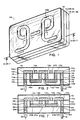
- FIGURE 1 is a perspective view of the completed luminous sign applicable to both the first and second embodiments.
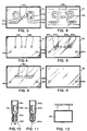
- FIGURE 2 is a cross-sectional side view of the completed luminous sign in the preferred embodiment.
- FIGURE 3 is a plan view of the upper side of the front transparent legend plate as used in both the preferred and second embodiments.
- FIGURE 4 is a plan view of the center feedthrough plate of the preferred embodiment.
- FIGURE 5 is a plan view of the upper side of the back crossover cavity plate of the preferred embodiment.
- FIGURE 6 is a plan view of the backside of FIGURE 3.
- FIGURE 7 is a cross-sectional side view of the completed luminous sign in the second embodiment.
- FIGURE 8 is a plan view of the upperside of the center crossover cavity/bore plate of the second embodiment.
- FIGURE 9 is a plan view of the back feedthrough plate of the second embodiment.
- FIGURE 10 is a cross-sectional side view of a typical tubulated electrode.
- FIGURE 11 is a cross-sectional side view of a typical non-tubulated electrode.
- FIGURE 12 is a representative block diagram of a power source.
- the preferred embodiment of the sign 10, as shown in FIGURES 1-6, is comprised of three major elements: a front transparent legend plate 12, a center feedthrough plate 14, a back crossover cavity plate 16, a tubulated electrode 18 and a non-tubulated electrode 20. To complete the sign's utility, an external power source 30 is also required.
- the front transparent plate 12 functions as the frontal plate from where the selected legend is viewed.
- the plate may be constructed of either plate glass or plastic.
- the legend 12a as shown in FIGURES 1 and 3, consists of a legend cavity that is formed from the backside of the plate 12.
- the cavity is formed by a cavity producing means which includes an etching process, sandblasting, grinding, a laser beam or any other cavity producing methods.
- the legend cavity may also be formed by molding or vacuum forming the front transparent legend plate over a mold incorporating the legend. This method is well known in the art and therefore is not described or shown in the drawings.
- Each segment of the legend must terminate at a legend crossover intersection 12b.
- a legend crossover intersection 12b For example, in the legend depicted in FIGURES 1 and 3, there are two crossover intersections 12b where each intersection includes two crossover points 12c.
- the center feedthrough plate 14 as shown in cross section in FIGURE 2 and in a plan view in FIGURE 4, provides the bores that allow a continuous (uninterrupted) gas flow to occur from the legend beginning end 12d, through each of the crossover intersections 12b and to the legend ending end 12e.
- This plate is sandwiched between the front transparent plate 12 and the back crossover cavity plate 16 that is described infra.
- the plate 14 has a termination bore 14a therethrough in alignment with the legend beginning end 12d and the legend ending end 12e.
- the final plate necessary to complete the first embodiment of the luminous sign 10 is the back crossover cavity plate 16 shown in cross section in FIGURE 2 and in an upper side plan view in FIGURE 5.
- This plate includes the input and output connections to the power source and includes on its top side the crossover cavities 16a that function with the crossover bores 14b to maintain gas continuity between the legend crossover intersections 12b.
- Each crossover cavity extends over the area encompassing each of the legend crossover intersections 12b located on the front transparent legend plate 12 and across the respective crossover bores 14b located on the center feedthrough plate 14.
- the back crossover cavity plate 16 also has a power/gas input bore 16b, 16c in concentric alignment with each of the respective termination bores 14a located on the center feedthrough plate 14.
- FIGURES 1, 3, 6, 7, 8 and 9 The second embodiment of the sign 10 is shown in FIGURES 1, 3, 6, 7, 8 and 9. This embodiment is also comprised of three major elements: a front transparent legend plate 12, a center crossover cavity/bore plate 24, a back feedthrough plate 26, a tubulated electrode 18, and a non-tubulated electrode 20. As with the first embodiment an external power source 30 is also needed.
- the front transparent legend plate 12 is dimensionally and functionally identical to that of the preferred embodiment, therefore no further description is required.
- the center crossover cavity/bore plate 24 shown in cross section in FIGURE 7 and in an upperside plan view in FIGURE 8, provides the bores and cavities that allow an uninterrupted gas flow from the legend beginning end 12d through each of the crossover intersections 12b, and to the legend ending end 12e.
- This plate is sandwiched between the front transparent legend plate 12 and the back feedthrough plate 26 described infra.
- the plate 24 has a termination bore 24a therethrough in alignment with the legend beginning end 12d and the legend ending end 12e.
- the plate also includes the crossover cavities 24b that are formed into its bottom side.
- the crossover cavities extend over the area encompassing each of the legend crossover intersections 12b located on the front transparent legend plate 12.
- Each crossover cavity 24b also has two crossover bores 24c where each bore, as best shown in FIGURE 7, is located within the cavity 24b at each end.
- the bores 24c extend upwardly and interface with the ends of the applicable legend crossover point 12c.
- the final plate necessary to complete the second embodiment of the luminous sign 10 is the back feed-through plate 26 shown in cross section in FIGURE 7 and in a plan view in FIGURE 9.
- This plate provides the input and output connection to the power source 30.
- the plate 26 is the least complex of all the other plates in that it only includes a set of power input bores 26a, 26b Each of the bores 26a, 26b are in concentric alignment with each of the respective termination bores 24a located on the center crossover cavity/bore plate 24.
- an opaque coating 12f of various legend contrasting colors may be applied to the legend back-ground area on the backside of the front transparent legend plate 12 as depicted in FIGURE 2.
- the coating 12f is preferably applied prior to forming the legend 12a.
- the coating is dissolved from the legend permitting light to be transmitted only through the legend 12a.
- the legend 12a may also be coated on its backside with a light transmissible, background contrasting coating or preferably with a color selectable phosphorescent chemical coating 12g as depicted in FIGURE 2.
- a plurality of different phosphorescent chemicals may be applied to the legend surface at selected intervals.
- the legend 12a will radiate in a plurality of colors.
- the phosphorescent chemical coating 12g it is important to avoid applications which are too thick as the chemical itself can block the passage of light from the ionized gas. Thicknesses ranging between .0014 to .0018 inches (35 to 40 microns) are considered best for maximum light emission.
- the luminous sign 10 To construct the luminous sign 10 several steps such as plate alignment, hermetic bonding, and gas insertion and encapsulation are required. Each of these manufacturing steps are next described and are applicable to the design as disclosed or to more complex designs where the legend is more complex and may be designed with several independent gas passages employing different gases and several electrodes.
- the alignment of the plates 12, 14, 16 or 12, 24 26 may be simply accomplished by accurately cutting two adjacent edges in each panel that serve as registration edges.
- the angular cut must be identical and at the same location for all three plates.
- Another method that may be employed is to affix to each plate in at least three corners a registration mark, such as a dot or cross.
- the legend image will be automatically aligned within each plate. After the alignment is verified, the required bores and cavities are formed and the plates are hermetically bonded.
- the hermetic bonding process is generally accomplished by using high temperature-sensitive adhesives 32 such as epoxies or silica containing sealants.
- high temperature-sensitive adhesives 32 such as epoxies or silica containing sealants.
- the type of adhesive used and the temperature needed depends on whether the plates are glass or plastic.
- the epoxies required for this purpose cure at temperatures between 200° to 350°F (93° to 177°C) over a curing period of from 2 to 16 hours depending on the epoxy used.
- the plates In addition to the heat, the plates must be cured under a compressive force to assure hermeticity.
- the force required is between 6 to 30 pounds per square inch (0.42 Kg/Cm 2 to 2.1 Kg/Cm 2 ) depending on the viscosity of the epoxy or sealant being used.
- the adhesive is generally applied over the entire surface of one of the contiguous plates or it may be applied selectively on one of the contiguous plates around the outside surface circumference of each of the bores 12a, 14b and 16b, 16c and around the outside perimeter of the legend 12a and crossover cavity 16a.
- the importance in either method used is to maintain hermeticity between the bores, cavities and inside plate perimeter.
- An additional bonding process that may be employed is to apply the selected adhesive to only the inside perimeter surface of the plates.
- it is especially critical to apply sufficient pressure to cause the plates to achieve a tight maximum surface contact.
- the use of this method does pose a problem; if the plate(s) has surface inconsistencies, the path of the gas may follow these inconsistencies, due to the lower resistance offered, and a short circuit may result.
- a very thin gasket 36 of insulation material may be placed on the top and bottom surface of the center plate 14, 24 as shown in FIGURE 7.
- the insulation material may be composed of a separate fine glass cloth that is laid on the plates or fine glass fibers or powder may be sprayed or deposited onto the plates by a deposition means.
- the important requirements of the material used is that it withstand the high compression and temperatures and that it outgas during the heating process to prevent contamination of the legend passages.
- the edges of the bores and cavities are better insulated to assure the required hermeticity.
- the insulative material may be placed on the plates prior to having the required bores or cavities on the plates drilled or sandblasted. Thus, when such drilling or sandblasting occurs the insulative material from the bores or channels is automatically removed.
- a tubulated electrode 18, as shown in FIGURES 2 and 7, is hermetically inserted into the first power/gas input bore 16b, 26a and a non-tubulated electrode 20 is hermetically inserted into the second power/gas input bore 16c, 26b.
- the electrodes 18, 20 have a diameter that allows a tight fit when inserted into the respective power/gas input bores.
- a hermetic seal 16d is easily accomplished by applying a fillet of epoxy or sealant around the circumference of the interface. The seal is then cured by using a conventional heating process.
- the tubulated electrode 18, as shown in FIGURE 10, is comprised of a primary glass tube 18a having within this tube a hermetically contained metallic electrode shell 18b connected to a set of electrical lead-in wires 18d that extend outside the glass tube 18a.
- Hermetically attached to the end of the primary glass tube 18a is a gas input tube 18c that provides a passage through the electrodes 18 into the legend passage way.
- the non-tubulated electrode 20, as shown in FIGURE 11, has no gas input tube and is only comprised of a primary glass tube 20a having hermetically encapsulated therein an electrode shell 20b having an electrical lead-in wire extending out from the end of the glass tube 20a.
- a tubulated electrode 18 that is, the gas input is separate from the electrical lead-in wire, then the gas is simply inserted through a small diameter glass gas tube (not shown) that is hermetically inserted into the legend gas passage way.
- the structure of the luminous sign 10 is complete.
- the ionizable gas may be introduced into the gas input tube 18c of the tubulated electrode 18.
- the gas input is commenced after the sign's temperature has been elevated to at least 450° F (232° C) while under a partial vacuum. If the gas is not inserted and a vacuum maintained while the plates are being cooled from the lamination and electrode insertion process, it will be necessary to reheat and re-evacuate the structure before gas is introduced.
- a vacuum is accomplished by connecting a vacuum pump (not shown) to the gas input tube 18c of the tubulated electrode or the optimal glass gas tube.
- the connection to the gas input tubes are not made directly from the vacuum pump but rather from the pump to a control manifold (not shown) then from the manifold to the gas input tubes.
- the manifold which is of a conventional type used in traditional neon shops, is comprised of glass tubes and vacuum tight stopcocks. When a vacuum pressure of approximately 15 microns is reached, the pump is isolated by means of a stopcock. The vacuum is applied at a temperature between 450 o F and 500 o F (232 o and 260 o C).
- the temperature should not drop below 450 o F (232 o C) because at these lower temperatures organic substances will not be drawn off by the partial vacuum and the structure will be contaminated. A contaminated structure will cause the neon not to glow or if it does glow the use life of the luminous sign 10 will be shortened.
- the vacuum is maintained until the structure is cooled to 150° F (66° C) or less at which time the neon gas or argon is introduced into the gas input tube 18c by opening another stopcock on the manifold that is connected to the source of neon or argon gas.
- the appropriate gas pressure is reached, as shown in TABLE II, the glass tube 18a of the tubulated electrode 18 is heated to a molten state causing the partial pressure within to draw the molten tube walls inward creating a hermetic seal.
- the completed luminous sign 10 is then removed from the manifold.
- the gas pressure of the gas introduced into the structure is dependent on the average cross sectional area of the bores and cavities within the plates 12, 14, 16 or 12, 24, 26. Assuming that the cross section is equal to that of a tube of a given diameter, then the pressures necessary are given in TABLE II. TABLE II Tube Diameter (Millimeters) Cross Section (Square Millimeters) Gas Pressures (Millimeters Mercury) 25 491 6 22 380 7 20 314 7.5 18 254 8 15 177 9 14 154 10 13 133 10 12 113 11 11 95 12 10 78 13 9 64 15 8 50 16 7 38 16.5 6 28 17.5 5 20 18.5 4 12.5 19.5 3 7 20.5 2 3 21.5
- the above pressures are for normal room temperature conditions. If the temperature is lower, the listed pressures may vary by several millimeters or up to 20 percent higher. If the temperature at which the gas is introduced is higher due to previous heating, an appropriate adjustment must be made in accordance to Boyle's Law covering pressure verus temperature.
- a power source 30 is connected across the electrical lead-in wire 18d and 20c located on the tubulated electrode 18 and non-tubulated electrode 20 respectively.
- the power source 30 is preferably an a-c power supply operating at 60Hz and rated to supply the required voltage and current to ionize the gas within the sign 10.
- a d-c power supply as well as high frequency power supplies may also be employed.
- a reservoir cavity 25 may be created as shown on the center channel/bore plate 24 of FIGURE 8. This cavity is not part of the legend circuit and may be located anywhere on the plate 24 as long as the cavity is not over any portion of the etched legend 12a.
- the cavity is connected, in this example, into the crossover channel 24b by means of a narrow feeder channel 25a as also shown in FIGURE 8.
- the reservoir cavity 25 serves to extend the operating life of the luminous sign by providing a reservoir of gas to replenish the gas that is depleted over a period of time. This gas loss can occur when the electrodes 18,20 sputter-off metal atoms which can entrap neon gas atoms against the wall of a channel. Additionally, the electrodes can absorb some of the gas and neon gas can be diffused into the walls of the structure.
- FIGURE 7 Another modification that may be made, is that in some legends (such a legend is not shown in the figures) it is possible to create a connecting channel that connects two ends of an etched legend in lieu of a crossover channel 24b as shown in FIGURE 7. In this design, the connecting channel is cut into the upper side of the center plate 24 with the two ends abutting the ends of the legend. Thus, eliminating the need for the crossover bores 24c and the crossover channel 24b as shown in FIGURE 7. Hence, the invention is described to cover any and all modifications and forms which may come within the language and scope of the claims.
Landscapes
- Physics & Mathematics (AREA)
- General Physics & Mathematics (AREA)
- Engineering & Computer Science (AREA)
- Theoretical Computer Science (AREA)
- Illuminated Signs And Luminous Advertising (AREA)
- Led Device Packages (AREA)
Claims (15)
- Eine Leuchtreklame bestehend aus:einer transparenten Vorderplatte (12) mit einer Legende (12a), die aus einem Legendenhohlraum besteht, welcher auf der Rückseite der Platte (12) geformt wird und über ein Anfangsbereich (12d) und ein Endbereich (12e) verfügt. Die Legende (12a) ist an den Schnittpunkten der Übergänge (12b) unterbrochen;einer mittleren Zufuhrplatte (14) hinter der transparenten Vorderplatte (12);einer Hinterplatte (16) hinter der mittleren Zufuhrplatte (14), die über eine erste (16b) und eine zweite Bohrung (16c) für die Strom-/ Gaszufuhr verfügt;Verfahren zur hermetischen Versiegelung (32) aller Platten (12, 24, 26) in der angegebenen Reihenfolge;Verfahren zum Zuführen (18, 18c) und hermetischen Einkapseln einer optimalen Menge an ionisierenden Gases in den Eingrenzungen des eingekapselten Legendenhohlraums; undVerfahren zum Aktivieren (18d, 20c) des ionisierenden Gases in der Art, daß es ein Leuchten der gesamten Legende (12a) erzeugt,wobeidie mittlere Zufuhrplatte eine durchgehende Ausgangsbohrung (14a) hat, die genau nach dem vorderen Endstück (12d) und dem hinteren Endstück (12e) der Legende (12a) ausgerichtet ist, sowie eine zusätzliche Übergangsbohrung (14b), die genau nach den Schnittpunkten der Übergänge (12b) ausgerichtet ist;die Hinterplatte hat einen Übergangshohlraum (16a) auf der Vorderseite, der sich über den ganzen alle Schnittpunkte an den Legendenübergängen (12b) der transparenten Vorderplatte (12) überspannenden Bereich ausstreckt sowie über die entsprechenden Bohrungen der Übergänge (14b) der mittleren Zufuhrplatte;jede Zufuhrbohrung (16b, 16c) auf der unteren Platte ist konzentrisch ausgerichtet nach der jeweiligen Ausgangsbohrung (14a) in der mittleren Zufuhrplatte (14);dies ist durch folgendes gekennzeichnet:ein Verfahren zur genauen Ausrichtung der drei Platten (12, 14, 16) in der angegebenen Reihenfolge; undein Verfahren zur hermetischen Versiegelung der drei Platten (12, 14, 16) das folgendes beinhaltet:(a) eine selektive Anwendung von temperaturempfindllichen Adhäsionsstoffen auf den sich berührenden Oberflächen jeder Platte,(b) eine genaue Ausrichtung der Platten,(c) eine Kompression der Platten durch ein Kompressionsverfahren, und(d) ein Erhärten der Platten unter Einwirkung von Druck und erhöhter Temperatur.
- Eine Leuchtreklame (10) bestehend aus:einer transparenten Vorderplatte (12) mit einer Legende (12a), die aus einem Legendenhohlraum besteht, der auf der Rückseite der Platte (12) geformt wird und über ein Anfangsbereich (12d) und ein Endbereich (12e) verfügt. Die Legende (12a) ist an den Schnittpunkten der Übergänge (12b) unterbrochen;einer mittleren Platte (24) hinter der transparenten Vorderplatte (12);eine hintere Zufuhrplatte (26) hinter der mittleren Platte (24), die über eine erste (26b) und eine zweite Bohrung (36b) für die Strom-/ Gaszufuhr verfügt;Verfahren zur hermetischem Versiegelung (32) aller Platten (12, 14, 16) in der angegebenen Reihenfolge;Verfahren zum Zuführen (18, 18c) und hermetischen Einkapseln einer optimalen Menge an ionisierenden Gases in den Eingrenzungen des eingekapselten Legendenhohlraums; undVerfahren zum Aktivieren (18d, 20c) des ionisierenden Gases in der Art, daß es ein Leuchten der gesamten Legende (12a) erzeugt;dies ist durch folgendes gekennzeichnet:die mittlere Platte (24) hat einen Übergangshohlraum (24b) auf ihrer Rückseite, der sich über den ganzen alle Schnittpunkte an den Legendenübergängen (12a) umfassenden Bereich ausstreckt, wobei jeder ausgehöhlter Übergang (24b) zwei Bohrungen (24c) hat, die an jedem Ende des Übergangshohlraums gelegen sind und sich nach oben hin entlang den Nahtstellen zu den Enden der entsprechenden Schnittpunkten der Legende ausdehnen. Ferner hat die mittlere Platte (24) auch Ausgangsbohrungen (24a), die genau nach dem Anfangsbereich (12d) und dem Endbereich (12e) der Legende (12a) ausgerichtet sind;jede Zufuhrbohrung (26a, 26b) auf der Rückseite der Zufuhrplatte ist konzentrisch nach der entsprechenden Bohrung für den Endkanal (24a) der mittleren Platte (24) ausgerichtet;Verfahren zur genauen Ausrichtung der drei Platten (12, 24, 26) in der angegebenen Reihenfolge.
- Die Leuchtreklame (10) gemäß Punkt 2 der Patentanmeldung ist dadurch gekennzeichnet, daß das Verfahren zur hermetischen Versiegelung aller drei Platten (12, 24, 26) folgendes beinhaltet:(a) selektive Anwendung eines temperaturempfindlichen Adhäsionsstoffes auf den sich berührenden Oberflächen der jeweiligen Platten,(b) genaues Ausrichten der Platten,(c) Kompression der Platten mit einem Kompressionsverfahren, und(d) Erhärten der Platten unter Einwirkung von Druck.
- Die Leuchtreklame (10) gemäß den Punkten 1, 2 oder 3 der Patentanmeldung ist dadurch gekennzeichnet, daß der Legendenhohlraum durch ein Verfahren zum Aushöhlen geformt wurde.
- Die Leuchtreklame (10) gemäß den Punkten 1, 2 oder 3 der Patentanmeldung ist dadurch gekennzeichnet, daß der Legendenhohlraum durch das Formen der transparenten Vorderplatte (12) mit der legende (12a) auf einer Form mit der entsprechenden Legende (12a) gebildet wurde.
- Die Leuchtreklame (10) gemäß den Punkten 1, 2 oder 3 der Patentanmeldung ist ferner durch eine opake Beschichtung (12f) gekennzeichnet, die auf den Hintergrund der Legende oder die Rückseite der transparenten Vorderplatte (12) aufgetragen wird. Die opake Beschichtung (12f) bewirkt, daß das Licht nur durch die Legende ausgestrahlt wird.
- Die Leuchtreklame (10) gemäß Punkt 5 der Patentanmeldung ist dadurch gekennzeichnet, daß der Hintergrund der Legende mit einer kontrastierenden Farbe (12g) beschichtet ist.
- Die Leuchtreklame (10) gemäß Punkt 5 der Patentanmeldung ist dadurch gekennzeichnet, daß die opake Beschichtung (12f) vor dem Formen des Legendenhohlraums aufgetragen wird.
- Die Leuchtreklame (10) gemäß den Punkten 1, 2 oder 3 der Patentanmeldung ist ferner durch eine nach freier Farbenwahl phosphoreszierende Chemikalie (12g) gekennzeichnet, die auf der Oberfläche des Legendehohlraums angewendet wird. Die phosphoreszierenden Chemikalien (12g) bewirken, daß die Legende (12g) nach freier Farbenwahl erleuchtet.
- Die Leuchtreklame (10) gemäß Punkt 8 der Patentanmeldung ist dadurch gekennzeichnet, daß die Mehrzahl der verschiedenen Chemikalien (12g) auf die Oberfläche des Legendenhohlraums in bestimmten Intervallen angewendet wird, so daß die Legende (12a) in einer Vielzahl von Farben erleuchtet.
- Die Leuchtreklame (10) gemäß den Punkten 1, 2 oder 3 der Patentanmeldung ist dadurch gekennzeichnet, daß das Verfahren zum genauen Ausrichten aller drei Platten (12, 14, 16; 12, 24, 26) folgendes beinhaltet: ein präzises Ausschneiden von zwei angrenzenden Kanten an den Platten (12, 14, 16; 12, 24, 26), die einen Winkel bilden, wobei die Kanten des Winkels als Bezugskanten dienen.
- Die Leuchtreklame (10) gemäß den Punkten 1, 2 oder 3 der Patentanmeldung ist dadurch gekennzeichnet, daß das Verfahren zur hermetischen Versiegelung (32) aller drei Platten (12, 14, 16; 12, 24, 26) folgendes beinhaltet: das Auftragen einer Dichtung (36) aus isolierendem Matcrial auf der Vorder- und Rückseite der mittleren Platte (14, 24).
- Die Leuchtreklame (10) gemäß den Punkten 1, 2 oder 3 der Patentanmeldung ist dadurch gekennzeichnet, daß das Verfahren zum Zuführen (18, 18c) und hermetischen Einkapseln einer optimalen Menge an ionisierenden Gases in den Eingrenzungen des eingekapselten Legendenhohlraums folgendes beinhaltet:(a) das Einfügen und hermetische Absiegeln der mit einer Zufuhrröhre versehenen Elektrode (18) in die erste Bohrung für die Strom-/ Gaszufuhr (16b, 26a),(b) das Einfügen und hermetische Absiegeln einer nicht mit einer Zufuhrröhre versehenen Elektrode (20) in die zweite Bohrung für die Strom-/Gaszufuhr (16c, 26b),(c) das Erzeugen und Beibehalten eines Vakuums in dem Bereich der Röhre der mit einer Röhre versehenen Elektrode (18), während die Leuchtreklame (10) bei einer erhöhten Temperatur bleibt,(d) das Einfügen des ionisierenden Gases durch den Röhrenabschnitt der mit einer Röhre versehenen Elektrode (18), und(e) die Erwärmung der Röhre bis zum Schmelzpunkt, um durch den partiellen Druck in der mit einer Röhre versehenen Elektrode (18) die geschmolzenen Wände der Röhre nach innen zu ziehen und sie dadurch zu versiegeln.
- Die Leuchtreklame (10) gemäß den Punkten 1, 2 oder 3 der Patentanmeldung ist dadurch gekennzeichnet, daß das Verfahren zum lonisieren des Gases die Anwendung elektrischen Sroms beinhaltet, der durch die beiden Elektroden (18, 20) führt.
- Die Leuchtreklame (10) gemäß den Punkten 1, 2 oder 3 der Patentanmeldung ist ferner durch einen Speicherhohlraum (25) in den Platten der Leuchtreklame (10) gekennzeichnet. Dieser Speicherhohlraum (25) befindet sich entfernt von der eingeprägten Legende (12a) und ist mit dem Kreislaufkanal über einen schmalen Zufuhrkanal verbunden.
Priority Applications (1)
| Application Number | Priority Date | Filing Date | Title |
|---|---|---|---|
| AT87908041T ATE143162T1 (de) | 1987-11-02 | 1987-11-02 | Lichtanzeige |
Applications Claiming Priority (1)
| Application Number | Priority Date | Filing Date | Title |
|---|---|---|---|
| PCT/US1987/002884 WO1989004531A1 (en) | 1987-11-02 | 1987-11-02 | Improved luminous sign |
Publications (3)
| Publication Number | Publication Date |
|---|---|
| EP0344155A1 EP0344155A1 (de) | 1989-12-06 |
| EP0344155A4 EP0344155A4 (en) | 1991-12-18 |
| EP0344155B1 true EP0344155B1 (de) | 1996-09-18 |
Family
ID=22202646
Family Applications (1)
| Application Number | Title | Priority Date | Filing Date |
|---|---|---|---|
| EP87908041A Expired - Lifetime EP0344155B1 (de) | 1987-11-02 | 1987-11-02 | Lichtanzeige |
Country Status (6)
| Country | Link |
|---|---|
| US (1) | US4703574A (de) |
| EP (1) | EP0344155B1 (de) |
| JP (1) | JP2860906B2 (de) |
| AU (1) | AU622609B2 (de) |
| DE (1) | DE3751911T2 (de) |
| WO (1) | WO1989004531A1 (de) |
Families Citing this family (20)
| Publication number | Priority date | Publication date | Assignee | Title |
|---|---|---|---|---|
| US4990826A (en) * | 1989-10-27 | 1991-02-05 | Cocks Franklin H | Low voltage gas discharge device |
| US5036243A (en) * | 1989-12-18 | 1991-07-30 | Cocks Franklin H | Glass plate illumination device sign with integral electrodes of particular thermal resistance |
| US5160566A (en) * | 1991-05-21 | 1992-11-03 | Ashby Michael L | Decorative glass block |
| US5321261A (en) * | 1992-09-10 | 1994-06-14 | Packard Instrument Company, Inc. | Normalization technique for photon-counting luminometer |
| US5383295A (en) * | 1992-12-21 | 1995-01-24 | Strattman; Wayne P. | Luminous display device |
| USD359311S (en) | 1993-06-21 | 1995-06-13 | Stangarone Nicholas G | Display sign |
| GB2281142A (en) * | 1993-08-05 | 1995-02-22 | Sean Robert Beech | Illuminated display arrangements |
| US5339230A (en) * | 1993-09-01 | 1994-08-16 | Devorris Philip E | Encapsulated charged gas light apparatus |
| WO1995034087A1 (en) * | 1994-06-06 | 1995-12-14 | Fallon Luminous Products Corporation | Gas discharge light |
| US5858046A (en) * | 1995-05-30 | 1999-01-12 | Corning Incorporated | Method of making an internally channeled glass article |
| US5744906A (en) * | 1995-12-22 | 1998-04-28 | Alford; Warren L. | Gas discharge illumination device |
| US5725299A (en) * | 1996-01-16 | 1998-03-10 | Devorris; Philip E. | Encapsulated charged gas lighting apparatus |
| US6452323B1 (en) | 1999-09-20 | 2002-09-17 | Omnion Technologies, Inc. | Luminous gas discharge display having dielectric sealing layer |
| US6512331B1 (en) * | 2000-11-09 | 2003-01-28 | Hing Hung Ricky Fu | Luminous display and method of making same |
| US6836072B2 (en) * | 2001-11-02 | 2004-12-28 | Electro Plasma, Inc. | Low voltage high efficiency illuminated display having capacitive coupled electrodes |
| KR100524084B1 (ko) * | 2004-02-27 | 2005-10-26 | 장덕연 | 팁이 없는 플라즈마 디스플레이 전광판, 이의 제조방법 및 제조장치 |
| USD557345S1 (en) * | 2006-11-07 | 2007-12-11 | Yates James P | Exit sign |
| US20120055055A1 (en) * | 2010-09-02 | 2012-03-08 | Illumin8 Outdoor Media, LLC | Systems and Method for Outdoor Media Signage |
| US10730343B2 (en) | 2016-12-01 | 2020-08-04 | John P. MACHUCA | Vehicle rim plasma display assembly, apparatus and insert |
| USD948159S1 (en) * | 2020-02-27 | 2022-04-05 | Kalalily Pty Ltd | Pet memorial urn |
Family Cites Families (11)
| Publication number | Priority date | Publication date | Assignee | Title |
|---|---|---|---|---|
| BE493924A (de) * | ||||
| US714233A (en) * | 1902-04-11 | 1902-11-25 | Emile Plancon | Sign illuminated by electric current. |
| US1743569A (en) * | 1927-11-16 | 1930-01-14 | William W Purdom | Method of making neon electric signs and neon signs |
| US1825399A (en) * | 1929-06-26 | 1931-09-29 | Hotchner Fred | Flat tubeless ionization conductor device |
| GB400646A (en) * | 1932-04-26 | 1933-10-26 | Reginald Pulford | Improvements in or relating to display signs or the like |
| US2158968A (en) * | 1938-06-01 | 1939-05-16 | Harvey C Wheeler | Incandescent gas sign and method of making same |
| US2644113A (en) * | 1950-05-22 | 1953-06-30 | Walter V Etzkorn | Luminous body |
| US2852877A (en) * | 1954-12-10 | 1958-09-23 | William A Goebel | Luminous sign |
| US3559190A (en) * | 1966-01-18 | 1971-01-26 | Univ Illinois | Gaseous display and memory apparatus |
| US3507065A (en) * | 1967-12-21 | 1970-04-21 | Technical Ordnance Inc | Overlay for illuminating tubing |
| US4584501A (en) * | 1984-06-27 | 1986-04-22 | Cocks Franklin H | Flat plate luminous display device |
-
1985
- 1985-12-03 US US06/804,183 patent/US4703574A/en not_active Expired - Lifetime
-
1987
- 1987-11-02 DE DE3751911T patent/DE3751911T2/de not_active Expired - Fee Related
- 1987-11-02 JP JP63500284A patent/JP2860906B2/ja not_active Expired - Lifetime
- 1987-11-02 EP EP87908041A patent/EP0344155B1/de not_active Expired - Lifetime
- 1987-11-02 WO PCT/US1987/002884 patent/WO1989004531A1/en not_active Ceased
- 1987-11-02 AU AU83315/87A patent/AU622609B2/en not_active Ceased
Also Published As
| Publication number | Publication date |
|---|---|
| EP0344155A1 (de) | 1989-12-06 |
| DE3751911T2 (de) | 1997-05-07 |
| US4703574A (en) | 1987-11-03 |
| EP0344155A4 (en) | 1991-12-18 |
| AU622609B2 (en) | 1992-04-16 |
| DE3751911D1 (de) | 1996-10-24 |
| JP2860906B2 (ja) | 1999-02-24 |
| JPH02502044A (ja) | 1990-07-05 |
| WO1989004531A1 (en) | 1989-05-18 |
| AU8331587A (en) | 1989-06-01 |
Similar Documents
| Publication | Publication Date | Title |
|---|---|---|
| EP0344155B1 (de) | Lichtanzeige | |
| CN100382224C (zh) | 气体放电屏及其制造方法 | |
| US6452323B1 (en) | Luminous gas discharge display having dielectric sealing layer | |
| US6313579B1 (en) | Plasma display panel with seal bonding member | |
| KR20000077347A (ko) | 플라즈마-패널 유형의 평면 디스플레이 스크린과 같은,접착되어야만 하는 유리 기판 상에서 구성소자를 제조하기위한 방법 | |
| KR100377066B1 (ko) | 플라즈마디스플레이와그제조방법 | |
| US20060091807A1 (en) | Flat lamp, production method thereof and application of same | |
| EP0052376B1 (de) | Gasentladungsanzeigetafel | |
| IT1261195B (it) | Foglio a trasferimento termico e metodo per formare uno schermo di fosfori impiegando il foglio a trasferimento termico. | |
| US3843427A (en) | Method of manufacturing a gas-discharge display panel | |
| US4195892A (en) | Batch production of plasma display panels | |
| JPH042030A (ja) | プラズマディスプレイパネルおよびその製造方法 | |
| US5270613A (en) | Two sided fluorescent indicator panel | |
| CA1276460C (en) | Luminous sign | |
| US6512331B1 (en) | Luminous display and method of making same | |
| US5911613A (en) | Luminous gas discharge display | |
| US4506261A (en) | Integrated gas discharge display panel | |
| WO1997029506A1 (en) | Thin-type display device | |
| KR100276115B1 (ko) | 전계 방출 표시 소자의 제어 전극 라인 형성 방법 | |
| ATE26192T1 (de) | Anzeigesystem und verfahren zur inbetriebnahme. | |
| KR100388122B1 (ko) | 교류구동형 플라즈마 대형 전광판의 제조방법 | |
| US6836072B2 (en) | Low voltage high efficiency illuminated display having capacitive coupled electrodes | |
| KR100252781B1 (ko) | 격자형스페이서를이용한전계방출표시소자의제조방법 | |
| JPH06302279A (ja) | フラットディスプレイパネル | |
| KR0163985B1 (ko) | 전계방출 소자의 진공실링 방법 |
Legal Events
| Date | Code | Title | Description |
|---|---|---|---|
| PUAI | Public reference made under article 153(3) epc to a published international application that has entered the european phase |
Free format text: ORIGINAL CODE: 0009012 |
|
| 17P | Request for examination filed |
Effective date: 19891004 |
|
| AK | Designated contracting states |
Kind code of ref document: A1 Designated state(s): AT BE CH DE FR GB IT LI LU NL SE |
|
| A4 | Supplementary search report drawn up and despatched |
Effective date: 19911029 |
|
| AK | Designated contracting states |
Kind code of ref document: A4 Designated state(s): AT BE CH DE FR GB IT LI LU NL SE |
|
| 17Q | First examination report despatched |
Effective date: 19930419 |
|
| GRAA | (expected) grant |
Free format text: ORIGINAL CODE: 0009210 |
|
| GRAH | Despatch of communication of intention to grant a patent |
Free format text: ORIGINAL CODE: EPIDOS IGRA |
|
| AK | Designated contracting states |
Kind code of ref document: B1 Designated state(s): AT BE CH DE FR GB IT LI LU NL SE |
|
| PG25 | Lapsed in a contracting state [announced via postgrant information from national office to epo] |
Ref country code: NL Free format text: LAPSE BECAUSE OF FAILURE TO SUBMIT A TRANSLATION OF THE DESCRIPTION OR TO PAY THE FEE WITHIN THE PRESCRIBED TIME-LIMIT Effective date: 19960918 Ref country code: LI Effective date: 19960918 Ref country code: CH Effective date: 19960918 Ref country code: BE Effective date: 19960918 Ref country code: AT Effective date: 19960918 |
|
| REF | Corresponds to: |
Ref document number: 143162 Country of ref document: AT Date of ref document: 19961015 Kind code of ref document: T |
|
| REF | Corresponds to: |
Ref document number: 3751911 Country of ref document: DE Date of ref document: 19961024 |
|
| PG25 | Lapsed in a contracting state [announced via postgrant information from national office to epo] |
Ref country code: LU Free format text: LAPSE BECAUSE OF NON-PAYMENT OF DUE FEES Effective date: 19961130 |
|
| ITF | It: translation for a ep patent filed | ||
| PG25 | Lapsed in a contracting state [announced via postgrant information from national office to epo] |
Ref country code: SE Effective date: 19961218 |
|
| ET | Fr: translation filed | ||
| NLV1 | Nl: lapsed or annulled due to failure to fulfill the requirements of art. 29p and 29m of the patents act | ||
| REG | Reference to a national code |
Ref country code: CH Ref legal event code: PL |
|
| PLBE | No opposition filed within time limit |
Free format text: ORIGINAL CODE: 0009261 |
|
| STAA | Information on the status of an ep patent application or granted ep patent |
Free format text: STATUS: NO OPPOSITION FILED WITHIN TIME LIMIT |
|
| 26N | No opposition filed | ||
| PGFP | Annual fee paid to national office [announced via postgrant information from national office to epo] |
Ref country code: FR Payment date: 19971210 Year of fee payment: 11 |
|
| PGFP | Annual fee paid to national office [announced via postgrant information from national office to epo] |
Ref country code: GB Payment date: 19971212 Year of fee payment: 11 |
|
| PGFP | Annual fee paid to national office [announced via postgrant information from national office to epo] |
Ref country code: DE Payment date: 19980113 Year of fee payment: 11 |
|
| PG25 | Lapsed in a contracting state [announced via postgrant information from national office to epo] |
Ref country code: GB Free format text: LAPSE BECAUSE OF NON-PAYMENT OF DUE FEES Effective date: 19981102 |
|
| GBPC | Gb: european patent ceased through non-payment of renewal fee |
Effective date: 19981102 |
|
| PG25 | Lapsed in a contracting state [announced via postgrant information from national office to epo] |
Ref country code: FR Free format text: LAPSE BECAUSE OF NON-PAYMENT OF DUE FEES Effective date: 19990730 |
|
| REG | Reference to a national code |
Ref country code: FR Ref legal event code: ST |
|
| PG25 | Lapsed in a contracting state [announced via postgrant information from national office to epo] |
Ref country code: DE Free format text: LAPSE BECAUSE OF NON-PAYMENT OF DUE FEES Effective date: 19990901 |
|
| PG25 | Lapsed in a contracting state [announced via postgrant information from national office to epo] |
Ref country code: IT Free format text: LAPSE BECAUSE OF NON-PAYMENT OF DUE FEES;WARNING: LAPSES OF ITALIAN PATENTS WITH EFFECTIVE DATE BEFORE 2007 MAY HAVE OCCURRED AT ANY TIME BEFORE 2007. THE CORRECT EFFECTIVE DATE MAY BE DIFFERENT FROM THE ONE RECORDED. Effective date: 20051102 |