EP0344330A1 - Procede de correction d'un profil de contour - Google Patents
Procede de correction d'un profil de contour Download PDFInfo
- Publication number
- EP0344330A1 EP0344330A1 EP89900322A EP89900322A EP0344330A1 EP 0344330 A1 EP0344330 A1 EP 0344330A1 EP 89900322 A EP89900322 A EP 89900322A EP 89900322 A EP89900322 A EP 89900322A EP 0344330 A1 EP0344330 A1 EP 0344330A1
- Authority
- EP
- European Patent Office
- Prior art keywords
- profile
- corner
- shape
- corner shape
- error
- Prior art date
- Legal status (The legal status is an assumption and is not a legal conclusion. Google has not performed a legal analysis and makes no representation as to the accuracy of the status listed.)
- Withdrawn
Links
Images


Classifications
-
- G—PHYSICS
- G05—CONTROLLING; REGULATING
- G05B—CONTROL OR REGULATING SYSTEMS IN GENERAL; FUNCTIONAL ELEMENTS OF SUCH SYSTEMS; MONITORING OR TESTING ARRANGEMENTS FOR SUCH SYSTEMS OR ELEMENTS
- G05B19/00—Program-control systems
- G05B19/02—Program-control systems electric
- G05B19/18—Numerical control [NC], i.e. automatically operating machines, in particular machine tools, e.g. in a manufacturing environment, so as to execute positioning, movement or co-ordinated operations by means of program data in numerical form
- G05B19/4093—Numerical control [NC], i.e. automatically operating machines, in particular machine tools, e.g. in a manufacturing environment, so as to execute positioning, movement or co-ordinated operations by means of program data in numerical form characterised by part programming, e.g. entry of geometrical information as taken from a technical drawing, combining this with machining and material information to obtain control information, named part program, for the NC machine
- G05B19/40931—Numerical control [NC], i.e. automatically operating machines, in particular machine tools, e.g. in a manufacturing environment, so as to execute positioning, movement or co-ordinated operations by means of program data in numerical form characterised by part programming, e.g. entry of geometrical information as taken from a technical drawing, combining this with machining and material information to obtain control information, named part program, for the NC machine concerning programming of geometry
- G05B19/40932—Shape input
- G05B19/40933—Selecting figure elements from a menu table
-
- G—PHYSICS
- G05—CONTROLLING; REGULATING
- G05B—CONTROL OR REGULATING SYSTEMS IN GENERAL; FUNCTIONAL ELEMENTS OF SUCH SYSTEMS; MONITORING OR TESTING ARRANGEMENTS FOR SUCH SYSTEMS OR ELEMENTS
- G05B2219/00—Program-control systems
- G05B2219/30—Nc systems
- G05B2219/36—Nc in input of data, input key till input tape
- G05B2219/36077—Display and select, modify shape, pattern on screen
-
- G—PHYSICS
- G05—CONTROLLING; REGULATING
- G05B—CONTROL OR REGULATING SYSTEMS IN GENERAL; FUNCTIONAL ELEMENTS OF SUCH SYSTEMS; MONITORING OR TESTING ARRANGEMENTS FOR SUCH SYSTEMS OR ELEMENTS
- G05B2219/00—Program-control systems
- G05B2219/30—Nc systems
- G05B2219/36—Nc in input of data, input key till input tape
- G05B2219/36221—Entry of chamfer, beveling, rounding of corner shape
-
- G—PHYSICS
- G05—CONTROLLING; REGULATING
- G05B—CONTROL OR REGULATING SYSTEMS IN GENERAL; FUNCTIONAL ELEMENTS OF SUCH SYSTEMS; MONITORING OR TESTING ARRANGEMENTS FOR SUCH SYSTEMS OR ELEMENTS
- G05B2219/00—Program-control systems
- G05B2219/30—Nc systems
- G05B2219/36—Nc in input of data, input key till input tape
- G05B2219/36313—If elements cannot be combined, show error
-
- G—PHYSICS
- G05—CONTROLLING; REGULATING
- G05B—CONTROL OR REGULATING SYSTEMS IN GENERAL; FUNCTIONAL ELEMENTS OF SUCH SYSTEMS; MONITORING OR TESTING ARRANGEMENTS FOR SUCH SYSTEMS OR ELEMENTS
- G05B2219/00—Program-control systems
- G05B2219/30—Nc systems
- G05B2219/36—Nc in input of data, input key till input tape
- G05B2219/36325—Enter shape with mouse, tablet, enter on screen coordinates, lines, circles
-
- Y—GENERAL TAGGING OF NEW TECHNOLOGICAL DEVELOPMENTS; GENERAL TAGGING OF CROSS-SECTIONAL TECHNOLOGIES SPANNING OVER SEVERAL SECTIONS OF THE IPC; TECHNICAL SUBJECTS COVERED BY FORMER USPC CROSS-REFERENCE ART COLLECTIONS [XRACs] AND DIGESTS
- Y02—TECHNOLOGIES OR APPLICATIONS FOR MITIGATION OR ADAPTATION AGAINST CLIMATE CHANGE
- Y02P—CLIMATE CHANGE MITIGATION TECHNOLOGIES IN THE PRODUCTION OR PROCESSING OF GOODS
- Y02P90/00—Enabling technologies with a potential contribution to greenhouse gas [GHG] emissions mitigation
- Y02P90/02—Total factory control, e.g. smart factories, flexible manufacturing systems [FMS] or integrated manufacturing systems [IMS]
Definitions
- This invention relates to a method of revising a profile generated using figure definition statements in an automatic programming language, and more particularly, to a profile revising method for revising an already defined profile and for suitably revising a corner shape such as a chamfered or rounded shape contained in the profile.
- the already defined figure elements are arrayed in order along the profile.
- rR r represents the radius
- cC c represents the amount of chamfer
- revision screen and an execution screen displaying the profile are separate screens in the prior art. Therefore, when an error occurs, a revision must be carried out by switching back and forth between the execution screen and the revision screen. This is a troublesome task.
- an object of the present invention is to provide a profile revising method in which revision of a profile can be executed without being aware of the presence of chamfered or rounded corner shapes, in which the location of an error can be clarified when an error occurs due to a revision, and in which revision of a profile and display of the profile can be performed on the same screen.
- the present invention provides a profile revising method for revising a profile in which a corner shape such as a chamfered shape or rounded shape (circular arc) or the like has been inserted.
- a figure element other than those of corner shapes is revised and the revised profile, which does not include the corner shapes, is displayed. Thereafter, if an error is generated when: the corner shapes are inserted in the revised profile one at a time, the dimensions of the corner portion at which the error occurred are displayed on a display screen to make revision possible. Also, the corner shape at which the error occurred is displayed in a color different from that of the other portions of the profile. By revising the corner shape at which the error occurred, the revised corner shape is inserted in the new profile, which is displayed.
- Fig. 1 is a block diagram of an apparatus for practicing the present invention.
- Numeral 101 denotes a ROM storing a loading program and the like, 102 a processor for executing automatic programming processing, and 103 a RAM for storing a system program read in from a floppy FL, as well as various parameters and results of processing.
- Numeral 104 denotes an NC data memory for storing the finally created NC data having an executable format, 105 a keyboard, 106 a display unit (CRT), 107 a disc controller, and 108 a tablet device having a tablet surface 108a to which a menu chart 108b having menu items is affixed. Prescribed menu items are picked by a tablet cursor 108c.
- FL represents a floppy disc.
- Fig. 2 is a view for describing the principal parts of the menu chart 108b.
- Numeral 1 is a "POINT/POINT GROUP DEFINITION” section, 2 a “STRAIGHT LINE DEFINITION” section, 3 a “CIRCLE DEFINITION” section, 4 a "SPECIAL SHAPE DEFINITION” section and 5 a “SHAPE MODIFICATION” section.
- the "SHAPE MODIFICATION” section 5 is provided with an "ELEMENT REVISION" section 5a indicating an item for revising a figure element.
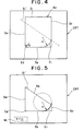
- a 0 appearing on the CRT 106 represents a profile, prior to revision, composed of the already defined figure elements S 1 - 8 4 .
- a O ' represents the profile after the figure element S 1 is revised to S 1 ' in profile A 0 .
- E 1 , E 2 represent corner shapes having rounded configurations (circular arcs), and M 1 denotes a message.
- the processor 102 causes the revised profile A 0 ', which does not include the corner shapes E l , E 2 , to be displayed on the CRT, and subsequently inserts the corner shapes E 1 , E 2 into the revised profile A O ' in order one at a time. If an error is generated at this time, or in other words, if it becomes impossible to insert a corner shape, the message M 1 relating to the dimensions of the corner shape (e.g., E 1 ) at which the error has occurred is displayed on the display screen CRT to make revision possible, and the corner shape at which the error has occurred is painted in a color different from that of the other portions of the profile. By revising the corner shape E 1 at which the error occurred, the revised corner shape is inserted in the new profile A 0 ', which is displayed.
- Fig. 3 is a flowchart of profile revising processing according to the invention
- Figs. 4 through 8 are views for describing the profile revising processing of the invention. The method of the present invention will now be described in accordance with these Figures.
- a system program, parameters and the like for forming an NC part program have already been stored in the RAM 103 from the floppy disk FL.
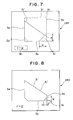
- the straight-line elements S 1 - S 4 shown in Fig. 4 are defined using the tablet device 108 and keyboard 105 (step 201), then rounding of radii r 1 , r 2 is inserted to define the profile A 0 (step 202).
- the definition statements of the profile are as follows, just as described in relation to Fig. 10:
- the processor 102 causes the revised profile (which does not include the rounded or chamfered corner shape) A O ' inclusive of the revised straight line S 1 ' to be displayed on the CRT 106 (step 207 1 see Fig. 5).
- the first corner shape E 1 which is a circular arc of radius r 1 , is inserted at the original location, namely between the line segments S 1 and S 2 .
- the processor 102 causes the circular arc of the corner shape E 1 to be displayed in a color (or bold line) different from the color of the other portions of the profile, as shown in Fig. 5, and causes the message M i having the arc dimension r 1 of the corner shape E 1 to be displayed (steps 210, 211).
- the corner shape is inserted in the profile and displayed (step 212).
- the operator manipulates the keyboard 105 to key in the new arc radius r 1 ' (step 213).
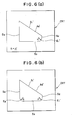
- the processor 102 inserts the circular arc (corner shape E 1 ') of radius r l ' between the straight lines S 1 , S 2 , and causes the shape to be displayed in the same color as the other portions of the profile [step 214; see Fig. 6(a)].
- the program jumps to step 208.
- the processor 102 repeats the processing from step 209 onward. Since the other corner shape E 2 is present in the example, the processor inserts the corner shape, namely the circular arc of radius r 2 , between the straight lines S 3 , S 4 , which is the original location [step 209; see Fig. 6(b)]. In this case, the circular arc contacts the two sides S 31 S 4 simultaneously. Therefore, no error is generated (step 210) and the profile having the inserted circular arc is displayed. Thereafter, the foregoing processing is repeated until all corner shapes are inserted. When insertion of all corner shapes is completed, a "NO" answer is received at step S208, so that profile revision processing is terminated. In the example, the profile definition statements are revised to the following:
- the chamfer amount c of the chamfered shape is greater than the length of one of the line segments forming the corner at which the chamfer shape is inserted, insertion of the chamfered shape is impossible and an error is produced.
- the present invention is applicable also in cases where arcuate and chamfered shapes are mixed as the corner shapes.
- the arrangement is such that a figure element other than those of corner shapes is revised and the revised profile, which does not include the corner shapes, is displayed. Thereafter, if insertion becomes impossible and an error is generated when the corner shapes are inserted in the revised profile one at a time, the dimensions of the corner portion at which the error occurred are displayed on a display screen to make revision possible. Also, the corner shape at which the error occurred is displayed in a color" different from that of the other portions of the profile. By revising the corner shape at which the error occurred, the revised corner shape is inserted in the new profile, which is displayed.
- revision of a profile can be executed without one being aware of the presence of chamfered or rounded corner shapes, the location of an error can be clarified automatically even when an error occurs, and revision of a profile and display of the profile can be performed on the same screen. This makes it possible to facilitate the revision operation.
Landscapes
- Engineering & Computer Science (AREA)
- Human Computer Interaction (AREA)
- Physics & Mathematics (AREA)
- Geometry (AREA)
- Manufacturing & Machinery (AREA)
- General Physics & Mathematics (AREA)
- Automation & Control Theory (AREA)
- Numerical Control (AREA)
- Processing Of Color Television Signals (AREA)
Abstract
Lorsqu'on corrige un élément de profil (S1) d'un profil de contour (A0) tracé sur un écran cathodique (106) de manière à obtenir un élément de profil (S1'), un processeur (102) décrit sur l'écran du terminal un profil de contour corrigé (A0') qui ne contient de profils d'angle (E1, E2). Ces profils d'angle (E1, E2) sont ensuite corrigés un à un et introduits dans le profil de contour (A0'). Si une erreur se produit à ce moment, ou s'il devient impossible d'introduire les profils d'angle, une question (M1) relative à la taille du profil d'angle (E1) à l'origine de l'erreur est affichée à l'écran du terminal afin de permettre d'effectuer la correction. En outre, le profil d'angle (E1) à l'origine de l'erreur est tracé avec une couleur différente de celle des autres parties de contour. Le profil d'angle (E1) à l'origine de l'erreur est corrigé, introduit dans un nouveau profil de contour (A0') et visualisé.
Applications Claiming Priority (2)
| Application Number | Priority Date | Filing Date | Title |
|---|---|---|---|
| JP319389/87 | 1987-12-17 | ||
| JP62319389A JP2579330B2 (ja) | 1987-12-17 | 1987-12-17 | 輪郭形状修正方法 |
Publications (2)
| Publication Number | Publication Date |
|---|---|
| EP0344330A1 true EP0344330A1 (fr) | 1989-12-06 |
| EP0344330A4 EP0344330A4 (en) | 1993-07-21 |
Family
ID=18109621
Family Applications (1)
| Application Number | Title | Priority Date | Filing Date |
|---|---|---|---|
| EP19890900322 Withdrawn EP0344330A4 (en) | 1987-12-17 | 1988-12-13 | Method of correcting contour profile |
Country Status (4)
| Country | Link |
|---|---|
| US (1) | US5063517A (fr) |
| EP (1) | EP0344330A4 (fr) |
| JP (1) | JP2579330B2 (fr) |
| WO (1) | WO1989006005A1 (fr) |
Families Citing this family (5)
| Publication number | Priority date | Publication date | Assignee | Title |
|---|---|---|---|---|
| JP2753364B2 (ja) * | 1990-02-23 | 1998-05-20 | オークマ株式会社 | 数値制御情報作成装置 |
| EP0524934B1 (fr) * | 1991-02-20 | 1997-06-04 | A.G. für industrielle Elektronik AGIE Losone bei Locarno | Dispositif pour la surveillance et le sequencement des fonctions d'une machine d'etincelage |
| JP2773517B2 (ja) * | 1992-02-27 | 1998-07-09 | 三菱電機株式会社 | プログラム表示装置 |
| CN102789197B (zh) * | 2011-05-19 | 2016-06-22 | 科德数控股份有限公司 | 数控机床加工信息的表达系统及其表达方法 |
| CN112648949B (zh) * | 2020-12-04 | 2024-06-21 | 成都宏明双新科技股份有限公司 | 一种打弯件产品外轮廓尺寸快速修正装置 |
Family Cites Families (9)
| Publication number | Priority date | Publication date | Assignee | Title |
|---|---|---|---|---|
| JPS60191365A (ja) * | 1984-03-13 | 1985-09-28 | Okuma Mach Works Ltd | 自動プログラミング機能における形状入力方式 |
| JPS61251964A (ja) * | 1985-04-30 | 1986-11-08 | Toshiba Corp | 図形変更装置 |
| JPS62121511A (ja) * | 1985-11-22 | 1987-06-02 | Mitsubishi Electric Corp | 数値制御装置 |
| JPS63104104A (ja) * | 1986-10-21 | 1988-05-09 | Fanuc Ltd | 自動プログラミングシステム |
| JPH07111646B2 (ja) * | 1987-02-20 | 1995-11-29 | フアナツク株式会社 | 部品形状入力方法 |
| JPS63244109A (ja) * | 1987-03-30 | 1988-10-11 | Fanuc Ltd | 自動プログラミングシステム |
| JPS63250707A (ja) * | 1987-04-07 | 1988-10-18 | Fanuc Ltd | 部品形状入力方法 |
| JPS6468807A (en) * | 1987-09-10 | 1989-03-14 | Fanuc Ltd | Outline shape correcting method |
| JP3419872B2 (ja) * | 1993-02-19 | 2003-06-23 | ヤマハ発動機株式会社 | エンジンの吸気装置 |
-
1987
- 1987-12-17 JP JP62319389A patent/JP2579330B2/ja not_active Expired - Lifetime
-
1988
- 1988-12-13 EP EP19890900322 patent/EP0344330A4/en not_active Withdrawn
- 1988-12-13 WO PCT/JP1988/001261 patent/WO1989006005A1/fr not_active Ceased
- 1988-12-13 US US07/397,453 patent/US5063517A/en not_active Expired - Fee Related
Also Published As
| Publication number | Publication date |
|---|---|
| JP2579330B2 (ja) | 1997-02-05 |
| EP0344330A4 (en) | 1993-07-21 |
| US5063517A (en) | 1991-11-05 |
| WO1989006005A1 (fr) | 1989-06-29 |
| JPH01159706A (ja) | 1989-06-22 |
Similar Documents
| Publication | Publication Date | Title |
|---|---|---|
| US4926311A (en) | Part profile input method | |
| EP0177164B1 (fr) | Méthode et appareil pour la production des programmes pour la commande numérique | |
| US5729750A (en) | Automatic dimensioning in computer aided design | |
| EP0348522B1 (fr) | Procede d'introduction des donnees relatives au profil d'une piece | |
| US4901220A (en) | Part profile input method | |
| EP0355166A1 (fr) | Procede de correction d'elements d'image | |
| EP0344330A1 (fr) | Procede de correction d'un profil de contour | |
| EP0348533B1 (fr) | Procede de programmation automatique | |
| US5021966A (en) | Profile revising method | |
| US5469189A (en) | Display apparatus and method with multi-window function | |
| EP0349650A1 (fr) | Procede de definition d'un profil combine | |
| EP0356524A1 (fr) | Procede de preparation d'un programme de partie pour des formes similaires | |
| US5043865A (en) | Profile revising method | |
| EP0336978B1 (fr) | Procede de correction d'un profil de contour | |
| EP0148948A1 (fr) | Procede permettant de fixer les valeurs des donnees dans un appareil de commande numerique | |
| EP0378696A1 (fr) | Procede de definition de profil/forme | |
| EP0342240B1 (fr) | Procede de correction d'un element d'image | |
| EP0383940A1 (fr) | Procede d'introduction des donnees relatives a la forme d'un coin | |
| EP0336975A1 (fr) | Procede de preparation de donnees de commande numerique | |
| EP0372086A1 (fr) | Procede d'etablissement du format de sortie de donnees de commande numerique | |
| EP0383938A1 (fr) | Systeme d'introduction de donnees relatives a la forme d'une piece | |
| US5093796A (en) | Automatic programming definition of a machining configuration for a numerical control device | |
| EP0332703A1 (fr) | Systeme d'introduction de donnees | |
| JPH01166205A (ja) | 輪郭プログラム修正方法 | |
| JP3615230B2 (ja) | Cadシステム |
Legal Events
| Date | Code | Title | Description |
|---|---|---|---|
| PUAI | Public reference made under article 153(3) epc to a published international application that has entered the european phase |
Free format text: ORIGINAL CODE: 0009012 |
|
| 17P | Request for examination filed |
Effective date: 19890831 |
|
| AK | Designated contracting states |
Kind code of ref document: A1 Designated state(s): DE FR GB IT |
|
| RHK1 | Main classification (correction) |
Ipc: G05B 19/405 |
|
| A4 | Supplementary search report drawn up and despatched |
Effective date: 19930528 |
|
| AK | Designated contracting states |
Kind code of ref document: A4 Designated state(s): DE FR GB IT |
|
| STAA | Information on the status of an ep patent application or granted ep patent |
Free format text: STATUS: THE APPLICATION IS DEEMED TO BE WITHDRAWN |
|
| 18D | Application deemed to be withdrawn |
Effective date: 19930701 |