EP0344356A1 - Appareil pour le soudage de feuilles en matière plastique - Google Patents
Appareil pour le soudage de feuilles en matière plastique Download PDFInfo
- Publication number
- EP0344356A1 EP0344356A1 EP19880112748 EP88112748A EP0344356A1 EP 0344356 A1 EP0344356 A1 EP 0344356A1 EP 19880112748 EP19880112748 EP 19880112748 EP 88112748 A EP88112748 A EP 88112748A EP 0344356 A1 EP0344356 A1 EP 0344356A1
- Authority
- EP
- European Patent Office
- Prior art keywords
- welding
- clamps
- foils
- rod
- welding rod
- Prior art date
- Legal status (The legal status is an assumption and is not a legal conclusion. Google has not performed a legal analysis and makes no representation as to the accuracy of the status listed.)
- Withdrawn
Links
Images

Classifications
-
- B—PERFORMING OPERATIONS; TRANSPORTING
- B29—WORKING OF PLASTICS; WORKING OF SUBSTANCES IN A PLASTIC STATE IN GENERAL
- B29C—SHAPING OR JOINING OF PLASTICS; SHAPING OF MATERIAL IN A PLASTIC STATE, NOT OTHERWISE PROVIDED FOR; AFTER-TREATMENT OF THE SHAPED PRODUCTS, e.g. REPAIRING
- B29C65/00—Joining or sealing of preformed parts, e.g. welding of plastics materials; Apparatus therefor
- B29C65/02—Joining or sealing of preformed parts, e.g. welding of plastics materials; Apparatus therefor by heating, with or without pressure
- B29C65/18—Joining or sealing of preformed parts, e.g. welding of plastics materials; Apparatus therefor by heating, with or without pressure using heated tools
-
- B—PERFORMING OPERATIONS; TRANSPORTING
- B29—WORKING OF PLASTICS; WORKING OF SUBSTANCES IN A PLASTIC STATE IN GENERAL
- B29C—SHAPING OR JOINING OF PLASTICS; SHAPING OF MATERIAL IN A PLASTIC STATE, NOT OTHERWISE PROVIDED FOR; AFTER-TREATMENT OF THE SHAPED PRODUCTS, e.g. REPAIRING
- B29C65/00—Joining or sealing of preformed parts, e.g. welding of plastics materials; Apparatus therefor
- B29C65/74—Joining or sealing of preformed parts, e.g. welding of plastics materials; Apparatus therefor by welding and severing, or by joining and severing, the severing being performed in the area to be joined, next to the area to be joined, in the joint area or next to the joint area
- B29C65/743—Joining or sealing of preformed parts, e.g. welding of plastics materials; Apparatus therefor by welding and severing, or by joining and severing, the severing being performed in the area to be joined, next to the area to be joined, in the joint area or next to the joint area using the same tool for both joining and severing, said tool being monobloc or formed by several parts mounted together and forming a monobloc
-
- B—PERFORMING OPERATIONS; TRANSPORTING
- B29—WORKING OF PLASTICS; WORKING OF SUBSTANCES IN A PLASTIC STATE IN GENERAL
- B29C—SHAPING OR JOINING OF PLASTICS; SHAPING OF MATERIAL IN A PLASTIC STATE, NOT OTHERWISE PROVIDED FOR; AFTER-TREATMENT OF THE SHAPED PRODUCTS, e.g. REPAIRING
- B29C66/00—General aspects of processes or apparatus for joining preformed parts
- B29C66/01—General aspects dealing with the joint area or with the area to be joined
- B29C66/05—Particular design of joint configurations
- B29C66/10—Particular design of joint configurations particular design of the joint cross-sections
- B29C66/11—Joint cross-sections comprising a single joint-segment, i.e. one of the parts to be joined comprising a single joint-segment in the joint cross-section
- B29C66/112—Single lapped joints
- B29C66/1122—Single lap to lap joints, i.e. overlap joints
-
- B—PERFORMING OPERATIONS; TRANSPORTING
- B29—WORKING OF PLASTICS; WORKING OF SUBSTANCES IN A PLASTIC STATE IN GENERAL
- B29C—SHAPING OR JOINING OF PLASTICS; SHAPING OF MATERIAL IN A PLASTIC STATE, NOT OTHERWISE PROVIDED FOR; AFTER-TREATMENT OF THE SHAPED PRODUCTS, e.g. REPAIRING
- B29C66/00—General aspects of processes or apparatus for joining preformed parts
- B29C66/01—General aspects dealing with the joint area or with the area to be joined
- B29C66/343—Making tension-free or wrinkle-free joints
- B29C66/3432—Making tension-free or wrinkle-free joints by holding the material loose or tension-free during joining
-
- B—PERFORMING OPERATIONS; TRANSPORTING
- B29—WORKING OF PLASTICS; WORKING OF SUBSTANCES IN A PLASTIC STATE IN GENERAL
- B29C—SHAPING OR JOINING OF PLASTICS; SHAPING OF MATERIAL IN A PLASTIC STATE, NOT OTHERWISE PROVIDED FOR; AFTER-TREATMENT OF THE SHAPED PRODUCTS, e.g. REPAIRING
- B29C66/00—General aspects of processes or apparatus for joining preformed parts
- B29C66/40—General aspects of joining substantially flat articles, e.g. plates, sheets or web-like materials; Making flat seams in tubular or hollow articles; Joining single elements to substantially flat surfaces
- B29C66/41—Joining substantially flat articles ; Making flat seams in tubular or hollow articles
- B29C66/43—Joining a relatively small portion of the surface of said articles
- B29C66/431—Joining the articles to themselves
- B29C66/4312—Joining the articles to themselves for making flat seams in tubular or hollow articles, e.g. transversal seams
-
- B—PERFORMING OPERATIONS; TRANSPORTING
- B29—WORKING OF PLASTICS; WORKING OF SUBSTANCES IN A PLASTIC STATE IN GENERAL
- B29C—SHAPING OR JOINING OF PLASTICS; SHAPING OF MATERIAL IN A PLASTIC STATE, NOT OTHERWISE PROVIDED FOR; AFTER-TREATMENT OF THE SHAPED PRODUCTS, e.g. REPAIRING
- B29C66/00—General aspects of processes or apparatus for joining preformed parts
- B29C66/80—General aspects of machine operations or constructions and parts thereof
-
- B—PERFORMING OPERATIONS; TRANSPORTING
- B29—WORKING OF PLASTICS; WORKING OF SUBSTANCES IN A PLASTIC STATE IN GENERAL
- B29C—SHAPING OR JOINING OF PLASTICS; SHAPING OF MATERIAL IN A PLASTIC STATE, NOT OTHERWISE PROVIDED FOR; AFTER-TREATMENT OF THE SHAPED PRODUCTS, e.g. REPAIRING
- B29C66/00—General aspects of processes or apparatus for joining preformed parts
- B29C66/80—General aspects of machine operations or constructions and parts thereof
- B29C66/81—General aspects of the pressing elements, i.e. the elements applying pressure on the parts to be joined in the area to be joined, e.g. the welding jaws or clamps
- B29C66/814—General aspects of the pressing elements, i.e. the elements applying pressure on the parts to be joined in the area to be joined, e.g. the welding jaws or clamps characterised by the design of the pressing elements, e.g. of the welding jaws or clamps
- B29C66/8141—General aspects of the pressing elements, i.e. the elements applying pressure on the parts to be joined in the area to be joined, e.g. the welding jaws or clamps characterised by the design of the pressing elements, e.g. of the welding jaws or clamps characterised by the surface geometry of the part of the pressing elements, e.g. welding jaws or clamps, coming into contact with the parts to be joined
- B29C66/81411—General aspects of the pressing elements, i.e. the elements applying pressure on the parts to be joined in the area to be joined, e.g. the welding jaws or clamps characterised by the design of the pressing elements, e.g. of the welding jaws or clamps characterised by the surface geometry of the part of the pressing elements, e.g. welding jaws or clamps, coming into contact with the parts to be joined characterised by its cross-section, e.g. transversal or longitudinal, being non-flat
- B29C66/81415—General aspects of the pressing elements, i.e. the elements applying pressure on the parts to be joined in the area to be joined, e.g. the welding jaws or clamps characterised by the design of the pressing elements, e.g. of the welding jaws or clamps characterised by the surface geometry of the part of the pressing elements, e.g. welding jaws or clamps, coming into contact with the parts to be joined characterised by its cross-section, e.g. transversal or longitudinal, being non-flat being bevelled
- B29C66/81417—General aspects of the pressing elements, i.e. the elements applying pressure on the parts to be joined in the area to be joined, e.g. the welding jaws or clamps characterised by the design of the pressing elements, e.g. of the welding jaws or clamps characterised by the surface geometry of the part of the pressing elements, e.g. welding jaws or clamps, coming into contact with the parts to be joined characterised by its cross-section, e.g. transversal or longitudinal, being non-flat being bevelled being V-shaped
-
- B—PERFORMING OPERATIONS; TRANSPORTING
- B29—WORKING OF PLASTICS; WORKING OF SUBSTANCES IN A PLASTIC STATE IN GENERAL
- B29C—SHAPING OR JOINING OF PLASTICS; SHAPING OF MATERIAL IN A PLASTIC STATE, NOT OTHERWISE PROVIDED FOR; AFTER-TREATMENT OF THE SHAPED PRODUCTS, e.g. REPAIRING
- B29C66/00—General aspects of processes or apparatus for joining preformed parts
- B29C66/80—General aspects of machine operations or constructions and parts thereof
- B29C66/81—General aspects of the pressing elements, i.e. the elements applying pressure on the parts to be joined in the area to be joined, e.g. the welding jaws or clamps
- B29C66/814—General aspects of the pressing elements, i.e. the elements applying pressure on the parts to be joined in the area to be joined, e.g. the welding jaws or clamps characterised by the design of the pressing elements, e.g. of the welding jaws or clamps
- B29C66/8141—General aspects of the pressing elements, i.e. the elements applying pressure on the parts to be joined in the area to be joined, e.g. the welding jaws or clamps characterised by the design of the pressing elements, e.g. of the welding jaws or clamps characterised by the surface geometry of the part of the pressing elements, e.g. welding jaws or clamps, coming into contact with the parts to be joined
- B29C66/81427—General aspects of the pressing elements, i.e. the elements applying pressure on the parts to be joined in the area to be joined, e.g. the welding jaws or clamps characterised by the design of the pressing elements, e.g. of the welding jaws or clamps characterised by the surface geometry of the part of the pressing elements, e.g. welding jaws or clamps, coming into contact with the parts to be joined comprising a single ridge, e.g. for making a weakening line; comprising a single tooth
-
- B—PERFORMING OPERATIONS; TRANSPORTING
- B29—WORKING OF PLASTICS; WORKING OF SUBSTANCES IN A PLASTIC STATE IN GENERAL
- B29C—SHAPING OR JOINING OF PLASTICS; SHAPING OF MATERIAL IN A PLASTIC STATE, NOT OTHERWISE PROVIDED FOR; AFTER-TREATMENT OF THE SHAPED PRODUCTS, e.g. REPAIRING
- B29C66/00—General aspects of processes or apparatus for joining preformed parts
- B29C66/80—General aspects of machine operations or constructions and parts thereof
- B29C66/81—General aspects of the pressing elements, i.e. the elements applying pressure on the parts to be joined in the area to be joined, e.g. the welding jaws or clamps
- B29C66/816—General aspects of the pressing elements, i.e. the elements applying pressure on the parts to be joined in the area to be joined, e.g. the welding jaws or clamps characterised by the mounting of the pressing elements, e.g. of the welding jaws or clamps
- B29C66/8161—General aspects of the pressing elements, i.e. the elements applying pressure on the parts to be joined in the area to be joined, e.g. the welding jaws or clamps characterised by the mounting of the pressing elements, e.g. of the welding jaws or clamps said pressing elements being supported or backed-up by springs or by resilient material
-
- B—PERFORMING OPERATIONS; TRANSPORTING
- B29—WORKING OF PLASTICS; WORKING OF SUBSTANCES IN A PLASTIC STATE IN GENERAL
- B29C—SHAPING OR JOINING OF PLASTICS; SHAPING OF MATERIAL IN A PLASTIC STATE, NOT OTHERWISE PROVIDED FOR; AFTER-TREATMENT OF THE SHAPED PRODUCTS, e.g. REPAIRING
- B29C66/00—General aspects of processes or apparatus for joining preformed parts
- B29C66/80—General aspects of machine operations or constructions and parts thereof
- B29C66/83—General aspects of machine operations or constructions and parts thereof characterised by the movement of the joining or pressing tools
- B29C66/832—Reciprocating joining or pressing tools
- B29C66/8322—Joining or pressing tools reciprocating along one axis
- B29C66/83221—Joining or pressing tools reciprocating along one axis cooperating reciprocating tools, each tool reciprocating along one axis
-
- B—PERFORMING OPERATIONS; TRANSPORTING
- B29—WORKING OF PLASTICS; WORKING OF SUBSTANCES IN A PLASTIC STATE IN GENERAL
- B29C—SHAPING OR JOINING OF PLASTICS; SHAPING OF MATERIAL IN A PLASTIC STATE, NOT OTHERWISE PROVIDED FOR; AFTER-TREATMENT OF THE SHAPED PRODUCTS, e.g. REPAIRING
- B29C66/00—General aspects of processes or apparatus for joining preformed parts
- B29C66/80—General aspects of machine operations or constructions and parts thereof
- B29C66/84—Specific machine types or machines suitable for specific applications
- B29C66/849—Packaging machines
Definitions
- the invention relates to a device for welding, in particular for the separation welding of foils, which loop around one or more objects under tension, with two mutually movable pairs of clamps, between which a heated welding rod and a welding pad are movably arranged, such that the films between the pairs of clamps the clamping process and before the welding process are bulged against the welding rod, and the welding process takes place after the welding base has been moved back with substantially relieved foils.
- a device of the type specified above has become known from DE-OS 19 03 515.
- objects are enveloped by a film which are pushed against a film curtain, the two film parts of the curtain being connected to one another behind the objects by welding, specifically by means of separation welding.
- the objects are covered with a loop made of a plastic film.
- the created container is separated and at the same time a new foil curtain is formed for the subsequent wrapping process.
- this foil tension must be taken into account when welding or separating welding.
- both the welding base and the welding rod are driven in such a way that the welding rod is first advanced so that the foils to be welded together are bulged against the welding rod after clamping. After the clamping process, the welding pad is pulled back, the foils being relaxed. The welding then takes place.
- DE-OS 23 65 953 describes a banding machine which has a special tightening device in order to tighten the film after wrapping it but before welding.
- the foils to be welded and separated are held by only two pairs of clamps. Although the film is stretched tight, there is no special device to relieve the film during welding. This makes the construction considerably easier.
- the separation welds can no longer be achieved with simple means.
- the device of the aforementioned DE-OS 19 03 515 is not or is difficult to use.
- the problem is that this known device has a complicated structure and requires a plurality of drive means not only to move the clamps and the welding rod, but also to bring about the necessary movement of the welding pad.
- Container With the problem of subdividing objects encased together into smaller ones Container also has the problem that the position of the device in the machine must be changeable. The width of the individual containers has to be changed frequently, and accordingly the separating welding devices have to be moved laterally to the conveying direction.
- the invention is therefore based on the object of providing a device with which it is possible to achieve useful results when welding, in particular when welding foils separately, even when the foils have a considerable tension, and in particular the device is of simple design and therefore should have small dimensions, so that it is possible to use the device even in confined spaces.
- the invention is based on a device of the type specified at the outset and proposes that the welding pad is under the action of an elastic feed force which is large enough to bulge the foils, and the welding rod being the welding pad at the start of the welding process pushes back.
- the welding pad is under the action of an elastic feed force which can easily be dimensioned in the desired manner. In this way, a special drive of the welding pad can be saved.
- the welding pad is only to be arranged between the corresponding clamps and ensures that the film section between the clamps is bulged like a roof during the clamping process. After the clamping process, the foils are still under considerable tension. However, if the welding rod is pushed forward, it presses against the foils and thus against the welding pad, which can withdraw a corresponding amount. A special drive for the welding pad is not necessary.
- the retreat occurs so quickly that the weld has not yet weakened the foils so that the foils are torn apart.
- the welding process only takes place when the foils are already relieved.
- the welding process in particular the separation welding process, then takes place in the usual way.
- the clamps are released and the tension of the film parts outside the clamps also affects the area of the weld. The weld is then no longer destroyed because it has already cooled down sufficiently.
- the invention achieves a very simple construction. Only the clamps and the welding rod have to be driven. Films can also be processed at extreme tensions, and in particular it is possible to use the arrangement according to the invention even in very confined spaces. In particular, it is possible to accommodate, for example, a plurality of such devices, for dividing a film loop formed together into a number of individual containers.
- the two clamps are connected to one another and driven together on one side of the film, and that these two clamps have a guide and a holder for the welding pad between them. It is particularly provided that the two clamps on the side of the welding rod are interconnected and driven together.
- the invention proposes that the two clamps on the other side of the film are interconnected and driven together, and that the two clamps have a guide for the welding rod between them. It is beneficial if the clamps and the welding rod have one thing in common have the same drive and the terminals can be pressed back against the action of a spring or the like.
- This design significantly simplifies the device according to the invention.
- the welding pad with the associated clamps is moved against the foils and, simultaneously or immediately afterwards, the welding rod with the associated clamps also moves against the foils.
- the elastic means ensure that the foils are first pretensioned roof-like from the welding pad, that the two foils are subsequently clamped, and that the welding rod finally pushes back the welding pad and carries out the welding process.
- the device according to the invention can be used with particular advantage when it comes to subdividing the separate containers so far that these containers are still partially attached to one another.
- Such a partial separation welding in the manner of a perforation has the advantage that the removal of the finished containers is considerably simplified.
- the invention proposes that the heated welding rod has a plurality of notches which form interruption points in the separation welding, at which the parts to be separated are attached to one another.
- the formation of coherent structures in the aforementioned manner succeeds in the invention in particular because the welding of the plastic films takes place in the unloaded state, the risk of the welding tearing is practically eliminated.
- the device according to the invention is shown in a section.
- the section plane or the image plane corresponds to the plane of the film curtain through which the objects 3 have been pushed and have been enveloped by the films 1, 2.
- Slides 1, 2 consist of a weldable plastic.
- the foils 1, 2 can be a single piece of foil. But in particular they can also consist of two parts.
- the foils 1, 2 can also encase a large number of individual objects together.
- the objects 3 in the illustration of the drawing have a cylindrical shape. It can be cans or the like.
- the bracket 23 is supported by the support 24 on the drive 22, which is represented by a rod.
- the devices for moving this rod or the drive 22 are not shown in detail.
- the support plate 25 on the support 24 forms an abutment for the spring 26.
- These springs 26 act on the lower ends of the clamps 6 and 7, so that these clamps 6 and 7 are taken along when the drive 22 is lifted, as is the welding rod 8. However, if the terminals 6 and 7 encounter resistance, they can remain behind due to the springs 26 with respect to the feed movement of the drive 26.
- the welding pad 9 is arranged above the objects 3, which are enveloped by the foils 1 and 2, and can be moved by means of the drive 29, which is shown as a rod is.
- the welding pad 9 is seated in a recess 14 in the holder 12, which is supported by a spring 10 on an abutment 27 of the drive 29.
- the spring 10 surrounds a rod 28 which can dip into the abutment 27.
- the bracket 12 is movable in the guide 11 which is arranged on the inside of the terminals 4 and 5.
- the terminals 4 and 5 are rigidly connected to the drive 29.
- the front of the terminals 4 and 5 carries an elastic insert or a support 13 to improve the hold of the film during the clamping process.
- the drive 29 is moved downwards and the drive 22 upwards. Both movements can take place simultaneously, but it is also possible to delay the lifting movement of the drive 22 somewhat.
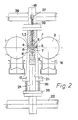
- 2 shows the position of the drives 29 and 22 in which the terminal 4 interacts with the terminal 6, while the terminals 5 and 7 also clamp the foils 1, 2.
- the welding pad 9 is already pushed back somewhat against the action of the spring 10 because of the tensioned foils 1 and 2, and the holder 12 has been pushed back somewhat into the guide 11.
- the welding pad 9 protrudes clearly above the terminals 4, 5, so that the foils 1, 2 are bulged downwards.
- FIG. 2 The position of FIG. 2 is only of short duration or only a transition stage.
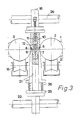
- the hot welding rod 8 presses the welding pad 9 against the force of the spring 10 further back, so that the film part, which runs between the pairs of terminals 4 and 6 or 5 and 7, is relaxed.
- This position is shown in FIG. 3. It is clear that with this further advance of the drive 22, the springs 26 are compressed further, since a further advance of the terminals 6 and 7 is not possible.
- the foil parts 1, 2 are welded separately between the gills 4 and 6 on the one hand and 5 and 7 on the other hand. After the separation welding process and adequate cooling, the clamping can be released again.
- the welding rod 8 is formed uniformly over its entire length, there is a complete separation welding.
- the foils 1, 2 are cut through in the plane 18 but are also welded to one another at the same time. In special cases, welding alone can be used. After the clamps have been loosened, the foils 1, 2 lie practically completely against the objects.
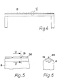
- FIGS. 4 to 6 When a welding rod 8 is used, as shown in FIGS. 4 to 6, there is a partial separation welding.
- the notches 15 arranged at a uniform distance on the welding rod 8 interrupt the separation welding, so that the individual containers are still connected at these points.
- the welding rod 8 has a roof-like formation 19 with a knife-like welding edge 20 on its working side.
- the welding edge 20 essentially comes into contact only with the foils 1, 2 and also presses back the welding base 9.
Landscapes
- Engineering & Computer Science (AREA)
- Mechanical Engineering (AREA)
- Package Closures (AREA)
- Basic Packing Technique (AREA)
Applications Claiming Priority (2)
| Application Number | Priority Date | Filing Date | Title |
|---|---|---|---|
| DE3818664 | 1988-06-01 | ||
| DE19883818664 DE3818664A1 (de) | 1988-06-01 | 1988-06-01 | Vorrichtung zum verschweissen von kunststoffolien |
Publications (1)
| Publication Number | Publication Date |
|---|---|
| EP0344356A1 true EP0344356A1 (fr) | 1989-12-06 |
Family
ID=6355627
Family Applications (1)
| Application Number | Title | Priority Date | Filing Date |
|---|---|---|---|
| EP19880112748 Withdrawn EP0344356A1 (fr) | 1988-06-01 | 1988-08-05 | Appareil pour le soudage de feuilles en matière plastique |
Country Status (2)
| Country | Link |
|---|---|
| EP (1) | EP0344356A1 (fr) |
| DE (1) | DE3818664A1 (fr) |
Cited By (1)
| Publication number | Priority date | Publication date | Assignee | Title |
|---|---|---|---|---|
| EP0568534A4 (en) * | 1990-11-09 | 1993-12-01 | Weldotron Of Delaware, Inc. | Heat sealing method and apparatus |
Families Citing this family (2)
| Publication number | Priority date | Publication date | Assignee | Title |
|---|---|---|---|---|
| DE4233878A1 (de) * | 1992-10-08 | 1994-04-14 | Texpa Arbter Maschbau Gmbh | Vorrichtung zum Schweißen und Trennen thermisch verschweißbarer Einfaßbänder aus Kunststoff mit textilem Charakter |
| DE19732703C2 (de) * | 1997-07-30 | 2001-11-22 | Tetra Laval Holdings & Finance | Siegelbacke |
Citations (5)
| Publication number | Priority date | Publication date | Assignee | Title |
|---|---|---|---|---|
| US3075573A (en) * | 1959-09-23 | 1963-01-29 | Continental Can Co | Apparatus for punching holes or cutouts in thermoplastic sheet material |
| FR1397917A (fr) * | 1963-04-12 | 1965-05-07 | Weldotron Corp | Appareil et procédé pour la formation de paquets avec une matière d'emballage soudable à chaud |
| GB1090575A (en) * | 1965-03-16 | 1967-11-08 | Ici Ltd | Heat sealing plastic film |
| DE1903515A1 (de) * | 1968-02-19 | 1969-09-18 | Weldotron Corp | Verfahren und Vorrichtung zum Herstellen einer eng anliegenden Huelse aus plastischem Film rings um einen Gegenstand |
| DE1479549B1 (de) * | 1963-11-30 | 1970-10-22 | Maschinenbau Aachen-Fürstenau GmbH, 5100 Aachen | Trennschweißvorrichtung |
-
1988
- 1988-06-01 DE DE19883818664 patent/DE3818664A1/de not_active Withdrawn
- 1988-08-05 EP EP19880112748 patent/EP0344356A1/fr not_active Withdrawn
Patent Citations (5)
| Publication number | Priority date | Publication date | Assignee | Title |
|---|---|---|---|---|
| US3075573A (en) * | 1959-09-23 | 1963-01-29 | Continental Can Co | Apparatus for punching holes or cutouts in thermoplastic sheet material |
| FR1397917A (fr) * | 1963-04-12 | 1965-05-07 | Weldotron Corp | Appareil et procédé pour la formation de paquets avec une matière d'emballage soudable à chaud |
| DE1479549B1 (de) * | 1963-11-30 | 1970-10-22 | Maschinenbau Aachen-Fürstenau GmbH, 5100 Aachen | Trennschweißvorrichtung |
| GB1090575A (en) * | 1965-03-16 | 1967-11-08 | Ici Ltd | Heat sealing plastic film |
| DE1903515A1 (de) * | 1968-02-19 | 1969-09-18 | Weldotron Corp | Verfahren und Vorrichtung zum Herstellen einer eng anliegenden Huelse aus plastischem Film rings um einen Gegenstand |
Cited By (1)
| Publication number | Priority date | Publication date | Assignee | Title |
|---|---|---|---|---|
| EP0568534A4 (en) * | 1990-11-09 | 1993-12-01 | Weldotron Of Delaware, Inc. | Heat sealing method and apparatus |
Also Published As
| Publication number | Publication date |
|---|---|
| DE3818664A1 (de) | 1989-08-03 |
Similar Documents
| Publication | Publication Date | Title |
|---|---|---|
| DE1461915C3 (de) | Vorrichtung zur Herstellung von Quaderpackungen | |
| DE2521474C3 (de) | Spann- und Reibungsschweißvorrichtung für ein einen Gegenstand umschlingendes Band aus thermoplastischem Kunststoff | |
| DE1561966A1 (de) | Verfahren und Vorrichtung zum Verpacken von Waren | |
| DE69820886T2 (de) | Entdrahtungsanlage | |
| DE2751118C2 (de) | Trennschweißvorrichtung für bahnenweise vorgeschobene, aufeinanderliegende Folien | |
| DE2200419C3 (de) | Vorrichtung zur intermittierenden Zufuhr eines Abschnitts einer Folienbahn aus einer Vorratsrolle zum Verschließen eines Behälters | |
| EP0178457B1 (fr) | Dispositif pour le liage de matériaux bobinés | |
| DE2515338A1 (de) | Vorrichtung zur befestigung von kunststoffgriffen an einem beutelschlauch | |
| DE1805322B2 (de) | Bindemaschine | |
| DE3130121C2 (de) | Vorrichtung zum Anbringen von oberen Begrenzungsteilen an einem Reißverschlußband | |
| EP3613676B1 (fr) | Machine d'emballage dotée d'un dispositif de coupe à consommation d'énergie optimisée | |
| DE2051779A1 (de) | Bandschneide und schweißvor richtung | |
| EP0344356A1 (fr) | Appareil pour le soudage de feuilles en matière plastique | |
| DE3248574C2 (de) | Querschneider zum Durchtrennen von Folienbahnen z.B. in Verpackungsmaschinen | |
| EP0001121A2 (fr) | Dispositif de banderolage d'un paquet de feuilles non serré tel que billets de banque ou similaires | |
| DE1479312A1 (de) | Maschine zur Ausfuehrung von Applikationen und Arbeiten im Innern eines schlauchfoermigen,durchgehenden Werkstueckes aus thermoplastischem od.dgl. Material | |
| DE2619422C2 (de) | Folienverpackungsmaschine | |
| WO2016008764A1 (fr) | Procédé et dispositif de production de paquets cerclés | |
| EP1050459A2 (fr) | Procédé et dispositif pour envelopper un objet avec une feuille thermoplastique | |
| DE1082564B (de) | Vorrichtung zum Herstellen von gliedfreien Stellen bei Verschlussstreifen von aus fortlaufenden Windungen bestehenden Reissverschluessen | |
| DE2824381A1 (de) | Verfahren und vorrichtung zum buendeln, banderolieren oder verpacken von packgut | |
| AT356585B (de) | Vorrichtung zum buendeln von stanzteilen und etiketten | |
| DE2609189A1 (de) | Vorrichtung zum umschnueren eines paketes oder dergleichen mit einem kunststoff-band | |
| DE2560465C2 (fr) | ||
| DE1586100A1 (de) | Schweissvorrichtung an einer Maschine zum Herstellen von Kettenpackungen aus thermoplastischen Packstoffen |
Legal Events
| Date | Code | Title | Description |
|---|---|---|---|
| PUAI | Public reference made under article 153(3) epc to a published international application that has entered the european phase |
Free format text: ORIGINAL CODE: 0009012 |
|
| AK | Designated contracting states |
Kind code of ref document: A1 Designated state(s): AT BE CH DE ES FR GB GR IT LI LU NL SE |
|
| STAA | Information on the status of an ep patent application or granted ep patent |
Free format text: STATUS: THE APPLICATION IS DEEMED TO BE WITHDRAWN |
|
| 18D | Application deemed to be withdrawn |
Effective date: 19900607 |