EP0344506A2 - Pince en fil d'acier à ressort - Google Patents
Pince en fil d'acier à ressort Download PDFInfo
- Publication number
- EP0344506A2 EP0344506A2 EP89108713A EP89108713A EP0344506A2 EP 0344506 A2 EP0344506 A2 EP 0344506A2 EP 89108713 A EP89108713 A EP 89108713A EP 89108713 A EP89108713 A EP 89108713A EP 0344506 A2 EP0344506 A2 EP 0344506A2
- Authority
- EP
- European Patent Office
- Prior art keywords
- jaw
- gripping
- pair
- article
- spring
- Prior art date
- Legal status (The legal status is an assumption and is not a legal conclusion. Google has not performed a legal analysis and makes no representation as to the accuracy of the status listed.)
- Withdrawn
Links
Images


Classifications
-
- B—PERFORMING OPERATIONS; TRANSPORTING
- B65—CONVEYING; PACKING; STORING; HANDLING THIN OR FILAMENTARY MATERIAL
- B65H—HANDLING THIN OR FILAMENTARY MATERIAL, e.g. SHEETS, WEBS, CABLES
- B65H29/00—Delivering or advancing articles from machines; Advancing articles to or into piles
- B65H29/003—Delivering or advancing articles from machines; Advancing articles to or into piles by grippers
Definitions
- the present invention relates to a gripper jaw for use in a gripper assembly which is operable between an open position and a closed position to grip an article therein.
- Gripper assemblies incorporating gripper jaws are commonly used in conveyor assemblies to convey sheet material articles, such as newspapers or magazines, from one location to another.
- U.S. Patent 4,638,906 shows a conveyor assembly which includes a plurality of gripper assemblies connected by a conveyor chain. Such a conveyor assembly is shown in U.S. Patent 4,721,296 incorporated into a sheet material handling apparatus, which includes a plurality of pockets for forming sheet material assemblages such as newspapers. The conveyor assembly extends beneath the pockets. A completed sheet material assemblage drops out of a pocket into an open gripper assembly on the conveyor. The gripper assembly then closes about and clamps the sheet material assemblage for transport elsewhere by the conveyor.
- U.S. Patent 4,681,213 shows a movable gripper jaw which is pivotable relative to a stationary gripper jaw.
- the movable gripper jaw has a flat spring steel configuration.
- Another gripper assembly is shown in U.S. Patent 4,320,894 and includes lower and upper gripper jaws.
- the upper gripper jaw has a pair of pivotable clamping members which are, independently of one another, pivotable about the shaft upon which they are mounted.
- the clamping members are spring-biased to a closed position against the lower gripper jaw by a torsion spring mounted on the shaft.
- a new and improved gripper jaw for gripping an article such as a folded newspaper.
- the gripper jaw is made of spring wire and has a pair of gripping tangs to clamp the article against a fixed gripper jaw.
- the spring wire gripper jaw has a pair of torsion springs associated one with each gripping tang to bias the gripping tangs against the article.
- the gripping tangs are able to flex and grip independently of each other, to compensate for thickness variations in the article.
- the spring wire gripper jaw also includes a pressing element which extends between and interconnects the gripping tangs.
- the pressing element presses against the article at its lower edge to provide additional gripping force. If the article is, for example, a folded newspaper, the pressing element forces air out of the folded edge of the newspaper.
- the present invention is described herein as being used in a conveyor assembly for conveying sheet material articles such as folded newspapers. It is to be understood, however, that a gripper jaw or gripper assembly as described herein may be useful in other environments, and accordingly the present invention is not limited to use solely in the described environment.
- Fig. 1 illustrates a conveyor assembly 10 which includes a plurality of gripper assemblies 12 each incorporating a gripper jaw 30 in accordance with the present invention.
- the gripper assemblies 12 are connected to each other by a continuous conveyor chain 14.
- the conveyor chain 14 is movable in the direction of arrow 15 along a track 16.
- the track 16 extends from a pick-up station (not shown) to a delivery station (not shown) and then back to the pick-up station.
- Each gripper assembly 12 is connected to a link 18 in the conveyor chain 14, and is used to grip articles to be transported between the pick-up and delivery stations.
- Only three links 18 of the conveyor chain 14 are shown in Fig. 1, it should be understood that a relatively large number of identical links 18 are interconnected to form a continuous conveyor chain 14.
- Each gripper assembly 12 (Fig. 1 and 5) includes a stationary jaw 20 secured to a gripper base block 22, and a movable jaw 30 pivotally mounted on the base block 22.
- the gripper assembly 12 is operable between an open position and a closed position to grip an article therein.
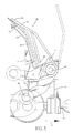
- Fig. 5 illustrates the gripper assembly 12 in its normally closed position, clamping an article 26 (shown in phantom) such as a newspaper.
- the movable jaw 30 is pivoted away from the fixed jaw 20, in a clockwise direction as viewed in Fig. 5.
- the movable jaw 30 is pivoted back toward the fixed jaw 20 to clamp the article 26.
- Such operation will be described in more detail hereafter.
- Figs. 2 and 3 illustrate in detail the gripper jaw 30.
- the jaw 30 is formed from wire, and preferably comprises a single continuous piece of spring wire or the equivalent thereof such as two or more pieces of wire joined together to act as one.
- the jaw 30 is formed from stainless steel spring wire to minimize corrosion.
- the jaw 30 includes a pair of torsion springs 40 and 42, a pair of gripping tangs 44 and 46, and a pressing element 48.
- the upper portion 50 (about one inch or so) of gripping tang 44, and the corresponding upper portion 52 of gripping tang 46, may be coated with a material such as plastic (not shown) in order to provide a gripping surface which is more suitable for the article being gripped than, for example, bare stainless steel.
- the gripping tangs 44 and 46 can flex independently of each other (in the direction toward or away from the viewer in Fig. 2) in order to securely clamp an article 26 which may be of uneven thickness.
- the pressing element 48 can move independently of the gripping tangs 44 and 46. For example, as best seen in Fig. 3, the pressing element 48 may press the lower (folded) edge of a newspaper 26 deposited in a gripper assembly 12. The pressing element 48 thus provides an extra gripping location in addition to gripping tangs 44 and 46. It also helps to force the air out of the folded edge of the newspaper.
- Fig. 4 illustrates in detail the structure of the gripper assembly 12 which incorporates the gripper jaw 30.
- the gripper base block 22 is fixed to a chain link 18, with a track shield 24 interposed therebetween.
- Each chain link 18, as part of conveyor the chain 14, rides within track 16.
- the base block 22 will be pulled along track 16 also.
- the base block 22 has a shaft 60 rotatably received in a bore 62 therein.
- the shaft 60 is longer than the base block 22 and extends outwardly of the base block 22 at both ends.
- a pair of actuator arms 34 and 35 are secured at either end of the shaft 60.
- a hollow cylindrical spacer 64 is disposed about the shaft 60 between one end 66 of the base block 22 and the actuator arm 34.
- the actuator arm 34 is secured to shaft 60, with its inner side 68 abutting the spacer 64, by a roll pin 70.
- a hollow cyclindrical spacer 72 is disposed between the opposite outer end 74 of the base block 22 and the actuator arm 35.
- the actuator arm 35 is secured to shaft 60, with its inner side 76 disposed adjacent spacer 72, by a roll pin 78.
- the actuator arm 34 and 35 carry cam roller wheels 32 and 33, respectively.
- Cam roller wheel 32 is journalled on a shaft 80 which is fixed to arm 34.
- a bushing 82 is disposed between cam roller wheel 32 and actuator arm 34.
- cam roller wheel 33 is journalled on a shaft 81 which is fixed to arm 35.
- a bushing 83 is disposed between cam roller wheel 33 and actuator arm 35.
- the gripper jaw 30 (Fig. 4) is mounted for pivotal movement in the gripper assembly 12 by torsion springs 40 and 42.
- Torsion spring 40 circumscribes the outer end portion 90 of the base block 22, the spacer 64, and the inner portion 68 of actuator arm 34.
- An end portion 54 of the torsion spring 40 is anchored in a bore 94 in the base block 22.
- the torsion spring 42 circumscribes the outer portion 92 of the base block 22, the spacer 72, and the inner portion 76 of actuator arm 35.
- An end portion 56 of the torsion spring 42 is anchored in a bore 96 in the base block 22.
- the torsion springs 40 and 42 are wound up so that the gripping tangs 44 and 46 are biased toward the fixed jaw 20, that is, in a counterclockwise direction as seen in Figs. 1 and 5.
- the bias exerted by torsion springs 40 and 42 normally maintains the movable jaw 30 against the fixed jaw 20, and so the gripper assembly 12 is normally in a closed position. In such position, the torsional force exerted by the torsion springs 40 and 42 is strong enough to securely clamp an article 26, such as a newspaper, between the movable jaw 30 and the fixed jaw 20.
- the actuator arms 34 and 35 (Figs. 4 and 5), which move the jaw 30 from its normally closed position to its open position, are biased into engagement with the movable jaw 30.
- a first actuator spring 100 biases actuator arm 34 against jaw 30, through gripping tang 44.
- the actuator spring 100 is located within an annular axially extending bore 102 between the shaft 60 and the spacer 64.
- One end 104 of the actuator spring 100 is anchored in a bore 106 in the actuator arm 34, the other end 108 in a bore 110 in the base block 22.
- a roll pin 111 is press fitted in the end of actuator arm 34 adjacent to a portion of the gripping tang 44.
- the actuator spring 100 is wound up so that it exerts a torsional force between the base block 22 and the actuator arm 34 in a direction (clockwise as seen in Fig. 5) as to urge actuator arm 34 and thus roll pin 111 against gripping tang 44.
- actuator arm 34 is constantly biased into engagement with the gripping tang 44 and will move therewith.
- a second actuator spring 112 biases the actuator arm 35 against the gripping tang 46.
- the actuator spring 112 is located within an annular, axially extending bore 114 between the shaft 60 and the spacer 72.
- One end 116 of torsion spring 112 is anchored in a bore 118 in the base block 22, the other end in a bore 122 in the actuator arm 35.
- a roll pin 124 is press fitted in actuator arm 35 adjacent the gripping tang 46.
- the actuator spring 112 is wound up so that it exerts a torsional force between the base block 22 and the actuator arm 35 in a direction as to urge actuator arm 35, through roll pin 112, against gripping tang 46.
- actuator arm 34 is constantly biased into engagement with gripping tang 46 and will move therewith.
- a gripper assembly 12 will now be described with reference to Figs. 1 and 5.
- Fig. 5 illustrates in solid lines the gripper assembly 12 in its closed position; and, in phantom, in the open position.
- the actuator arms 34 and 35 are normally located with their cam roller wheels 32, 33 disposed low near the plane of conveyor chain 14.
- Fig. 1 shows a pair of the gripper assemblies 12 in their open position. In each of Figs. 1 and 5, the gripper assemblies 12 are continuously moved by the conveyor chain 14 in a left-to-right direction in the direction of arrow 15.
- gripper assembly 12 When an empty, closed, gripper assembly 12 (Fig. 5) reaches the location along track 16 where it is to pick up an article 26, the cam roller wheels 32 and 33 will engage a pair of fixed cam surfaces (not shown) adjacent to the track 16, which force the cam roller wheels upwardly, until they reach the position shown in phantom in Fig. 5.
- the actuator arms 34 and 35 are thus pivoted upwardly, and through pins 111 and 124 force the movable gripper jaw 30 into its open position.
- the gripper assembly 12 is operable with only one actuator arm, the preferred embodiment includes a pair of actuator arms to open the gripper assembly evenly, in order to prevent binding of the chain link 18 in the track 16. The gripper assembly 12 may then receive an article 26 such as a folded newspaper for transport elsewhere.
- the gripper assembly 12 continues moving along the track 16. It will reach a location along the track 16 where the cam surfaces drop off. There will then no longer be any upward force on the cam roller wheels 32 and 33, and so the movable jaw 30 will be returned, by the force of torsion springs 40 and 42, to its closed position as shown in Fig. 5.
- the actuator arms 34 and 35, and their associated cam roller wheels 32 and 33, will follow and will also return to their original position as shown in solid lines in Fig. 5.
- the gripper assembly 12 remains in this closed position, clamping the article 26 therein, until it is transported to a point along the track 16, such as a delivery station, where the article 26 is to be released.
- the cam roller wheels 32 and 33 will engage further cam surfaces (not shown) to move the actuator arms 34 and 35 and thereby jaw 30 into the open position, in the same manner as when it is being opened to accept an article.
- a spring wire gripper jaw 30 in accordance with the present invention has enough spring force to grip an article 26 securely even, for example, when the gripper assembly 12 is turned upside down to allow the article 26 to be dropped therefrom.
- the end portions 50 and 52 of gripping tangs 44 and 46 may advantageously be coated with a material such as plastic in order to provide a suitable gripping surface.
- the fixed jaw 20 (Figs. 4 and 5) preferably includes a pair of bumpers 130 located opposed to the end portions 50 and 52 of the gripping tangs 44 and 46. The bumpers 130 provide a resilient contact between a clamped article 26 and the fixed jaw 20, in order to clamp the article 26 more securely thereagainst.
- the bumpers 130 may also, if made of a material such as rubber, provide a rough surface which will further help to retain the article 26.
- a gripper assembly 12 constructed in accordance with the present invention will grip a folded newspaper so strongly that an attempt to pull the newspaper out of the closed gripper assembly will serve only to tear the newspaper.
- the gripper assembly 12 (Fig. 4) is assembled as follows. Starting with the base block 22, the torsion springs 40 and 42 of jaw 30 are placed over the end portions 90 and 92, respectively, of the base block 22. The spring ends 54 and 56 are inserted into their respective bores 94 and 96 in the base block 22. It should be noted that, although the bores 94 and 96 are shown in Fig. 4 as being spaced angularly 180° apart, they may be located at any appropriate angular orientation around the base block 22, as this location is not critical.
- the gripper assembly 12 is next turned on one end, for example on its right hand end as seen in Fig. 4.
- the actuator spring to be used in the opposite end of the assembly 12, in this case the actuator spring 100 is placed against the end face 66 of base block 22 with its end portion 108 fitted into the bore 110 in the base block 22.
- the cylindrical spacer 64 is inserted between the actuator spring 100 and the torsion spring 40.
- the shaft 60, to which the actuator arm 34 has previously been attached with the roll pin 70 is inserted through the center of the actuator spring 100, through bore 62 in base block 22, and outwardly therefrom, until the inner portion 68 of the actuator arm 34 abuts the outer end of spacer 64.
- the actuator arm 34 is then rotated until the end portion 104 of actuator spring 100 fits into the bore 106 in actuator arm 34.
- the gripper assembly is then turned to rest on its opposite end.
- the actuator spring 112, the spacer 72, and the actuator arm 35 are then assembled in a similar manner, with actuator arm 35 is pinned to the shaft 60 by the roll pin 78.
- Cam roller wheels 32 and 33 may be attached to actuator arms 34 and 35 at this or any other convenient point in the assembly process.
- the wire jaw 30, including torsion springs 40 and 42 whose ends are anchored in the base block 22, is wound up about base block 22 to provide the amount of torsional clamping force desired for gripping tangs 44 and 46.
- the roll pins 111 and 124 are inserted into the actuator arms 34 and 35 to hold them against the gripping tangs 44 and 46, and the finally fixed jaw 20 is secured to the base block 22 by means of one or more bolts 21 (Fig. 5).
Landscapes
- Engineering & Computer Science (AREA)
- Mechanical Engineering (AREA)
- Feeding Of Articles By Means Other Than Belts Or Rollers (AREA)
- Clamps And Clips (AREA)
- Discharge By Other Means (AREA)
Applications Claiming Priority (2)
| Application Number | Priority Date | Filing Date | Title |
|---|---|---|---|
| US202837 | 1980-10-31 | ||
| US07/202,837 US4921294A (en) | 1988-06-03 | 1988-06-03 | Spring wire gripper jaw |
Publications (2)
| Publication Number | Publication Date |
|---|---|
| EP0344506A2 true EP0344506A2 (fr) | 1989-12-06 |
| EP0344506A3 EP0344506A3 (fr) | 1990-06-27 |
Family
ID=22751463
Family Applications (1)
| Application Number | Title | Priority Date | Filing Date |
|---|---|---|---|
| EP89108713A Withdrawn EP0344506A3 (fr) | 1988-06-03 | 1989-05-16 | Pince en fil d'acier à ressort |
Country Status (2)
| Country | Link |
|---|---|
| US (1) | US4921294A (fr) |
| EP (1) | EP0344506A3 (fr) |
Cited By (5)
| Publication number | Priority date | Publication date | Assignee | Title |
|---|---|---|---|---|
| EP0546512A1 (fr) * | 1991-12-10 | 1993-06-16 | Am International Incorporated | Dispositif de prise de feuilles |
| EP0561756A1 (fr) * | 1992-03-16 | 1993-09-22 | Idab-Wamac Aktiebolag | Convoyeur à pinces |
| EP0561755B1 (fr) * | 1992-03-16 | 1997-09-17 | Idab-Wamac Aktiebolag | Transporteur avec receveurs de feuilles |
| US6186500B1 (en) * | 1998-02-18 | 2001-02-13 | Grapha-Holding Ag | Apparatus for feeding printed products to a processing unit |
| CN120055796A (zh) * | 2025-04-27 | 2025-05-30 | 成都优拓优联科技有限公司 | 一种悬挂器用密封组件套装装置及方法 |
Families Citing this family (34)
| Publication number | Priority date | Publication date | Assignee | Title |
|---|---|---|---|---|
| CH677652A5 (fr) * | 1989-03-07 | 1991-06-14 | Grapha Holding Ag | |
| ATE108746T1 (de) * | 1989-11-08 | 1994-08-15 | Grapha Holding Ag | Klemmzange für kettentransporteure. |
| NL9001682A (nl) * | 1990-07-24 | 1992-02-17 | Staalkat Bv | Drager voor voorwerpen zoals eieren en transportinrichting voorzien van een dergelijke drager. |
| EP0481914B1 (fr) * | 1990-10-19 | 1995-05-10 | Ferag AG | Stabilisation et positionnement de produits imprimés pendant leurs transport |
| US5128726A (en) * | 1990-12-20 | 1992-07-07 | Xerox Corporation | Sheet transport system with improved gripping and registration mechanism |
| US5172802A (en) * | 1991-09-17 | 1992-12-22 | Am International Inc. | Selective release assembly for gripper clamps |
| SE9103290L (sv) * | 1991-11-07 | 1993-05-08 | Wamag Idab Ab | Foerfarande och anordning foer att oeppna en sjaelvstaengande gripare paa en griparetransportoer |
| ES2101187T3 (es) * | 1992-12-02 | 1997-07-01 | Ferag Ag | Pinza para un dispositivo de transporte para el transporte de productos de imprenta de una o de varias hojas. |
| US5823320A (en) * | 1995-03-09 | 1998-10-20 | Graphic Management Associates, Inc. | Inserter for flat products |
| CA2187000C (fr) * | 1995-10-03 | 2005-05-03 | Walter Reist | Pince pour articles en feuilles |
| IT243371Y1 (it) * | 1997-08-26 | 2002-03-04 | Alessandro Garioni | Dispositivo per l'aggancio dei pezzi in particolare di circuitistampati su linee di trasporto presenti in forni a tunnel o similari. |
| US6227589B1 (en) | 1999-12-01 | 2001-05-08 | Philadelphia Newspapers, Inc. | Gripper assembly for a conveying device for conveying single-sheet or multi-sheet printed products and a method for modifying the same |
| ITFI20030182A1 (it) * | 2003-07-01 | 2005-01-02 | Perini Fabio Spa | Un dispositivo ribaltatore per ribaltare pacchi di manufatti |
| US6925784B2 (en) * | 2003-09-11 | 2005-08-09 | The Procter & Gamble Company | Flexible manufacturing system for consumer packaged products |
| US7278531B2 (en) | 2004-06-29 | 2007-10-09 | Hartness International, Inc. | Flexible conveyor and connection elements |
| US7021453B2 (en) * | 2003-11-13 | 2006-04-04 | Hartness International, Inc. | Conveyor with gear mechanism gripper and related conveyor link |
| US7216758B2 (en) | 2003-11-13 | 2007-05-15 | Hartness International, Inc. | Conveyor with opposed spring-loaded grippers, and related conveyor link |
| US7036658B2 (en) * | 2003-11-13 | 2006-05-02 | Hartness International, Inc. | Gripper conveyor with clear conveying path and related conveyor link |
| US7261199B2 (en) * | 2004-06-29 | 2007-08-28 | Hartness International, Inc. | Neck gripping conveyor and link, and related rotary filler and system |
| US7207434B2 (en) | 2003-11-13 | 2007-04-24 | Hartness International, Inc. | Conveyor with center-actuatable gripper, and related conveyor link |
| US7055677B2 (en) * | 2003-11-13 | 2006-06-06 | Hartness International, Inc. | Conveyor with movable grippers, and related conveyor link |
| US7055676B2 (en) * | 2003-11-13 | 2006-06-06 | Hartness International, Inc. | Conveyor with movable gripper and related conveyor link |
| US7264113B2 (en) | 2003-11-13 | 2007-09-04 | Hartness International, Inc. | Pivotable conveyor and link |
| US7086216B2 (en) * | 2004-02-26 | 2006-08-08 | Rockland, Inc. | Machine for gathering ground strewn articles |
| US7299832B2 (en) | 2004-06-29 | 2007-11-27 | Hartness International, Inc. | Rotary filling machine and related components, and related method |
| US7331156B2 (en) | 2004-06-29 | 2008-02-19 | Hartness International, Inc. | System for securely conveying articles and related components |
| US7185753B2 (en) * | 2004-09-28 | 2007-03-06 | Hartness International, Inc. | Shuttle conveyor |
| US8326450B2 (en) * | 2004-12-07 | 2012-12-04 | Lockheed Martin Corporation | Method and system for GPS augmentation of mail carrier efficiency |
| EP1834913A1 (fr) * | 2006-03-17 | 2007-09-19 | Ferag AG | Dispositif pour ramasser et convoyer des produits plats |
| JP5041553B2 (ja) * | 2006-04-12 | 2012-10-03 | フェラーク・アクチェンゲゼルシャフト | 平坦な物体を把持し搬送するためのグリッパ |
| US8459625B1 (en) * | 2009-03-31 | 2013-06-11 | Honda Motor Co., Ltd. | Device for securing vehicle body to conveyor carrier |
| CH704851A1 (de) | 2011-04-21 | 2012-10-31 | Ferag Ag | Greifer, Förderanlage und Verfahren zum Betrieb einer solchen Förderanlage. |
| CH706757A1 (de) | 2012-07-23 | 2014-01-31 | Ferag Ag | Greifer, Förderanlage und Verfahren zum Betrieb einer solchen Förderanlage. |
| JP6823505B2 (ja) * | 2017-03-09 | 2021-02-03 | 本田技研工業株式会社 | 関節構造体、ハンド装置、ロボットアーム及びロボット |
Family Cites Families (17)
| Publication number | Priority date | Publication date | Assignee | Title |
|---|---|---|---|---|
| NL93025C (fr) * | 1900-01-01 | |||
| US682752A (en) * | 1901-05-02 | 1901-09-17 | Samuel A Saxon | Grappling device. |
| US1462923A (en) * | 1921-07-02 | 1923-07-24 | United Printing Machinery Comp | Sheet gripper |
| US1861282A (en) * | 1931-12-28 | 1932-05-31 | Nelson Christine | Clothes hanging device |
| US2619373A (en) * | 1949-04-11 | 1952-11-25 | Stewart Wilson Marks | Bottle lifter |
| US2775929A (en) * | 1954-11-17 | 1957-01-01 | Charles R Johnson | Cooking utensil |
| CH574364A5 (en) * | 1973-10-08 | 1976-04-15 | Reist Walter | Transfer conveyor for folded newspapers - has scissor type pick up heads on overhead chain track |
| DE2557866B2 (de) * | 1975-12-22 | 1977-11-03 | Heidelberger Druckmaschinen Ag, 6900 Heidelberg | Rotierende vorgreifertrommel |
| CH630583A5 (de) * | 1978-06-30 | 1982-06-30 | Ferag Ag | Vorrichtung zum wegfoerdern von in einem schuppenstrom anfallenden flaechigen erzeugnissen, insbesondere druckprodukten. |
| CH636824A5 (de) * | 1979-03-08 | 1983-06-30 | Ferag Ag | Foerdereinrichtung fuer flaechige erzeugnisse, insbesondere druckprodukte. |
| CH644816A5 (de) * | 1980-02-08 | 1984-08-31 | Ferag Ag | Foerdereinrichtung, inbesondere fuer druckprodukte, mit an einem umlaufenden zugorgan verankerten greifzangen. |
| US4448408A (en) * | 1981-06-04 | 1984-05-15 | Advance Enterprises, Inc. | Gripper clamps for conveying paper sheet products |
| US4615555A (en) * | 1985-05-03 | 1986-10-07 | Bateham Joseph E | Pick up tool and jaw apparatus therefor |
| US4681213A (en) * | 1985-10-23 | 1987-07-21 | Harris Graphics Corporation | Gripper assembly |
| US4638906A (en) * | 1985-11-19 | 1987-01-27 | Harris Graphics Corporation | Conveyor assembly |
| US4746007A (en) * | 1986-02-20 | 1988-05-24 | Quipp Incorporated | Single gripper conveyor system |
| US4721296A (en) * | 1986-05-27 | 1988-01-26 | Harris Graphics Corporation | Sheet material handling apparatus |
-
1988
- 1988-06-03 US US07/202,837 patent/US4921294A/en not_active Expired - Lifetime
-
1989
- 1989-05-16 EP EP89108713A patent/EP0344506A3/fr not_active Withdrawn
Cited By (5)
| Publication number | Priority date | Publication date | Assignee | Title |
|---|---|---|---|---|
| EP0546512A1 (fr) * | 1991-12-10 | 1993-06-16 | Am International Incorporated | Dispositif de prise de feuilles |
| EP0561756A1 (fr) * | 1992-03-16 | 1993-09-22 | Idab-Wamac Aktiebolag | Convoyeur à pinces |
| EP0561755B1 (fr) * | 1992-03-16 | 1997-09-17 | Idab-Wamac Aktiebolag | Transporteur avec receveurs de feuilles |
| US6186500B1 (en) * | 1998-02-18 | 2001-02-13 | Grapha-Holding Ag | Apparatus for feeding printed products to a processing unit |
| CN120055796A (zh) * | 2025-04-27 | 2025-05-30 | 成都优拓优联科技有限公司 | 一种悬挂器用密封组件套装装置及方法 |
Also Published As
| Publication number | Publication date |
|---|---|
| EP0344506A3 (fr) | 1990-06-27 |
| US4921294A (en) | 1990-05-01 |
Similar Documents
| Publication | Publication Date | Title |
|---|---|---|
| US4921294A (en) | Spring wire gripper jaw | |
| US4721296A (en) | Sheet material handling apparatus | |
| US20130175142A1 (en) | Transport device and method including an actuating tape nip | |
| JP5041553B2 (ja) | 平坦な物体を把持し搬送するためのグリッパ | |
| US6478297B1 (en) | Arrangement for transporting flat blanks | |
| JP3380561B2 (ja) | 把持具 | |
| US3948551A (en) | Clamp and product handling equipment provided therewith | |
| US6321897B1 (en) | Recyclable pocket system for printed products | |
| US5755436A (en) | Clamp for sheet-like articles | |
| GB2114957A (en) | Method of, and apparatus for, processing two product formations, each formed by substantially flat products, especially printed products | |
| EP0546512B1 (fr) | Dispositif de prise de feuilles | |
| US4036356A (en) | Product handling equipment for an imbricated product formation | |
| EP1138598A1 (fr) | Procédé et appareil pour l'insertion d'un livret dans une cassette | |
| US4205744A (en) | Device for turning over and for transferring a glass bracket | |
| JPH11314732A (ja) | 堆積体を移送するためのロ―ラコンベヤ | |
| US6227589B1 (en) | Gripper assembly for a conveying device for conveying single-sheet or multi-sheet printed products and a method for modifying the same | |
| AU765062B2 (en) | Method to produce printed articles by inserting at least one part-product into a main product and device to carry out the method | |
| JP3568797B2 (ja) | 電線把持クランプ | |
| WO2008008299A2 (fr) | Pince de compensation a réglage de pince indépendant | |
| US7380336B2 (en) | Gripping system | |
| US6237751B1 (en) | Clamping claw for an endless conveyer | |
| EP0207073A1 (fr) | Systemes transporteurs | |
| US6918586B1 (en) | Method and apparatus for providing positive control of a printable medium in a printing system | |
| US5746425A (en) | Gripper-accumulator | |
| US3895707A (en) | Conveyor for transporting plies of newspapers |
Legal Events
| Date | Code | Title | Description |
|---|---|---|---|
| PUAI | Public reference made under article 153(3) epc to a published international application that has entered the european phase |
Free format text: ORIGINAL CODE: 0009012 |
|
| 17P | Request for examination filed |
Effective date: 19890614 |
|
| AK | Designated contracting states |
Kind code of ref document: A2 Designated state(s): CH DE FR GB LI |
|
| PUAL | Search report despatched |
Free format text: ORIGINAL CODE: 0009013 |
|
| AK | Designated contracting states |
Kind code of ref document: A3 Designated state(s): CH DE FR GB LI |
|
| 17Q | First examination report despatched |
Effective date: 19911216 |
|
| STAA | Information on the status of an ep patent application or granted ep patent |
Free format text: STATUS: THE APPLICATION IS DEEMED TO BE WITHDRAWN |
|
| 18D | Application deemed to be withdrawn |
Effective date: 19921006 |