EP0344582B1 - Raccord pour tuyaux ou circulent des fluides aggressifs - Google Patents
Raccord pour tuyaux ou circulent des fluides aggressifs Download PDFInfo
- Publication number
- EP0344582B1 EP0344582B1 EP89109300A EP89109300A EP0344582B1 EP 0344582 B1 EP0344582 B1 EP 0344582B1 EP 89109300 A EP89109300 A EP 89109300A EP 89109300 A EP89109300 A EP 89109300A EP 0344582 B1 EP0344582 B1 EP 0344582B1
- Authority
- EP
- European Patent Office
- Prior art keywords
- bellows
- plate
- spring
- coupling
- valve
- Prior art date
- Legal status (The legal status is an assumption and is not a legal conclusion. Google has not performed a legal analysis and makes no representation as to the accuracy of the status listed.)
- Expired - Lifetime
Links
- 230000008878 coupling Effects 0.000 title claims abstract description 45
- 238000010168 coupling process Methods 0.000 title claims abstract description 45
- 238000005859 coupling reaction Methods 0.000 title claims abstract description 45
- 239000012530 fluid Substances 0.000 title description 2
- 239000007788 liquid Substances 0.000 claims abstract description 18
- 238000007789 sealing Methods 0.000 claims description 7
- 229920002994 synthetic fiber Polymers 0.000 claims 2
- 238000011038 discontinuous diafiltration by volume reduction Methods 0.000 claims 1
- 239000004033 plastic Substances 0.000 abstract description 5
- 229920001343 polytetrafluoroethylene Polymers 0.000 description 5
- 239000004810 polytetrafluoroethylene Substances 0.000 description 5
- 238000010276 construction Methods 0.000 description 2
- 239000002184 metal Substances 0.000 description 2
- 229910000831 Steel Inorganic materials 0.000 description 1
- 230000006835 compression Effects 0.000 description 1
- 238000007906 compression Methods 0.000 description 1
- 238000011109 contamination Methods 0.000 description 1
- 230000000694 effects Effects 0.000 description 1
- 230000002093 peripheral effect Effects 0.000 description 1
- -1 polytetrafluoroethylene Polymers 0.000 description 1
- 239000004065 semiconductor Substances 0.000 description 1
- 239000007787 solid Substances 0.000 description 1
- 229910001220 stainless steel Inorganic materials 0.000 description 1
- 239000010935 stainless steel Substances 0.000 description 1
- 239000010959 steel Substances 0.000 description 1
- 230000007704 transition Effects 0.000 description 1
Images
Classifications
-
- F—MECHANICAL ENGINEERING; LIGHTING; HEATING; WEAPONS; BLASTING
- F16—ENGINEERING ELEMENTS AND UNITS; GENERAL MEASURES FOR PRODUCING AND MAINTAINING EFFECTIVE FUNCTIONING OF MACHINES OR INSTALLATIONS; THERMAL INSULATION IN GENERAL
- F16K—VALVES; TAPS; COCKS; ACTUATING-FLOATS; DEVICES FOR VENTING OR AERATING
- F16K41/00—Spindle sealings
- F16K41/10—Spindle sealings with diaphragm, e.g. shaped as bellows or tube
-
- F—MECHANICAL ENGINEERING; LIGHTING; HEATING; WEAPONS; BLASTING
- F16—ENGINEERING ELEMENTS AND UNITS; GENERAL MEASURES FOR PRODUCING AND MAINTAINING EFFECTIVE FUNCTIONING OF MACHINES OR INSTALLATIONS; THERMAL INSULATION IN GENERAL
- F16L—PIPES; JOINTS OR FITTINGS FOR PIPES; SUPPORTS FOR PIPES, CABLES OR PROTECTIVE TUBING; MEANS FOR THERMAL INSULATION IN GENERAL
- F16L29/00—Joints with fluid cut-off means
- F16L29/04—Joints with fluid cut-off means with a cut-off device in each of the two pipe ends, the cut-off devices being automatically opened when the coupling is applied
Definitions
- couplings with axial fluid flow are required for pipes and hoses, which differ from conventional couplings in that they must be completely free of metal (including steel and stainless steel), since even the slightest traces of metal can be excluded as contamination of the transported liquid are. (Liquid may also be understood as a gas).
- a valve device in which the spring of the valve is accommodated in a bellows.
- the bellows has a collar and is held with the help of a sleeve against a plate in the press fit.
- the plate in turn has a bore which is penetrated by a rod which carries the valve plate at the end.
- the bellows itself does not come into contact with liquid.
- the bellows completely encloses the spring together with the plate, so that contact with the aggressive liquid of the piping system is excluded.
- the construction of the bellows is inexpensive, the sealing on the bottom side is done by clamping the collar between two plastic parts of the sleeve and the plate, which are preferably screwed into the internal threaded piece molded onto the inside of the coupling body or fastened here, the latter having peripheral coaxial channels to the inner wall of the coupling body releases.
- the bellows can be formed separately from the valve cone. Since the valve cone rests under spring pressure on a corresponding counter cone of the coupling mouth and when opening, i.e. Pushing back this compression spring is reinforced, the parts do not have to be attached to each other. However, an embodiment is particularly preferred in which the valve cone and bellows are made in one piece from plastic (polytetrafluoroethylene), i.e. in particular (from the solid) are turned. Since the opening and closing distances can be relatively short, there is no increased requirement for the elasticity of the bellows.
- the bellows can have a cylindrical region between the molded collar and the actual accordion-like part, which abuts the inner wall of the sleeve and which is pressed against the sleeve by the internal spring, so that a gap-free transition from the upper sleeve edge into the liquid work leading area of the valve is guaranteed.
- the cylindrical region can in particular be reinforced here.
- such a coupling part can be used on its own, the counterpart to be screwed in or clamped only having to have a central mandrel which pushes the valve cone back against the spring tension when it is closed.
- the sleeve be provided with an annular abutment on the sleeve which, on the one hand, fixes the sleeve via the surface pressure and, on the other hand, can be rounded in order to avoid edges lying in the flow.
- the valve cone In the closed state, however, the valve cone is not in full contact with a corresponding counter cone, so that an annular gap is free when pushed back about the closing path.
- the cones preferably have cylindrical projections, the length of which corresponds to the closing path and which are surrounded by a corresponding constriction of the closing part of the coupling body at a radial distance in order to limit the dead volume that occurs here.
- the cones In order to specify the mutual opening of the valve cones when the coupling parts are closed, the cones have mutually engaging guide parts.
- the plate In order to facilitate the assembly of the bellows and to increase the tightness of the bellows enclosing the spring by means of a positive guide, the plate has an annular groove into which the lower, i.e. the edge of the bellows opposite the valve cone engages. In this way, the bellows is forced into a fixed position and cannot slip when the collar is clamped between the sleeve and the plate.
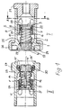
- a coupling part I according to the invention is shown on the right, as it can basically be used alone. It consists of a cylindrical coupling body 8, on the inner wall of which an inner threaded piece 7 is fastened, which has openings as channels 9 to the inner wall. A connection 21 for a hose line is shown at the end.
- a plate 3 which has an annular groove 22, is screwed into the internal threaded piece.
- a sleeve 6 is screwed in from the opposite side and is provided with an annular stop 23 which rests on the edge of the sleeve 6.
- the cylindrical region 10 of a bellows 2 bears against the inner wall of the sleeve 6 and is held from the inside by a metallic spring 1 against the inner wall of the sleeve.
- the spring 1 is supported against the plate 3 and presses a valve cone 4 against a counter cone 25 of the valve body 8.
- the valve cone 4, bellows 2 and cylindrical extension 24 are made in one piece from PTFE (turned), with the end facing the plate 3 the area 10 a collar 5 is formed, the spring 1 is held sealingly between the sleeve 23 and the plate 3 by screwing the two parts against each other.
- such a coupling part can be used on its own, with a counterpart only having to have a central mandrel or the like in order to open the valve cone against the spring tension when coupling.
- the solution shown here is preferred, in which a part II with the same effect is combined with part I.
- the coupling part I has a union nut 26 which connects the two to one another via the thread 27 of the part II.
- Parts I and II have projections 17 projecting beyond the cone 4, which rest in the coupling openings 24.
- the coupling openings 24 or the extensions 17 and the screw connection 26, 27 are dimensioned such that the cones 4 lift off from the counter cones 25 and release the flow path for the liquid.
- a safe, uniform opening of both cones 4 is ensured by a stop 12, which is assigned a weaker spring 1 'in the coupling part II, which is first pushed back by the spring 1 against it.
- the stop 12 can be adjustably mounted in the plate 3 'in a thread.
- the stop 12 can run directly against the cone 4 ', in the illustration the cone 4' has a plunger 14, against which the stop 12 is in the open position of the coupling parts I and II.
- All liquid-carrying parts (not springs 1 and 1 ') are made of plastic (PTFE), so that a high tightness is guaranteed.
- O-rings 27 also made of PTFE can be used.
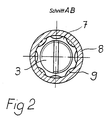
- FIG. 2 shows the section according to FIG. 1.
- the plate 3 is screwed into the internal threaded piece 7.
- the assemblability of the parts can be ensured, for example, by either detachably connecting the internal threaded piece to the coupling body 8 or by making it divisible between the internal threaded piece 7 and the counter cone 25 (FIG. 1).
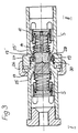
- Fig. 3 shows the two coupling parts I and II in the closed state to form an annular constricted gap around the valve cone 4, 4 'and the extensions 17, 17'.
- the plunger 14 bears against the stop 12, the union nut 26 is screwed to the thread 27.
- the coupling bodies 8 When the clutch is opened, the coupling bodies 8 first move away from one another as a result of the necessary closing travel until the cones 4, 4 'rest on their counter cones 25. This creates a gap between the coupling bodies, which is undesirably filled with liquid, increasing the dead volume.
- the coupling part II has a spring-loaded sealing ring 19 which lies in an annular space 30 and is prestressed by a spring 28.
- a flange 28 of the coupling part I bears against the sealing ring 19 of the coupling part II.
Landscapes
- Engineering & Computer Science (AREA)
- General Engineering & Computer Science (AREA)
- Mechanical Engineering (AREA)
- Quick-Acting Or Multi-Walled Pipe Joints (AREA)
- Rigid Pipes And Flexible Pipes (AREA)
- Lining Or Joining Of Plastics Or The Like (AREA)
Claims (9)
Priority Applications (1)
| Application Number | Priority Date | Filing Date | Title |
|---|---|---|---|
| AT89109300T ATE67570T1 (de) | 1988-06-03 | 1989-05-23 | Kupplung fuer rohre und schlaeuche fuer aggressive fluessigkeiten. |
Applications Claiming Priority (2)
| Application Number | Priority Date | Filing Date | Title |
|---|---|---|---|
| DE3819024 | 1988-06-03 | ||
| DE3819024A DE3819024A1 (de) | 1988-06-03 | 1988-06-03 | Kupplung fuer rohre und schlaeuche fuer aggressive fluessigkeiten |
Publications (2)
| Publication Number | Publication Date |
|---|---|
| EP0344582A1 EP0344582A1 (fr) | 1989-12-06 |
| EP0344582B1 true EP0344582B1 (fr) | 1991-09-18 |
Family
ID=6355843
Family Applications (1)
| Application Number | Title | Priority Date | Filing Date |
|---|---|---|---|
| EP89109300A Expired - Lifetime EP0344582B1 (fr) | 1988-06-03 | 1989-05-23 | Raccord pour tuyaux ou circulent des fluides aggressifs |
Country Status (3)
| Country | Link |
|---|---|
| EP (1) | EP0344582B1 (fr) |
| AT (1) | ATE67570T1 (fr) |
| DE (2) | DE3819024A1 (fr) |
Families Citing this family (13)
| Publication number | Priority date | Publication date | Assignee | Title |
|---|---|---|---|---|
| DE4030381A1 (de) * | 1990-09-26 | 1992-04-02 | Em Technik Gmbh Armaturenbau | Tropffreie kupplung |
| DE4407976C1 (de) | 1994-03-10 | 1995-04-13 | Andreas Szeteli | Hydraulisches Absperrventil |
| DE10014890A1 (de) * | 2000-03-24 | 2001-09-27 | Volkswagen Ag | Kopplungsvorrichtung und Anschlußelement für eine Fluidverbindung |
| GB0111148D0 (en) * | 2001-05-08 | 2001-06-27 | Lanarkshire Technology And Inn | Improved ocean survival unit |
| JP4764045B2 (ja) * | 2005-03-29 | 2011-08-31 | 株式会社東芝 | カプラー |
| JP2006286364A (ja) * | 2005-03-31 | 2006-10-19 | Toshiba Corp | 燃料電池の液注入装置 |
| WO2007117538A2 (fr) * | 2006-04-03 | 2007-10-18 | Innerpulse, Inc. | assemblage d'interconnexion souple pour dispositif medical implantable |
| FR2983786A1 (fr) * | 2011-12-09 | 2013-06-14 | Peugeot Citroen Automobiles Sa | Embout de circuit de liquide de refroidissement d'un conteneur d'energie de vehicule automobile, procede et vehicule automobile associes |
| CN103470893B (zh) * | 2013-09-05 | 2016-10-05 | 张其明 | 高温连接阀 |
| CN106641535B (zh) * | 2015-10-30 | 2018-09-28 | 北京精密机电控制设备研究所 | 一种气体快卸连接器 |
| CN110332391A (zh) * | 2019-08-15 | 2019-10-15 | 河北华整实业有限公司 | 一种矿用子母式管接头 |
| DE102019134586A1 (de) * | 2019-12-16 | 2021-06-17 | Em-Technik Gmbh | Schnellkupplung zum Verbinden |
| JP7664604B2 (ja) * | 2021-03-23 | 2025-04-18 | サーパス工業株式会社 | 圧力検出装置 |
Family Cites Families (3)
| Publication number | Priority date | Publication date | Assignee | Title |
|---|---|---|---|---|
| FR1194058A (fr) * | 1959-11-06 | |||
| US3744751A (en) * | 1971-10-21 | 1973-07-10 | Milwaukee Valve Co Inc | Check valve |
| DE3439876A1 (de) * | 1983-11-02 | 1985-05-15 | Daikin Industries, Ltd., Osaka | Korrosionsbestaendige schnelloesekupplungsvorrichtung |
-
1988
- 1988-06-03 DE DE3819024A patent/DE3819024A1/de not_active Withdrawn
-
1989
- 1989-05-23 EP EP89109300A patent/EP0344582B1/fr not_active Expired - Lifetime
- 1989-05-23 DE DE8989109300T patent/DE58900295D1/de not_active Expired - Fee Related
- 1989-05-23 AT AT89109300T patent/ATE67570T1/de not_active IP Right Cessation
Also Published As
| Publication number | Publication date |
|---|---|
| DE58900295D1 (de) | 1991-10-24 |
| EP0344582A1 (fr) | 1989-12-06 |
| ATE67570T1 (de) | 1991-10-15 |
| DE3819024A1 (de) | 1989-12-14 |
Similar Documents
| Publication | Publication Date | Title |
|---|---|---|
| EP0483751B1 (fr) | Système d'assemblage | |
| DE3708421A1 (de) | Gummielastische dichtung | |
| EP0344582A1 (fr) | Raccord pour tuyaux ou circulent des fluides aggressifs | |
| DE29503585U1 (de) | Anschlußstück für die Rohrleitungskupplung eines Hochdruckreinigungsgeräts | |
| EP0733822A1 (fr) | Unité de piston/cilindre rempli à fluide,un verin à gaz en particulier | |
| DE3737665A1 (de) | Zum verbinden von rohren oder dergleichen vorgesehene vorrichtung | |
| DE3338241A1 (de) | Kupplungselement fuer rohrleitungen, durch die radioaktive stoffe enthaltende medien befoerdert werden | |
| DE1925171A1 (de) | Verbindungsvorrichtung oder Kupplung | |
| CH621646A5 (fr) | ||
| DE2259429A1 (de) | Kupplung zum loesbaren anschluss eines ineinanderliegenden doppelschlauchsystemes an ein geschlossenes containment | |
| DE3610947A1 (de) | Anschluss | |
| EP1048882B1 (fr) | Raccord de tuyaux | |
| DE3306204A1 (de) | Anschlussarmatur fuer einen behaelter | |
| DE3416109A1 (de) | Einrichtung zur schwenk- und loesbaren verbindung zweier winkelig zueinander verlaufenden rohrleitungen | |
| EP0879377A1 (fr) | Raccord amovible pour tuyaux en plastique | |
| DE2412697A1 (de) | Rohrverbindung | |
| DE1536900C3 (de) | Lösbare Befestigungseinrichtung für Filterkörper | |
| DE4318831C2 (de) | Kupplungsvorrichtung für Rohre | |
| EP0286715B1 (fr) | Raccord à vis | |
| EP0596419B1 (fr) | Soupape, en particulier pour un accouplement à boyaux | |
| DE2757003C3 (de) | Ventilkupplung | |
| DE840178C (de) | Schlauch- oder Rohrkupplung | |
| DE842737C (de) | Rohrleitungskupplung | |
| DE1229351B (de) | Rohrverbindung | |
| DE1775923A1 (de) | Verbindungsstueck fuer eine Rohrleitung |
Legal Events
| Date | Code | Title | Description |
|---|---|---|---|
| PUAI | Public reference made under article 153(3) epc to a published international application that has entered the european phase |
Free format text: ORIGINAL CODE: 0009012 |
|
| AK | Designated contracting states |
Kind code of ref document: A1 Designated state(s): AT BE CH DE ES FR GB GR IT LI LU NL SE |
|
| 17P | Request for examination filed |
Effective date: 19891109 |
|
| 17Q | First examination report despatched |
Effective date: 19901112 |
|
| GRAA | (expected) grant |
Free format text: ORIGINAL CODE: 0009210 |
|
| AK | Designated contracting states |
Kind code of ref document: B1 Designated state(s): AT BE CH DE ES FR GB GR IT LI LU NL SE |
|
| ITF | It: translation for a ep patent filed | ||
| PG25 | Lapsed in a contracting state [announced via postgrant information from national office to epo] |
Ref country code: SE Effective date: 19910918 Ref country code: NL Effective date: 19910918 Ref country code: GR Free format text: LAPSE BECAUSE OF FAILURE TO SUBMIT A TRANSLATION OF THE DESCRIPTION OR TO PAY THE FEE WITHIN THE PRESCRIBED TIME-LIMIT Effective date: 19910918 Ref country code: ES Free format text: THE PATENT HAS BEEN ANNULLED BY A DECISION OF A NATIONAL AUTHORITY Effective date: 19910918 Ref country code: BE Effective date: 19910918 |
|
| REF | Corresponds to: |
Ref document number: 67570 Country of ref document: AT Date of ref document: 19911015 Kind code of ref document: T |
|
| REF | Corresponds to: |
Ref document number: 58900295 Country of ref document: DE Date of ref document: 19911024 |
|
| GBT | Gb: translation of ep patent filed (gb section 77(6)(a)/1977) | ||
| ET | Fr: translation filed | ||
| NLV1 | Nl: lapsed or annulled due to failure to fulfill the requirements of art. 29p and 29m of the patents act | ||
| PG25 | Lapsed in a contracting state [announced via postgrant information from national office to epo] |
Ref country code: AT Effective date: 19920523 |
|
| PG25 | Lapsed in a contracting state [announced via postgrant information from national office to epo] |
Ref country code: LU Free format text: LAPSE BECAUSE OF NON-PAYMENT OF DUE FEES Effective date: 19920531 Ref country code: LI Effective date: 19920531 Ref country code: CH Effective date: 19920531 |
|
| PLBE | No opposition filed within time limit |
Free format text: ORIGINAL CODE: 0009261 |
|
| STAA | Information on the status of an ep patent application or granted ep patent |
Free format text: STATUS: NO OPPOSITION FILED WITHIN TIME LIMIT |
|
| 26N | No opposition filed | ||
| REG | Reference to a national code |
Ref country code: CH Ref legal event code: PL |
|
| PGFP | Annual fee paid to national office [announced via postgrant information from national office to epo] |
Ref country code: GB Payment date: 19940504 Year of fee payment: 6 |
|
| PGFP | Annual fee paid to national office [announced via postgrant information from national office to epo] |
Ref country code: FR Payment date: 19940517 Year of fee payment: 6 |
|
| PGFP | Annual fee paid to national office [announced via postgrant information from national office to epo] |
Ref country code: DE Payment date: 19940719 Year of fee payment: 6 |
|
| PG25 | Lapsed in a contracting state [announced via postgrant information from national office to epo] |
Ref country code: GB Effective date: 19950523 |
|
| GBPC | Gb: european patent ceased through non-payment of renewal fee |
Effective date: 19950523 |
|
| PG25 | Lapsed in a contracting state [announced via postgrant information from national office to epo] |
Ref country code: DE Effective date: 19960201 |
|
| PG25 | Lapsed in a contracting state [announced via postgrant information from national office to epo] |
Ref country code: FR Effective date: 19960229 |
|
| REG | Reference to a national code |
Ref country code: FR Ref legal event code: ST |
|
| REG | Reference to a national code |
Ref country code: FR Ref legal event code: ST |
|
| PG25 | Lapsed in a contracting state [announced via postgrant information from national office to epo] |
Ref country code: IT Free format text: LAPSE BECAUSE OF NON-PAYMENT OF DUE FEES Effective date: 20050523 |