EP0344749A2 - Wirbelrohr-Abscheider - Google Patents
Wirbelrohr-Abscheider Download PDFInfo
- Publication number
- EP0344749A2 EP0344749A2 EP89109847A EP89109847A EP0344749A2 EP 0344749 A2 EP0344749 A2 EP 0344749A2 EP 89109847 A EP89109847 A EP 89109847A EP 89109847 A EP89109847 A EP 89109847A EP 0344749 A2 EP0344749 A2 EP 0344749A2
- Authority
- EP
- European Patent Office
- Prior art keywords
- tube
- region
- divergence
- inlet
- downstream
- Prior art date
- Legal status (The legal status is an assumption and is not a legal conclusion. Google has not performed a legal analysis and makes no representation as to the accuracy of the status listed.)
- Granted
Links
Images
Classifications
-
- B—PERFORMING OPERATIONS; TRANSPORTING
- B01—PHYSICAL OR CHEMICAL PROCESSES OR APPARATUS IN GENERAL
- B01D—SEPARATION
- B01D45/00—Separating dispersed particles from gases or vapours by gravity, inertia, or centrifugal forces
- B01D45/12—Separating dispersed particles from gases or vapours by gravity, inertia, or centrifugal forces by centrifugal forces
-
- B—PERFORMING OPERATIONS; TRANSPORTING
- B04—CENTRIFUGAL APPARATUS OR MACHINES FOR CARRYING-OUT PHYSICAL OR CHEMICAL PROCESSES
- B04C—APPARATUS USING FREE VORTEX FLOW, e.g. CYCLONES
- B04C3/00—Apparatus in which the axial direction of the vortex flow following a screw-thread type line remains unchanged ; Devices in which one of the two discharge ducts returns centrally through the vortex chamber, a reverse-flow vortex being prevented by bulkheads in the central discharge duct
-
- B—PERFORMING OPERATIONS; TRANSPORTING
- B04—CENTRIFUGAL APPARATUS OR MACHINES FOR CARRYING-OUT PHYSICAL OR CHEMICAL PROCESSES
- B04C—APPARATUS USING FREE VORTEX FLOW, e.g. CYCLONES
- B04C3/00—Apparatus in which the axial direction of the vortex flow following a screw-thread type line remains unchanged ; Devices in which one of the two discharge ducts returns centrally through the vortex chamber, a reverse-flow vortex being prevented by bulkheads in the central discharge duct
- B04C3/06—Construction of inlets or outlets to the vortex chamber
-
- B—PERFORMING OPERATIONS; TRANSPORTING
- B04—CENTRIFUGAL APPARATUS OR MACHINES FOR CARRYING-OUT PHYSICAL OR CHEMICAL PROCESSES
- B04C—APPARATUS USING FREE VORTEX FLOW, e.g. CYCLONES
- B04C3/00—Apparatus in which the axial direction of the vortex flow following a screw-thread type line remains unchanged ; Devices in which one of the two discharge ducts returns centrally through the vortex chamber, a reverse-flow vortex being prevented by bulkheads in the central discharge duct
- B04C2003/006—Construction of elements by which the vortex flow is generated or degenerated
Definitions
- THIS INVENTION relates to a separating device suitable for use in treating a particle containing gas flow stream to separate particles from the gas or to clean the gas of particles.
- the kind of separating device to which the invention relates can more precisely be described as a vortex tube particle recovery device or as a vortex tube gas cleaning device, depending on which aspect of its operation emphasis is placed.
- This invention more particularly has in mind the cleaning of gas, especially the cleaning of air.
- vortex tube gas cleaning device will be used in the specification.
- upstream and downstream will be used in this specification. These terms should be interpreted in relation to the normal direction of flow through the device in use.
- the invention relates to a vortex tube gas cleaning device or particle recovering device suitable for use in treating a particle containing gas flow stream to clean the gas of particles or to recover particles from the gas, the device comprising an outer round tube having an inlet at one end which will be an upstream end in use; an axially arranged vortex or rotating flow generator in the tube downstream of the inlet; a separation region downstream of the vortex generator; a peripheral outlet region toward the periphery of the tube downstream of the separation region; a central outlet region toward the centre of the tube downstream of the separation region; an inner round extraction tube, arranged concentrically within the outer round tube to separate the peripheral and central outlet regions, having an inlet at an upstream end thereof which is at a predetermined axial position corresponding to the end of the separation region, and an outlet means for the central outlet region at a downstream end thereof; and outlet means for the peripheral outlet region toward a downstream end thereof.
- a particle containing gas flow stream from particles in a gas cleaning device, or recovering particles from a particle containing gas flow stream in a particle recovering device, of the kind described, by introducing the particle containing gas flow stream axially into the outer round tube via its inlet; inducing rotating flow in said particle containing gas flow stream by guiding it through the vortex generator; allowing the particles to concentrate toward the outer periphery of the flow stream on account of the rotating flow; guiding a particle enriched portion of the flow stream, toward the outer periphery of the tube, into the peripheral outlet region; and guiding a particle depleted portion of the flow stream, toward the centre of the tube, into the central outlet region, there is provided the step of allowing the flow, upstream of the peripheral outlet region and the central outlet region, to diverge by providing a divergent portion in the periphery of the outer tube.
- Said divergence may be allowed to take place in the separation region.
- Said divergence may take place over an axial length of the same order of magnitude as the nominal diameter of the tube at the inlet. Thus, it may take place over an axial length between about 0,5 times and about 2 times, preferably between about 0,7 times and 1,5 times, the nominal diameter of the tube.
- the degree of divergence may be such that it increases the flow area by an amount of between about 5% and about 200%, preferably between about 15% and about 60%.
- the included angle of divergence may be between about 2,5° and about 20°, preferably about 5° to 10°.
- the inner periphery may form an angle of about 2,5° to 5° with the axis of the tube.
- such divergence may be allowed to take place in substantially the whole of the region of the vortex generator as well as in the separating region. Then, divergence may take place over an axial length between about time and about 3 times the nominal diameter of the outer tube at its inlet.
- the increase in flow area may be between about 30% and about 800%, preferably between about 500% and and about 600%.
- the included angle of divergence may be between about 7° and about 120°, preferably between about 15° and about 60°, most preferably about 30°.
- the invention extends to a vortex tube gas cleaning device or vortex tube particle recovery device of the kind described and suitable for use in carrying out the method of the invention, in which at least a portion of the periphery of the outer tube upstream of the peripheral outlet region and central outlet region is divergent.
- the divergent portion may be in the separation region.
- the periphery of the outer tube in the region of the vortex generator and the separation region may be divergent.
- the periphery of the vortex generator is preferably correspondingly divergent.
- a central chine of the vortex generator may be divergent, which divergence may be of the same order as the divergence of the vortex generator.
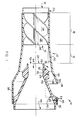
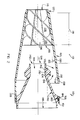
- FIG. 1 and 2 show, in axial sections, two different embodiments of gas cleaning devices in accordance with the invention.
- a first embodiment of a vortex tube gas cleaning device is generally indicated by reference numeral 10.
- the device 10 is generally of symmetrical round shape and is assembled of different components of moulded synthetic plastics material.
- the devices may be of other materials, such as of abrasion-resistant metal, e.g. steel; corrosion-resistent or non-corrosive metal, e.g. steel; or the like.
- the device 10 comprises an outer round tube generally indicated at 12, a vortex generator 16 fitting snugly within the tube 12 toward one end and an inner extraction tube 40 in the form of an inner round tube fitted co-axially within the outer tube 12 toward the opposed end thereof.
- the end having the vortex generator will in use be the upstream end, and the opposed end will be the downstream end.
- the tube 12 has an inlet 14. From the inlet 14, the tube 12 extends parallel for a portion of its length to define a vortex generating region 18 within which the vortex generator 16 is located. At its upstream end, the tube 12 has a mounting formation in the form of a recess 20.
- the vortex generator 16 has a central core or chine 26 and a pair of helical blades 28 arranged around the core 26, auger fashion. Each blade curves through an angle of 180°. At their peripheries, each blade is at an angle of 57° with the axis.
- the wall of the tube 12 diverges as indicated at 30 for a predetermined distance.
- the included angle of divergence is equal to twice the angle 32 between the diverging wall and the axis of the device 10.
- the angle 32 is 5° and the included angle is thus 10°.
- the tube Downstream of the divergent portion 30, the tube diverges more sharply to form a diffuser wall, which will be described in more detail hereinafter, generally indicated by reference numeral 34.
- the tube 12 Downstream of the diffuser wall 34, the tube 12 is parallel as indicated at 38.
- a single outlet port 36 which extends around a portion of the circumference through an angle of about 120°, is provided in the tube 12 in the parallel portion 38.
- the extraction tube 40 has at an upstream end an inlet identified by its leading edge 42 and which leads into a central passage 44 which blends into a diffuser and extends to an outlet 48 of the extraction tube 40.
- the leading edge 42 is at a predetermined axial position of the device 10.
- a separation region 19 is formed between the downstream end of the vortex generator and the leading edge 42. It is to be appreciated that the separation region 19 is divergent as described above.
- an outer peripheral or scavenge region 22 is formed annularly between the inner extraction tube 40 and the outer tube 12; and a central or main outlet region 24 is formed bounded by the inner extraction tube 40. Both the scavenge region 22 and the main outlet region 24 are downstream of the separation region 19.
- An annular inlet to the scavenge region 22 is formed around the leading edge 42. Closely spaced downstream of said inlet, a ring 50 which is integral with the inner extraction tube 40 projects into the scavenge region 22.
- the ring 50 forms an oblique leading wall 52 which, in use, contracts the flow in the scavenge region toward an annular orifice 54 defined annularly outside the crown of the ring 50.
- the diverging wall portion 34 acts like a diffuser in respect of flow downstream of the annular orifice 54.
- the inner extraction tube 40 forms a spigot portion 60, which may be slightly taper if desired.
- the spigot 60 terminates in an outwardly extending flange having a shoulder 62.
- the spigot 60 fits snugly within the end portion 64 of the tube 12 and the end 66 of the tube 12 checks the shoulder 62.
- the inner extraction tube 40 is concentrically and axially located relative to the outer tube 12.
- the inner extraction tube 40 extends cantilever fashion in an upstream direction to render the scavenge region 22 unrestricted.
- the flow passage through the scavenge region 22 including the annular orifice 54 is continuous.
- a particle containing gas flow stream is introduced into the tube 12 via the inlet 14.
- Rotating flow is induced in the flow stream by the vortex generator 16 while the flow stream moves through the vortex generating region 18.
- the rotating flow stream enters the separation region 19, it diffuses outwardly as allowed by the divergence 32.
- the rotating nature of the flow stream causes centrifugal forces to act on the particles, which are heavier than the gas in the flow stream, and to induce the particles to migrate outwardly and concentrate toward the outer periphery of the flow stream.
- the divergence 32 allows the particles to move radially further outwardly than what would have been possible in a parallel separation region.
- the divergence 32 has a secondary, diffuser effect of decelerating the flow thus gaining static pressure in the flow stream at the expense of kinetic or dynamic pressure.
- the decelerated flow also ameliorates wear on the tube 12 which is of importance especially in the case of abrasive particles.
- the particles are concentrated or enriched in the peripheral portion of the flow stream and the central portion of the flow stream is depleted of particles.
- the particle enriched peripheral portion of the flow stream flows into the scavenge region 22, it is first accelerated as it is contracted along the oblique wall 52 into the orifice 54, and is thereafter decelerated along the diffuser wall 34.
- the particle enriched portion of the flow stream moves into a plenum 56 from where it exits via the outlet port 36.
- the particle depleted portion of the flow stream enters the central or main outlet region via the leading edge 42, is diffused in the diffuser and exits via the outlet 48.
- the mass or volume flow ratio of the particle depleted flow stream to the particle enriched flow stream which is referred to as the "cut” is controlled by controlling the pressure ratios between the inlet pressure at the inlet 14 and the pressure downstream of the outlet port 36 on the one hand, and between the inlet 14 and downstream of the outlet 48 on the other hand.
- the diffuser in the central passage 44 gains static pressure at the expense of kinetic or dynamic pressure which reduces the pressure drop between the inlet 14 and the exit 48 and increases the efficiency of the device 10 from an energy consumption point of view.
- the total pressure drop was 4 inch standard water gauge (about 1 kPa)
- the air mass flow was 4,6 gram per second in the main flow stream
- the separation efficiency was more than 98%.
- FIG. 110 another embodiment of a vortex tube gas cleaning device in accordance with the invention is generally indicated by reference numeral 110. It is generally similar to the device 10 of Figure 1 and is not again described. Like reference numerals refer to like parts.
- the device 110 differs from the device 10 in one important respect.
- the outer round tube 112 diverges from its inlet 114 to a position intermediate the annular orifice 154 and the outlet port 136.
- the included angle of divergence in this embodiment, is constant and is about 301 ⁇ 2.
- the outer periphery of the vortex generator 116 diverges correspondingly.
- the core or chine 126 of the vortex generator 116 also diverges, generally at about the same angle as that of the outer tube 112.
- the total pressure drop was 3,4 inch standard water gauge (about 0,85 kPa)
- the air mass flow was 4,7 gram per second in the main flow stream
- the separation efficiency was more than 98%.
- the total pressure drop was 2,8 inch standard water gauge (about 0,7 kPa)
- the air mass flow was 30 gram per second in the main flow stream
- the separation efficiency was 99,7%.
- a diverging type of gas cleaning device When a diverging type of gas cleaning device is compared to a parallel type device of diameter equal to the larger diameter of the diverging device, it is of significance that the swirl (in the diverging device) is initially much more intense resulting in a faster concentration of particles toward the outer periphery, and thus enhances separation.
- the enhanced concentration toward the outer periphery allows one the option of using an inlet of larger diameter, without sacrificing separation efficiency.
- the larger diameter inlet has a significant beneficial affect on the pressure drop and thus the energy consumption.
- a major advantage of the divergent device is that it has a significant benefit in respect of erosion or abrasion. It has been found that erosion is exponentially proportional to the speed, the exponent being higher than 3.
- a divergent separation device especially of the Figure 2 type, can advantageously be used as a primary separator, or as a first stage of a series separator. They have found that a divergent separating device is less prone to blockage than parallel devices of comparable performance - simply stated, if an object with potential for blocking such as a piece of cloth or paper, is present in the flow stream, and can enter the inlet, it can generally pass through the device, more specifically through the peripheral outlet region.
- a separating device in accordance with the invention can generally operate satisfactorily at a 100% cut, i.e. with substantially no gas flow in the peripheral outlet region.
- a 100% cut is in practice achieved by communicating the outlet means for the peripheral outlet region with a closed chamber.
- the chamber will have means to allow emptying thereof from time to time to remove particles. Although this will normally marginally reduce the separation efficiency, it has large advantages in that treatment of the scavenge flow is greatly simplified. Merely the scavenged particles need be processed - there is no scavenge gas flow to process such as by filtration. This has beneficial cost implications.
Landscapes
- Chemical & Material Sciences (AREA)
- Chemical Kinetics & Catalysis (AREA)
- Cyclones (AREA)
- Separating Particles In Gases By Inertia (AREA)
- Filtering Of Dispersed Particles In Gases (AREA)
- Cleaning In General (AREA)
Applications Claiming Priority (2)
| Application Number | Priority Date | Filing Date | Title |
|---|---|---|---|
| ZA883923 | 1988-06-02 | ||
| ZA883923 | 1988-06-02 |
Publications (3)
| Publication Number | Publication Date |
|---|---|
| EP0344749A2 true EP0344749A2 (de) | 1989-12-06 |
| EP0344749A3 EP0344749A3 (en) | 1990-10-31 |
| EP0344749B1 EP0344749B1 (de) | 1995-02-01 |
Family
ID=25579276
Family Applications (1)
| Application Number | Title | Priority Date | Filing Date |
|---|---|---|---|
| EP89109847A Expired - Lifetime EP0344749B1 (de) | 1988-06-02 | 1989-05-31 | Wirbelrohr-Abscheider |
Country Status (20)
| Country | Link |
|---|---|
| US (1) | US4971603A (de) |
| EP (1) | EP0344749B1 (de) |
| JP (1) | JP2878710B2 (de) |
| KR (1) | KR910000213A (de) |
| AR (1) | AR243781A1 (de) |
| AT (1) | ATE117916T1 (de) |
| AU (1) | AU621894B2 (de) |
| BR (1) | BR8902557A (de) |
| CA (1) | CA1327949C (de) |
| DE (1) | DE68920912T2 (de) |
| ES (1) | ES2068217T3 (de) |
| FI (1) | FI89561C (de) |
| FR (1) | FR2632216B1 (de) |
| GB (1) | GB2220873B (de) |
| IE (1) | IE62666B1 (de) |
| IL (1) | IL90501A (de) |
| IT (1) | IT1229432B (de) |
| MX (1) | MX173428B (de) |
| NO (1) | NO177294C (de) |
| PT (1) | PT90737B (de) |
Cited By (7)
| Publication number | Priority date | Publication date | Assignee | Title |
|---|---|---|---|---|
| EP0471426A1 (de) * | 1990-08-15 | 1992-02-19 | Dr. Küttner GmbH & Co. KG | Feststoff-Abscheider für feststoffbelastete Gasströmungen |
| WO2015024096A1 (en) * | 2013-08-22 | 2015-02-26 | Rng Holdings International Limited | Seperator for a gas stream |
| US9610524B2 (en) | 2012-04-02 | 2017-04-04 | Robert McKenzie | Separator for a gas stream |
| US9744489B2 (en) | 2014-07-11 | 2017-08-29 | Robert McKenzie | Phase separator using pressure differential |
| EP3666362A1 (de) | 2018-12-12 | 2020-06-17 | Filtra Group Oy | Vorrichtung und verfahren zur fluidreinigung |
| EP4371645A1 (de) * | 2022-11-21 | 2024-05-22 | Pall Corporation | Trägheitsabscheider und verfahren zur verwendung |
| EP4371644A1 (de) * | 2022-11-21 | 2024-05-22 | Pall Corporation | Trägheitsabscheider und verfahren zur verwendung |
Families Citing this family (31)
| Publication number | Priority date | Publication date | Assignee | Title |
|---|---|---|---|---|
| ZA931264B (en) * | 1992-02-27 | 1993-09-17 | Atomic Energy South Africa | Filtration. |
| ES2171875T3 (es) * | 1997-06-20 | 2002-09-16 | Candy Spa | Limpiador domestico de vacio con ciclon axial. |
| US6113675A (en) * | 1998-10-16 | 2000-09-05 | Camco International, Inc. | Gas separator having a low rotating mass |
| KR100378881B1 (ko) * | 2000-04-17 | 2003-04-08 | 유명기 | 원심력과 관성을 이용한 입자 분리 포집기 |
| DE10029498A1 (de) * | 2000-06-21 | 2002-01-03 | Mann & Hummel Filter | Ansaugsystem |
| EP1520505B1 (de) * | 2000-07-06 | 2006-02-15 | John Herbert North | Verbesserte Staub-/Teilchensammelvorrichtung für Zyklonabscheider |
| WO2003002227A1 (en) * | 2001-06-29 | 2003-01-09 | Black Clawson Company, Inc. | High viscosity hydrocyclone for air removal |
| US20080017031A1 (en) * | 2004-02-13 | 2008-01-24 | Vo Chau T | Gas Filtration System and Filter Cleaning Method |
| RU2263944C1 (ru) * | 2004-07-02 | 2005-11-10 | Общество с ограниченной ответственностью "Авиагаз-Союз" | Регулятор давления непрямого действия с самообогревом |
| US7879123B2 (en) * | 2007-09-27 | 2011-02-01 | Pall Corporation | Inertial separator |
| CA2648805C (en) * | 2008-01-09 | 2011-08-16 | Sandvik Mining And Construction | Downhole tool for rock drilling |
| US8034143B2 (en) | 2008-03-18 | 2011-10-11 | Uti Limited Partnership | Cyclone |
| KR101128847B1 (ko) * | 2009-12-14 | 2012-03-23 | 한국표준과학연구원 | 입자 포획 장치 |
| US8425641B2 (en) | 2010-06-30 | 2013-04-23 | General Electric Company | Inlet air filtration system |
| RU2487059C1 (ru) * | 2011-12-15 | 2013-07-10 | Открытое Акционерное Общество "Московский Вертолётный Завод Им. М.Л. Миля" | Топливная система летательного аппарата |
| GB2505441B (en) * | 2012-08-30 | 2015-05-13 | Hoover Ltd | Cyclonic separator |
| PL3291908T3 (pl) * | 2015-07-01 | 2019-08-30 | Siemens Mobility GmbH | Urządzenie oddzielające do oddzielania cząstek ze strumienia powietrza |
| WO2017104184A1 (ja) * | 2015-12-17 | 2017-06-22 | 臼井国際産業株式会社 | 気液分離装置 |
| WO2017104183A1 (ja) * | 2015-12-17 | 2017-06-22 | 臼井国際産業株式会社 | 気液分離用旋回流発生装置 |
| US9863633B2 (en) * | 2016-02-16 | 2018-01-09 | Leonard Lawrence Donahue | Oxygen and nitrogen enrichment of atmospheric air using an impeller-based apparatus |
| WO2017192647A1 (en) | 2016-05-03 | 2017-11-09 | Carrier Corporation | Inlet for axial fan |
| USD810786S1 (en) | 2016-06-03 | 2018-02-20 | S&B Filters, Inc. | Particle separator for motor vehicle engine intake |
| DE102017005958B3 (de) | 2017-04-06 | 2018-10-11 | Mann+Hummel Gmbh | Filtereinrichtung |
| JP7094091B2 (ja) * | 2017-10-25 | 2022-07-01 | 臼井国際産業株式会社 | 気液分離装置 |
| WO2020046603A1 (en) * | 2018-08-27 | 2020-03-05 | Sierra Nevada Corporation | Low-gravity water capture device with water stabilization |
| CN111889238A (zh) * | 2019-12-20 | 2020-11-06 | 中国航发长春控制科技有限公司 | 一种旋风分离器 |
| BR112021021962A2 (pt) * | 2020-01-21 | 2022-08-16 | Richard Bibby Darren | Equipamento de filtragem de ar ciclônico |
| JP7834658B2 (ja) * | 2020-12-28 | 2026-03-24 | 臼井国際産業株式会社 | 気液分離装置 |
| WO2022210345A1 (ja) * | 2021-03-30 | 2022-10-06 | Jfeスチール株式会社 | サイクロン集塵装置およびサイクロン集塵装置を用いた集塵方法 |
| US20230117200A1 (en) * | 2021-10-14 | 2023-04-20 | Eaton Intelligent Power Limited | In-line debris separtor for liquid |
| CN114308421B (zh) * | 2021-11-23 | 2022-09-27 | 同济大学 | 一种活性污泥中沙粒回收的机械旋流分离装置 |
Family Cites Families (16)
| Publication number | Priority date | Publication date | Assignee | Title |
|---|---|---|---|---|
| US1735298A (en) * | 1927-02-09 | 1929-11-12 | American Blower Corp | Apparatus for collecting dust particles |
| FR1571650A (de) * | 1967-06-19 | 1969-06-20 | ||
| GB1207028A (en) * | 1967-11-14 | 1970-09-30 | Pall Corp | Tubular vortex separator |
| US3590560A (en) * | 1969-07-28 | 1971-07-06 | David B Pall | Tubular vortex air cleaner |
| US3713280A (en) * | 1971-05-17 | 1973-01-30 | Donaldson Co Inc | Ugal air cleaner with static charge dissipating structure19730130 |
| FR2142568B1 (de) * | 1971-06-21 | 1973-05-25 | Sofiltra | |
| CA1005767A (en) * | 1972-07-21 | 1977-02-22 | Robert H. Moen | Gas-liquid separator |
| US3915679A (en) * | 1973-04-16 | 1975-10-28 | Pall Corp | Vortex air cleaner array |
| US3884660A (en) * | 1973-12-07 | 1975-05-20 | Perry Equipment Corp | Gas-liquid separator |
| GB1473099A (de) * | 1974-08-05 | 1977-05-11 | ||
| US4008059A (en) * | 1975-05-06 | 1977-02-15 | The United States Of America As Represented By The Secretary Of The Army | Centrifugal separator |
| US4162906A (en) * | 1977-05-05 | 1979-07-31 | Donaldson Company, Inc. | Side outlet tube |
| DE2918765A1 (de) * | 1979-05-10 | 1980-11-13 | Kloeckner Humboldt Deutz Ag | Fliehkraftstaubabscheidersystem mit mehreren stufen |
| GB2064359B (en) * | 1979-11-29 | 1983-09-21 | Locker Air Maze Ltd | Air filters |
| US4746340A (en) * | 1986-10-28 | 1988-05-24 | Donaldson Company, Inc. | Air cleaner apparatus |
| FR2632215B1 (fr) * | 1988-06-02 | 1992-07-03 | Cyclofil Pty Ltd | Dispositif de separation a tube a tourbillon |
-
1989
- 1989-05-31 DE DE68920912T patent/DE68920912T2/de not_active Expired - Lifetime
- 1989-05-31 EP EP89109847A patent/EP0344749B1/de not_active Expired - Lifetime
- 1989-05-31 FR FR898907171A patent/FR2632216B1/fr not_active Expired - Lifetime
- 1989-05-31 CA CA000601218A patent/CA1327949C/en not_active Expired - Lifetime
- 1989-05-31 ES ES89109847T patent/ES2068217T3/es not_active Expired - Lifetime
- 1989-05-31 AT AT89109847T patent/ATE117916T1/de not_active IP Right Cessation
- 1989-06-01 IL IL9050189A patent/IL90501A/en unknown
- 1989-06-01 FI FI892667A patent/FI89561C/fi active IP Right Grant
- 1989-06-01 US US07/360,070 patent/US4971603A/en not_active Expired - Lifetime
- 1989-06-01 NO NO892235A patent/NO177294C/no not_active IP Right Cessation
- 1989-06-01 AU AU35951/89A patent/AU621894B2/en not_active Expired
- 1989-06-02 KR KR1019890007708A patent/KR910000213A/ko not_active Ceased
- 1989-06-02 AR AR89314074A patent/AR243781A1/es active
- 1989-06-02 PT PT90737A patent/PT90737B/pt not_active IP Right Cessation
- 1989-06-02 IT IT8920766A patent/IT1229432B/it active
- 1989-06-02 MX MX016305A patent/MX173428B/es unknown
- 1989-06-02 GB GB8912729A patent/GB2220873B/en not_active Expired - Lifetime
- 1989-06-02 JP JP1139381A patent/JP2878710B2/ja not_active Expired - Lifetime
- 1989-06-02 BR BR898902557A patent/BR8902557A/pt not_active IP Right Cessation
- 1989-06-12 IE IE178889A patent/IE62666B1/en not_active IP Right Cessation
Cited By (11)
| Publication number | Priority date | Publication date | Assignee | Title |
|---|---|---|---|---|
| EP0471426A1 (de) * | 1990-08-15 | 1992-02-19 | Dr. Küttner GmbH & Co. KG | Feststoff-Abscheider für feststoffbelastete Gasströmungen |
| US9610524B2 (en) | 2012-04-02 | 2017-04-04 | Robert McKenzie | Separator for a gas stream |
| WO2015024096A1 (en) * | 2013-08-22 | 2015-02-26 | Rng Holdings International Limited | Seperator for a gas stream |
| US9744489B2 (en) | 2014-07-11 | 2017-08-29 | Robert McKenzie | Phase separator using pressure differential |
| EP3666362A1 (de) | 2018-12-12 | 2020-06-17 | Filtra Group Oy | Vorrichtung und verfahren zur fluidreinigung |
| WO2020120839A1 (en) | 2018-12-12 | 2020-06-18 | Filtra Group Oy | Device and method for fluid purification |
| US11786917B2 (en) | 2018-12-12 | 2023-10-17 | Filtrabit Oy | Device and method for fluid purification |
| EP4371645A1 (de) * | 2022-11-21 | 2024-05-22 | Pall Corporation | Trägheitsabscheider und verfahren zur verwendung |
| EP4371644A1 (de) * | 2022-11-21 | 2024-05-22 | Pall Corporation | Trägheitsabscheider und verfahren zur verwendung |
| US12246279B2 (en) | 2022-11-21 | 2025-03-11 | Pall Corporation | Inertial separator and method of use |
| US12247535B2 (en) | 2022-11-21 | 2025-03-11 | Pall Corporation | Inertial separator and method of use |
Also Published As
Similar Documents
| Publication | Publication Date | Title |
|---|---|---|
| EP0344749A2 (de) | Wirbelrohr-Abscheider | |
| EP0344750B1 (de) | Wirbelrohr-Abscheider | |
| US3199269A (en) | Particle-from-gas separators | |
| US4378289A (en) | Method and apparatus for centrifugal separation | |
| US2806551A (en) | Centrifugal dust collector with laminar gas flow | |
| GB1425999A (en) | Centrifugal separators | |
| US4285707A (en) | Dust separator for separating dust from flowing gaseous media | |
| ATE276699T1 (de) | Verbesserter luft-teilchenabscheider | |
| US4600410A (en) | Process and apparatus for separating particulate matter from a gaseous medium | |
| JPH1066897A (ja) | サイクロン、特にサイクロン集塵機及びサイクロン分級機 | |
| US2975896A (en) | Hydrocyclone for fibres suspension | |
| JPH05161861A (ja) | サイクロン型集塵装置 | |
| CA1166196A (en) | Centrifugal separator | |
| GB1401331A (en) | Grader for fine-grained material | |
| US4631871A (en) | Abrasive fluid jet apparatus | |
| US3396511A (en) | Vortex separator for solid or liquid aerosols or the like | |
| KR920019420A (ko) | 제분방법 및 장치 | |
| US3094828A (en) | Centrifugal dust separator | |
| US3294236A (en) | Method for pneumatically elutriating solid particles | |
| EP0134361B1 (de) | Vorrichtung und Verfahren zum Abziehen eines Fluids aus einer Zone | |
| JPH0380955A (ja) | ガス循環型サイクロンセパレータ | |
| CA2177581C (en) | Cyclone separation of gaseous fluid flows | |
| GB1592051A (en) | Cyclone separators | |
| GB1075695A (en) | Separating apparatus | |
| JPS55114364A (en) | Axial flow type cyclon |
Legal Events
| Date | Code | Title | Description |
|---|---|---|---|
| PUAI | Public reference made under article 153(3) epc to a published international application that has entered the european phase |
Free format text: ORIGINAL CODE: 0009012 |
|
| AK | Designated contracting states |
Kind code of ref document: A2 Designated state(s): AT BE CH DE ES LI NL SE |
|
| PUAL | Search report despatched |
Free format text: ORIGINAL CODE: 0009013 |
|
| AK | Designated contracting states |
Kind code of ref document: A3 Designated state(s): AT BE CH DE ES LI NL SE |
|
| 17P | Request for examination filed |
Effective date: 19901114 |
|
| 17Q | First examination report despatched |
Effective date: 19921014 |
|
| GRAA | (expected) grant |
Free format text: ORIGINAL CODE: 0009210 |
|
| AK | Designated contracting states |
Kind code of ref document: B1 Designated state(s): AT BE CH DE ES LI NL SE |
|
| REF | Corresponds to: |
Ref document number: 117916 Country of ref document: AT Date of ref document: 19950215 Kind code of ref document: T |
|
| REF | Corresponds to: |
Ref document number: 68920912 Country of ref document: DE Date of ref document: 19950316 |
|
| REG | Reference to a national code |
Ref country code: ES Ref legal event code: FG2A Ref document number: 2068217 Country of ref document: ES Kind code of ref document: T3 |
|
| PGFP | Annual fee paid to national office [announced via postgrant information from national office to epo] |
Ref country code: CH Payment date: 19950515 Year of fee payment: 7 |
|
| PGFP | Annual fee paid to national office [announced via postgrant information from national office to epo] |
Ref country code: AT Payment date: 19950531 Year of fee payment: 7 Ref country code: NL Payment date: 19950531 Year of fee payment: 7 |
|
| PGFP | Annual fee paid to national office [announced via postgrant information from national office to epo] |
Ref country code: BE Payment date: 19950614 Year of fee payment: 7 |
|
| PLBE | No opposition filed within time limit |
Free format text: ORIGINAL CODE: 0009261 |
|
| STAA | Information on the status of an ep patent application or granted ep patent |
Free format text: STATUS: NO OPPOSITION FILED WITHIN TIME LIMIT |
|
| 26N | No opposition filed | ||
| PG25 | Lapsed in a contracting state [announced via postgrant information from national office to epo] |
Ref country code: BE Effective date: 19960531 Ref country code: LI Effective date: 19960531 Ref country code: AT Effective date: 19960531 Ref country code: CH Effective date: 19960531 |
|
| BERE | Be: lapsed |
Owner name: CYCLOFIL (PROPRIETARY) LTD Effective date: 19960531 |
|
| PG25 | Lapsed in a contracting state [announced via postgrant information from national office to epo] |
Ref country code: NL Effective date: 19961201 |
|
| REG | Reference to a national code |
Ref country code: CH Ref legal event code: PL |
|
| NLV4 | Nl: lapsed or anulled due to non-payment of the annual fee |
Effective date: 19961201 |
|
| PGFP | Annual fee paid to national office [announced via postgrant information from national office to epo] |
Ref country code: ES Payment date: 20080619 Year of fee payment: 20 Ref country code: DE Payment date: 20080521 Year of fee payment: 20 |
|
| PGFP | Annual fee paid to national office [announced via postgrant information from national office to epo] |
Ref country code: SE Payment date: 20080512 Year of fee payment: 20 |
|
| REG | Reference to a national code |
Ref country code: ES Ref legal event code: FD2A Effective date: 20090601 |
|
| EUG | Se: european patent has lapsed | ||
| PG25 | Lapsed in a contracting state [announced via postgrant information from national office to epo] |
Ref country code: ES Free format text: LAPSE BECAUSE OF EXPIRATION OF PROTECTION Effective date: 20090601 |