EP0344792A2 - Dispositif de pipettage - Google Patents
Dispositif de pipettage Download PDFInfo
- Publication number
- EP0344792A2 EP0344792A2 EP89109965A EP89109965A EP0344792A2 EP 0344792 A2 EP0344792 A2 EP 0344792A2 EP 89109965 A EP89109965 A EP 89109965A EP 89109965 A EP89109965 A EP 89109965A EP 0344792 A2 EP0344792 A2 EP 0344792A2
- Authority
- EP
- European Patent Office
- Prior art keywords
- piston
- push button
- pipette
- pipetting device
- handle
- Prior art date
- Legal status (The legal status is an assumption and is not a legal conclusion. Google has not performed a legal analysis and makes no representation as to the accuracy of the status listed.)
- Granted
Links
- 238000007789 sealing Methods 0.000 claims abstract description 27
- 239000007788 liquid Substances 0.000 claims abstract description 22
- 230000007423 decrease Effects 0.000 claims abstract description 4
- 230000006835 compression Effects 0.000 claims description 7
- 238000007906 compression Methods 0.000 claims description 7
- 230000007704 transition Effects 0.000 description 3
- 230000000694 effects Effects 0.000 description 2
- 230000000149 penetrating effect Effects 0.000 description 2
- 240000003517 Elaeocarpus dentatus Species 0.000 description 1
- 230000000881 depressing effect Effects 0.000 description 1
- 230000000994 depressogenic effect Effects 0.000 description 1
- 238000011161 development Methods 0.000 description 1
- 230000018109 developmental process Effects 0.000 description 1
- 238000006073 displacement reaction Methods 0.000 description 1
- 230000002209 hydrophobic effect Effects 0.000 description 1
- 238000000034 method Methods 0.000 description 1
- 238000009423 ventilation Methods 0.000 description 1
Images
Classifications
-
- B—PERFORMING OPERATIONS; TRANSPORTING
- B01—PHYSICAL OR CHEMICAL PROCESSES OR APPARATUS IN GENERAL
- B01L—CHEMICAL OR PHYSICAL LABORATORY APPARATUS FOR GENERAL USE
- B01L3/00—Containers or dishes for laboratory use, e.g. laboratory glassware; Droppers
- B01L3/02—Burettes; Pipettes
- B01L3/021—Pipettes, i.e. with only one conduit for withdrawing and redistributing liquids
- B01L3/0217—Pipettes, i.e. with only one conduit for withdrawing and redistributing liquids of the plunger pump type
Definitions
- the invention relates to a pipetting device according to the preamble of claim 1.
- Such a pipetting device is known from DE-PS 914 790 and from DE-PS 698 619. It is used to draw liquid into a pipette and then to push it out of the pipette.
- the object of the invention is to improve the pipetting device specified at the outset.
- this object is achieved by the characterizing features of claim 1.
- the housing-fixed sealing ring In the idle state, the housing-fixed sealing ring is in contact with the first area of the piston; the sealing ring therefore seals.
- the piston is moved by pressing the push button in the guide in the handle. This engages the second area of the piston. Because this second area of the piston in the Diameter is smaller than the diameter of the sealing ring, air can flow through the annular gap between the seal and the second region of the piston into the outflow space and thus into the pipette holder connected to the outflow space. As a result, the pressure equalization caused by this allows the liquid sucked into the pipette to be expressed. It is therefore possible to squeeze out the liquid in the pipette by simply pressing a button.
- the outflow speed can be controlled in a simple manner.
- the annular gap between the sealing ring fixed to the housing and the second region of the piston increases, so that the air flow rate increases in the same way.
- the rate at which the liquid flows out of the pipette can thus be influenced by the extent to which the push button is actuated.
- the second region of the piston is conical, it can be produced in a particularly simple manner. Furthermore, the increase in the annular gap area between the sealing ring fixed to the housing and the second region of the piston is linear with respect to the path of the piston, which results in particularly simple handling.
- a third area adjoining the second area is preferably provided on the piston, in which the diameter initially increases in the direction of the push button until it is the same size as the diameter of the sealing ring and then remains the same.
- the piston can therefore first of all lower be pressed until the beginning of the third area lies against the housing-fixed sealing ring. At this point, the further movement of the piston in the direction of the handle is opposed by a tactile resistance that can be felt as a “pressure point”. In this position, the connection to the outflow chamber is closed again, so that the amount of liquid in the pipette is not changed further, so the process of squeezing liquid out of the pipette is interrupted.
- the piston diameter remains the same, that is, the same size as the diameter of the sealing ring fixed to the housing. If the push button is pressed down further, the outflow chamber remains sealed. If the plunger is depressed further, the volume of the plunger penetrating into the outflow chamber is reduced, as a result of which the residual liquid in the pipette is blown out by this pressure effect.
- the piston therefore works in this third area as a pressure piston.
- the piston is preferably spring-loaded.
- a compression spring can be arranged between a stop on the piston and a stop on the housing.
- the piston can be mounted in a bore in the push button.
- the push button is preferably mounted in a bore in the handle.
- the push button at its end facing the handle has a collar which can be brought into contact with the end face of the bore in the handle, so that the movement of the push button and thus of the piston in the direction away from the handle is limited.
- the push button is in its rest position in contact with the handle. After depressing the push button and then releasing it, the push button returns to this position.
- the piston preferably has a continuous vent hole penetrating the piston transversely. This vent hole preferably extends into the third area. If the piston is moved beyond the second area, no pressure can build up through this vent hole, in which the atmospheric pressure prevails. The piston therefore only acts as a pressure piston when the vent hole has completely passed through the sealing ring, that is to say when the seal is in contact with the third area of the piston which has the same diameter.
- a second piston is mounted for longitudinal displacement, which is provided with a second push button and through which a suction chamber provided in the housing can be controlled, that the suction chamber is connected to the pipette holder via a suction valve and that the suction chamber is connected to a pressure valve.
- the suction chamber is opened by actuating the second push button and thus the second piston.
- the suction valve is opened and the pressure valve is closed.
- the suction space connected to the pipette holder is thus enlarged so that liquid is sucked into the pipette.
- the second piston is preferably spring-loaded.
- the spring can be a second compression spring which is arranged between a stop on the second piston and a stop on the housing.
- the second piston is preferably mounted in a bore of the second push button.
- the second push button can be mounted in a hole in the handle.
- the second push button preferably has a collar on its end facing the handle, which can be brought into contact with the end face of the bore in the handle.
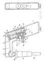
- the pipetting device shown in FIG. 1 has a handle (pistol grip) 1, in which a pipette holder 17 is attached, which enables different types of pipettes 19 to be held.
- a hydrophobic sterile filter 18 is interposed to prevent the ingress of liquid via the pipette holder 17 in the pistol grip 1.
- a cone 11 is arranged in the handle 1, through which the connection to the pipette holder 17 is established.
- a push button 8a is mounted so as to be longitudinally displaceable, the outer end of which pushes out of the handle.
- the push button 8a carries a collar which, in the rest position shown in FIG. 1, lies against the inner end of the guide bore in the handle.
- the push button 8a in turn has an inner bore in which the piston 6 is mounted.
- the piston 6 passes through a sealing ring 13a fixed to the housing.
- the housing block 2 connected to the handle 1 there is one with the piston 6 coaxial bore.
- This consists of an area 41 facing the push button, with a larger diameter 41 and a smaller area 42; the latter forms the outflow space 43.
- the disk 3 lies against a shoulder; this disc 3 is fixed in the bore 41.
- the disk 3 carries the housing-fixed sealing ring 13a on the inside.
- This sealing ring 13a is delimited on one side by a shoulder of the disk 3, while there is a locking ring 20 on the other side. A groove is thus formed between the shoulder of the disk 3 and the locking ring 20, in which the sealing ring 13a lies.
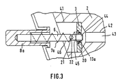
- the piston 6 At its end facing away from the push button 8a, the piston 6 has a first region 44 which corresponds to the diameter of the sealing ring 13a. If this first area 44 of the piston 6 is located in the area of the sealing ring 13a, the outflow space 43 is sealed. A second region 45 adjoins the first region 44 of the piston 6, in which the diameter decreases in the direction of the push button 8a. This second area 45 is conical.
- the second region 45 of the piston 6 reaches the region of the seal 13a fixed to the housing.
- An annular gap is then opened between the seal 13a fixed to the housing and the second region 45 of the piston 6. This annular gap is larger the further the piston 6 is moved to the right. Accordingly, a connection between the area of the bore 41 and the outflow space 43 is opened.
- a third area 46 adjoins the second area 45 of the piston 6, in which the diameter initially increases in the direction of the push button 8a until it is the same size as the diameter of the sealing ring 13a. So if the third region 46 of the piston 6 with the housing-fixed seal 13a in Intervention occurs, the outflow chamber 43 is sealed again.
- a continuous ventilation bore 21 is provided which penetrates the piston 6 transversely. This extends into the third area 46 of the piston 6.
- the outflow space 43 is connected by the hose line 16 to a connection of the cone 11.
- the pushbutton 8a there is a bore which is larger in diameter and adjoins the bore which receives the piston 6.
- a compression spring 7a bears on the shoulder between the two bores mentioned, the other end of which is supported on the disk 3 fixed to the housing.
- the push button 8a and thus the piston 6 is thus spring-loaded.
- pushbutton 8a and piston 6 assume the position shown in FIG. 3.
- the sealing ring 13a fixed to the housing seals the outflow space 43 in that it bears against the first region 44 of the piston 6.
- the piston 6 can then be moved by pressing the pushbutton 8a against the force of the spring 7a.
- a second push button 8 is also mounted to be longitudinally displaceable.
- the second push button 8 likewise has a collar at its end facing the handle 1, which can be brought into contact with the inner end of the bore in the handle 1.
- the second piston 5 is mounted in the second push button 8.
- the second piston 5 passes through a housing-fixed seal 13.
- the seal 13 is located on the inner surface of a disc, which is on a shoulder in a Bore is fixed in the housing body 2.
- the seal 13 is located in a groove which is formed on the one hand by an inwardly facing shoulder of the disc and on the other hand by a ring connected to the disc.
- the last-mentioned ring simultaneously forms the stop fixed to the housing for the spring 7, the other end of which is supported on the second push button 8.
- the piston 5 On the side facing away from the push button 8 of the disk carrying the seal 13, the piston 5 is connected to the piston disk 4, which carries the seal 12 on its outer circumference.
- the piston disc 4 is guided in the housing bore 51.
- This suction chamber is connected to the second connection of the cone 11 via the hose line 15 and a bore in the housing body 2. Both connections of the cone 11 are in turn connected to the pipette holder 17 and thus to the pipette 19.
- the suction valve 14 is arranged between the hose line 15 and the bore in the housing body 2 leading to the suction chamber. Furthermore, the discharge valve 14a is connected to the suction chamber.
- the pipetting device works as follows: During the suction movement, by pressing the second push button 8 via the cylinder-piston unit 51, 4, 5, a negative pressure is generated in the suction space between the seals 13 and 12, which opens the suction valve 14 and at the same time closes the discharge valve 14a .
- the negative pressure causes the liquid to be sucked into the pipette 19 via the hose connection 15 and the cone 11.
- the pipette can therefore be filled by pressing the second push button 8 several times. Since the negative pressure is already generated when the second push button 8 is pressed in via the cylinder-piston unit 4, it is possible to draw in a defined volume of liquid while the second push button 8 is being pushed in.
- the vent hole 21 cannot build up any excess pressure in the transition area 22 between the second area 45 and the third area 46 and also at the beginning of this third area 46, which could lead to a pressure surge.
- the piston 6 is pressed beyond the end of the second region 45, the diameter initially increases in the region 22 of the piston 6.
- the seal 13a seals again. A pressure surge could occur here if the vent hole 21 were not present.
- the vent hole 21 extends somewhat into the third area 46 of the piston 6. Only after this vent hole 21 has completely passed through the seal 13 a does the above-described pressure effect of the third region 46 begin. Through the vent hole 21 a defined start of the action of the piston as a pressure piston is also defined. A pressure surge is prevented.
- the push button 8a can be connected in one piece to the piston 6. The same applies to the second push button 8 and the second piston 5.
Landscapes
- Health & Medical Sciences (AREA)
- Clinical Laboratory Science (AREA)
- Chemical & Material Sciences (AREA)
- Chemical Kinetics & Catalysis (AREA)
- Devices For Use In Laboratory Experiments (AREA)
- Endoscopes (AREA)
- Catching Or Destruction (AREA)
- Pipe Accessories (AREA)
Priority Applications (1)
| Application Number | Priority Date | Filing Date | Title |
|---|---|---|---|
| AT89109965T ATE83174T1 (de) | 1988-06-01 | 1989-06-01 | Pipettiergeraet. |
Applications Claiming Priority (2)
| Application Number | Priority Date | Filing Date | Title |
|---|---|---|---|
| DE3818704 | 1988-06-01 | ||
| DE3818704A DE3818704A1 (de) | 1988-06-01 | 1988-06-01 | Pipettiergeraet |
Publications (3)
| Publication Number | Publication Date |
|---|---|
| EP0344792A2 true EP0344792A2 (fr) | 1989-12-06 |
| EP0344792A3 EP0344792A3 (fr) | 1991-01-23 |
| EP0344792B1 EP0344792B1 (fr) | 1992-12-09 |
Family
ID=6355655
Family Applications (1)
| Application Number | Title | Priority Date | Filing Date |
|---|---|---|---|
| EP89109965A Expired - Lifetime EP0344792B1 (fr) | 1988-06-01 | 1989-06-01 | Dispositif de pipettage |
Country Status (4)
| Country | Link |
|---|---|
| EP (1) | EP0344792B1 (fr) |
| JP (1) | JPH02110323A (fr) |
| AT (1) | ATE83174T1 (fr) |
| DE (2) | DE3818704A1 (fr) |
Cited By (2)
| Publication number | Priority date | Publication date | Assignee | Title |
|---|---|---|---|---|
| EP0873790A3 (fr) * | 1997-04-24 | 1999-09-08 | Walu Labortechnik GmbH | Pipette |
| WO2004062805A1 (fr) * | 2003-01-14 | 2004-07-29 | Pz Htl Spólka Akcyjna | Procede pour remplir de liquide un dispositif de pipetage et dispositif de pipetage |
Families Citing this family (2)
| Publication number | Priority date | Publication date | Assignee | Title |
|---|---|---|---|---|
| PL200757B1 (pl) | 2003-02-11 | 2009-02-27 | Pz Htl Spo & Lstrok Ka Akcyjna | Urządzenie pipetujące |
| USD510629S1 (en) | 2004-01-16 | 2005-10-11 | Heathrow Scientific Llc | Pipette device with pivotable nozzle assembly |
Family Cites Families (5)
| Publication number | Priority date | Publication date | Assignee | Title |
|---|---|---|---|---|
| DE698619C (de) * | 1937-03-25 | 1940-11-14 | Paul Giese | Ansaug- und Ablassvorrichtung fuer Pipetten |
| DE914790C (de) * | 1951-07-13 | 1954-07-08 | Paul Giese | Pipettierapparat |
| US3834240A (en) * | 1973-02-23 | 1974-09-10 | Drummond Scient Co | Apparatus for drawing liquids into, and expelling liquids from, a pipette or the like |
| US3963061A (en) * | 1975-09-16 | 1976-06-15 | Drummond Scientific Company | Apparatus for drawing liquids into, and expelling liquids from a pipette |
| US4624147A (en) * | 1985-11-12 | 1986-11-25 | Drummond Scientific Company | Pipet gun for drawing liquid into and expelling it from a pipet |
-
1988
- 1988-06-01 DE DE3818704A patent/DE3818704A1/de active Granted
-
1989
- 1989-06-01 JP JP1140225A patent/JPH02110323A/ja active Pending
- 1989-06-01 EP EP89109965A patent/EP0344792B1/fr not_active Expired - Lifetime
- 1989-06-01 DE DE8989109965T patent/DE58902939D1/de not_active Expired - Fee Related
- 1989-06-01 AT AT89109965T patent/ATE83174T1/de not_active IP Right Cessation
Cited By (2)
| Publication number | Priority date | Publication date | Assignee | Title |
|---|---|---|---|---|
| EP0873790A3 (fr) * | 1997-04-24 | 1999-09-08 | Walu Labortechnik GmbH | Pipette |
| WO2004062805A1 (fr) * | 2003-01-14 | 2004-07-29 | Pz Htl Spólka Akcyjna | Procede pour remplir de liquide un dispositif de pipetage et dispositif de pipetage |
Also Published As
| Publication number | Publication date |
|---|---|
| ATE83174T1 (de) | 1992-12-15 |
| DE3818704C2 (fr) | 1990-04-12 |
| JPH02110323A (ja) | 1990-04-23 |
| DE3818704A1 (de) | 1989-12-07 |
| DE58902939D1 (de) | 1993-01-21 |
| EP0344792B1 (fr) | 1992-12-09 |
| EP0344792A3 (fr) | 1991-01-23 |
Similar Documents
| Publication | Publication Date | Title |
|---|---|---|
| DE2848433C2 (de) | Sauggerät | |
| DE4039393A1 (de) | Chirurgische evakuiervorrichtung | |
| DE1500597B2 (de) | Tauchrohrzerstäuber | |
| EP0201701A2 (fr) | Dispositif de pulvérisation manuel | |
| DE2651333C3 (de) | Saugpipette | |
| EP0232517A2 (fr) | Pipette | |
| DE3532932A1 (de) | Nietsetzwerkzeug | |
| DE3741185A1 (de) | Steuereinrichtung fuer luftbetriebene werkzeuge | |
| DE2920882C2 (de) | Ventilanordnung an einem Druckgasbehälter, die dessen Entleerung auf einen Druck unterhalb eines Restdruckes verhindert sowie dessen Füllung zuläßt. | |
| DE2607583A1 (de) | Pipette | |
| EP1118313B1 (fr) | Pistolet pour pressuriser du ciment à os avec une seringue à ciment amovible | |
| EP0344792B1 (fr) | Dispositif de pipettage | |
| DE3886658T2 (de) | Pneumatisch betriebene Vorrichtung und Verfahren zur Verwendung. | |
| DE3330578C2 (fr) | ||
| EP0230968B1 (fr) | Pulvérisateur de liquide actionné par de l'air comprimé | |
| DE3044550C2 (de) | Verfahren und Vorrichtung zur Dichtheitskontrolle von Einwegspritzen | |
| EP4497511B1 (fr) | Dispositif de distribution de fluide | |
| DE2711208C2 (de) | Vorrichtung zum Dosieren und Abfüllen insbesondere hochviskoser Medien | |
| DE3739539A1 (de) | Insbesondere fuer manuellen betrieb geeignete praegevorrichtung zum einpraegen von zeichen od. dgl. in eine gegenstandsoberflaeche | |
| DE3247577A1 (de) | Pneumatische signiereinheit | |
| DE2511566C3 (de) | Pneumatisch betätigbares Dosierventil insbesondere für schnell und intensiv bindende Kontaktkleber | |
| DE3347834C2 (de) | Handstück für einen Operationssauger | |
| DE10049507B4 (de) | Pipette | |
| DE2628825B2 (de) | Vorrichtung zum Eintreiben eines Stopfens in das Zapfloch eines Fasses | |
| WO2005094681A1 (fr) | Dispositif pour prelevement de sang capillaire |
Legal Events
| Date | Code | Title | Description |
|---|---|---|---|
| PUAI | Public reference made under article 153(3) epc to a published international application that has entered the european phase |
Free format text: ORIGINAL CODE: 0009012 |
|
| AK | Designated contracting states |
Kind code of ref document: A2 Designated state(s): AT BE CH DE FR GB IT LI LU NL |
|
| PUAL | Search report despatched |
Free format text: ORIGINAL CODE: 0009013 |
|
| AK | Designated contracting states |
Kind code of ref document: A3 Designated state(s): AT BE CH DE FR GB IT LI LU NL |
|
| 17P | Request for examination filed |
Effective date: 19910430 |
|
| 17Q | First examination report despatched |
Effective date: 19910913 |
|
| GRAA | (expected) grant |
Free format text: ORIGINAL CODE: 0009210 |
|
| AK | Designated contracting states |
Kind code of ref document: B1 Designated state(s): AT BE CH DE FR GB IT LI LU NL |
|
| PG25 | Lapsed in a contracting state [announced via postgrant information from national office to epo] |
Ref country code: IT Free format text: LAPSE BECAUSE OF FAILURE TO SUBMIT A TRANSLATION OF THE DESCRIPTION OR TO PAY THE FEE WITHIN THE PRE;WARNING: LAPSES OF ITALIAN PATENTS WITH EFFECTIVE DATE BEFORE 2007 MAY HAVE OCCURRED AT ANY TIME BEFORE 2007. THE CORRECT EFFECTIVE DATE MAY BE DIFFERENT FROM THE ONE RECORDED.SCRIBED TIME-LIMIT Effective date: 19921209 Ref country code: NL Effective date: 19921209 Ref country code: BE Effective date: 19921209 Ref country code: FR Effective date: 19921209 |
|
| REF | Corresponds to: |
Ref document number: 83174 Country of ref document: AT Date of ref document: 19921215 Kind code of ref document: T |
|
| GBT | Gb: translation of ep patent filed (gb section 77(6)(a)/1977) |
Effective date: 19921209 |
|
| REF | Corresponds to: |
Ref document number: 58902939 Country of ref document: DE Date of ref document: 19930121 |
|
| EN | Fr: translation not filed | ||
| NLV1 | Nl: lapsed or annulled due to failure to fulfill the requirements of art. 29p and 29m of the patents act | ||
| PG25 | Lapsed in a contracting state [announced via postgrant information from national office to epo] |
Ref country code: AT Effective date: 19930601 |
|
| PG25 | Lapsed in a contracting state [announced via postgrant information from national office to epo] |
Ref country code: LU Free format text: LAPSE BECAUSE OF NON-PAYMENT OF DUE FEES Effective date: 19930630 |
|
| PLBE | No opposition filed within time limit |
Free format text: ORIGINAL CODE: 0009261 |
|
| STAA | Information on the status of an ep patent application or granted ep patent |
Free format text: STATUS: NO OPPOSITION FILED WITHIN TIME LIMIT |
|
| 26N | No opposition filed | ||
| PGFP | Annual fee paid to national office [announced via postgrant information from national office to epo] |
Ref country code: GB Payment date: 19950517 Year of fee payment: 7 |
|
| PGFP | Annual fee paid to national office [announced via postgrant information from national office to epo] |
Ref country code: DE Payment date: 19950628 Year of fee payment: 7 |
|
| PGFP | Annual fee paid to national office [announced via postgrant information from national office to epo] |
Ref country code: CH Payment date: 19950808 Year of fee payment: 7 |
|
| PG25 | Lapsed in a contracting state [announced via postgrant information from national office to epo] |
Ref country code: GB Effective date: 19960601 |
|
| PG25 | Lapsed in a contracting state [announced via postgrant information from national office to epo] |
Ref country code: LI Effective date: 19960630 Ref country code: CH Effective date: 19960630 |
|
| GBPC | Gb: european patent ceased through non-payment of renewal fee |
Effective date: 19960601 |
|
| REG | Reference to a national code |
Ref country code: CH Ref legal event code: PL |
|
| PG25 | Lapsed in a contracting state [announced via postgrant information from national office to epo] |
Ref country code: DE Effective date: 19970301 |