EP0344968B1 - Sichtanzeigesystem für Fahrzeuge - Google Patents
Sichtanzeigesystem für Fahrzeuge Download PDFInfo
- Publication number
- EP0344968B1 EP0344968B1 EP89305272A EP89305272A EP0344968B1 EP 0344968 B1 EP0344968 B1 EP 0344968B1 EP 89305272 A EP89305272 A EP 89305272A EP 89305272 A EP89305272 A EP 89305272A EP 0344968 B1 EP0344968 B1 EP 0344968B1
- Authority
- EP
- European Patent Office
- Prior art keywords
- area
- informational
- optical element
- display system
- light
- Prior art date
- Legal status (The legal status is an assumption and is not a legal conclusion. Google has not performed a legal analysis and makes no representation as to the accuracy of the status listed.)
- Expired - Lifetime
Links
Images


Classifications
-
- B—PERFORMING OPERATIONS; TRANSPORTING
- B60—VEHICLES IN GENERAL
- B60K—ARRANGEMENT OR MOUNTING OF PROPULSION UNITS OR OF TRANSMISSIONS IN VEHICLES; ARRANGEMENT OR MOUNTING OF PLURAL DIVERSE PRIME-MOVERS IN VEHICLES; AUXILIARY DRIVES FOR VEHICLES; INSTRUMENTATION OR DASHBOARDS FOR VEHICLES; ARRANGEMENTS IN CONNECTION WITH COOLING, AIR INTAKE, GAS EXHAUST OR FUEL SUPPLY OF PROPULSION UNITS IN VEHICLES
- B60K37/00—Dashboards
- B60K37/20—Dashboard panels
-
- Y—GENERAL TAGGING OF NEW TECHNOLOGICAL DEVELOPMENTS; GENERAL TAGGING OF CROSS-SECTIONAL TECHNOLOGIES SPANNING OVER SEVERAL SECTIONS OF THE IPC; TECHNICAL SUBJECTS COVERED BY FORMER USPC CROSS-REFERENCE ART COLLECTIONS [XRACs] AND DIGESTS
- Y10—TECHNICAL SUBJECTS COVERED BY FORMER USPC
- Y10S—TECHNICAL SUBJECTS COVERED BY FORMER USPC CROSS-REFERENCE ART COLLECTIONS [XRACs] AND DIGESTS
- Y10S359/00—Optical: systems and elements
- Y10S359/90—Methods
Definitions
- the present invention relates to informational displays for use in a vehicular environment and more particularly to controlling the angles from which the informational image can be viewed or is projected.
- An exemplary application is a push button informational display as part of an instrument cluster in a vehicle's control system.
- the invention in its most preferred embodiment is particularly designed to prevent the informational display from being projected onto the windshield of the vehicle.
- GB-A-2156292 describes an informational display system for use in a vehicle having at least one passenger seat having a seating surface upon which an occupant sits while travelling in the vehicle, said display system using light of the visible spectrum to view informational indicia and having limited angles of viewing the informational indicia from in front of the display system, comprising: a light transmitting optical element, located in use in said vehicle in a position viewable by an occupant sitting on said seating surface, having a transparent body having a first index of refraction and having at least three, spaced, operative faces, including -
- the present invention provides an informational display system for use in a vehicle in accordance with the preamble to Claim 1 wherein the secondary surface is a decorated surface and the informational indicia element has the informational indicia associated with it to be displayed in use to a first limited area above the seating surface of said passenger seat and in front of said front, light transmitting surface of said optical element using light of the visible spectrum, and undisplayed at a second, limited area different from said first area but also located at a vertical level above the seating surface of said passenger seat and in front of said front, light transmitting surface of said optical element, said front, light transmitting surface being viewable from both said first and said second areas;
- the present invention provides a method of limiting the viewing area of an informational display in a vehicle to a first area and preventing it from being viewed at or projected to a second area, comprising the following steps:
- the present invention utilizes the inherent reflective and refractive optical properties of the informational display itself to control the effective viewing or image projecting angle of the informational display.
- it achieves this by utilizing two "display" surfaces, one containing the informational indicia or graphics to be displaced and the other, decorated, surface having a non-informational display surface, which can be for example either a black or frosted surface.
- the structure and optical properties of the structure are designed to display the desired informational display by refracted light in the desired area of viewing the information, while "displaying" the non-informational, non-light projecting surface by means of "reflected" light off of that surface in all of the other areas in which viewing of the information or the projection of the information is not desired.
- buttons made in accordance with this embodiment contain a light control prism element which controls the viewing and projection angle of the information associated with the button, which can be illuminated or can use natural or other ambient light.
- the designed viewable or projection angle of the informational display of the button depends upon the critical angle of the particular prism design used in the button, as well as on other factors, including the particular geometry and spatial relationship(s) and material(s) used.
- the informational display is included on an applique located behind the prism element and separated therefrom by an air filled gap.
- the "decorated" surface is defined to be merely black or frosted or otherwise diffuse.
- a person in the vehicle would view the refracted image of the informational applique until the critical viewing angle of the prism element was crossed. Once this occurred, the individual would then "view” the "reflected" image from the "decorated” surface, which in essence is a non-image.
- the informational image can only be viewed in the area permitted by the optical properties of the prism and the relative location of the two surfaces, while the non-image is "projected" on to the windshield, eliminating any nighttime reflections from being generated.
- information for example, from telltales, graphics, etc., once visible to other occupants, can be directed so that only the desired occupant may view the information.
- the display for example, the button, need not be illuminated for the view control of the present invention to work. Additionally, a light controlling film may not be required. Also, daytime color can be maintained.
- the constant of Snell's Law is the index of refraction of the other substance or medium. It is noted that the index of refraction of a vacuum is considered to be unity, and for most purposes the index of refraction of air likewise can be assumed to be unity, since its variance is relatively so small (actually equal to 1.0002918). In contrast, the index of refraction of, for example, most of the common glasses used in optical instruments lies between 1.46 and 1.96.
- indices of refraction for various media, it should be understood that these can vary in dependence on the wavelength of the monochromatic light being used in making the measurements. Such measurements are typically taken with a light corresponding to the yellow light from a sodium flame, having a wavelength of 589 nm. or approximately 0.6 x 10 ⁇ 6 meters.
- Figure 1 schematically shows a number of exemplary light rays 1, 2, 3 & 4 diverging from a point source P in a medium of index of refraction n and striking the surface of a second medium of index N at varying angles i , where n is greater than N.
- the sine of the angle of refraction is greater than unity. This may be interpreted to mean that, beyond the critical angle, the ray does not pass into the upper medium but is totally internally reflected at the boundary surface.
- Total internal reflection can occur only when a ray is incident on the surface of a medium whose index is smaller than that of the medium in which the ray is traveling. Such a situation is present, for example, when light is traveling in glass or a transparent plastic and is incident on a boundary with an air interface.
- This critical angle when the reverse is considered, is sometimes called the angle of extinction. This is the limiting angle, where the sine of the transmitted angle of the transmitted ray would begin to exceed 1 . Thus, if one were in a denser medium looking out, this limiting angle would occur when the outside disappeared or, moving from the reverse direction, appeared.
- this limiting angle for water is 48.59°. This effect may be observed when swimming underwater. Outside of the limiting angle, the water surface appears silvery and quite opaque; while, within it, the outside is visible.
- a typical, exemplary vehicle 5 includes a dashboard 6 with various instrument and other informational displays 6A , including an exemplary series of push buttons 6B .
- Exemplary push buttons 6B gathered together in a button cluster, could be the button switches or informational display for the "Select” button for an extensive computerized informational display, the "Twilight Sentinel” for controlling the head lights, the panel dimming switch and the rear window defogger switch, etc., among many others.
- driver's seat 7 with a seating surface 7A upon which the occupant 8 sits.
- seating surface 7A upon which the occupant 8 sits.
- passenger seats typically there will be other passenger seats as well, usually to the side of the driver, as well one or more behind the driver.
- a windshield 9 is positioned in front of the driver 8 and typically extends above the driver's main lines of sight "MLS" .
- MLS main lines of sight
- One of the prime design criteria of this exemplary, preferred embodiment of the present invention is to prevent any light or informational display from the instrument panel or dashboard 6 to be projected unto the windshield 9 , which could possibly distract or block the driver's view of, for example, the road, particularly in the desired clear vision zone "CVZ" ; while, of course, still allowing the driver to view the informational displays on the instrument panel 6 , when the driver glances down.
- Figure 2 is highly simplified for general purposes of illustration and is not at all intended to be a literal, scale drawing.
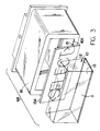
- an exemplary push button 6B in accordance with the present invention includes a transparent optical element 10 having three operative faces - a front, light transmitting face or surface 11 , a refractive face or surface 12 on its backside, and a secondary, "reflective" surface 13 at its bottom between the front and back faces 11 , 12 .
- the refractive surface 12 which also reflects light (depending on the angle of incidence of the light ray), has on its exterior side an air gap 14 (note Fig. 4 ) with an informational indicia element 15 in the form of a graphical applique positioned adjacent or in juxtaposition to it parallel to the angular backside of the optical element 10 .
- the backside face 12 angularly diverges down away from the front face 11 , the angle A between the two being an exemplary 10°.
- the required angle A between the backside 12 and the front side 11 is based on the relationship between the location of the button 6B in the vehicle, compared to the relative angle and position of the windshield 9 (or window).
- the front surface 11 can also serve as the pushing surface for actuating the switch(es) associated with the button.
- the optical element 10 could be made from a number of individual optical sub-elements combined together, if so desired.
- the optical element 10 and its informational or graphical applique 15 are contained within an opaque button housing 16 , which in turn is mounted for switch actuating movement on the instrument panel 6 .
- the illustrated button switch 6B could be, for example, a rectangularly configured rocker switch for a selective display system, such as for example that which is disclosed in U.S. Patent 4,760,218 entitled "Inter-Locked Button Actuated Matrix Switch System, Particularly For Automotive Instrumentation With Button Cluster Switching".
- the applique 15 could have, for example, the informational indicia " ⁇ SELECT >” imprinted thereon, as illustrated, identifying the function of the button and the two, alternate, side directions it can be pushed to, in its "selection” function.
- a button can be back lighted using a secondary light source or can be read by the driver 8 using ambient or natural light.
- the optical element 10 which serves as a lens or prism, could be made of, for example, optical glass or, for greater cost effectiveness, or polycarbonate or acrylic resin, such as, for example, Rohm & Haas' "V920" Plexiglass, which has an index of refraction of .1.491.
- the secondary, reflective surface 13 is a decorated surface, such as for example a black or other darkly colored surface or some diffuse or "wetted" surface, devoid of any informational indicia or display.
- the applique 15 could be applied directly to the backside of the optical element 10 , rather than on a separate, parallel plate or support 15A as illustrated in Figure 4 , there always needs to be some form of an air gap 14 , even a minute one, between them to provide the less dense interfacing medium with a lesser index of refraction (similar to N of Figure 1 ) than that of the optical element 10 (analogous to n of Figure 1 ).
- This air gap 14 can still exist, even when the applique 15 is applied to the backside; however, an intimate contact wetting interface between the two should not be present to insure the existence of some air gap.
- the informational indicia 15 appears to be imprinted on front surface 11 , which serves as the button pushing surface, of the button 16 , it cannot be seen in the effective "reflected" image area 18 , although the viewer or the "CVZ" is still in front of the button.
- the effective fields of view of the areas 17 & 18 may be less than the theoretical ranges when just considering the angles of incidence of the light rays striking internally the back surface 12 , as, for example, occurs due to the lower edge 16A blocking off part of the lower, theoretical, refracted viewing area 17 , and the upper edge 16B blocking off the upper part of the "reflected" viewing area 18 .
- the "reflected image" of the secondary surface 13 is “seen,” which is reflected off of the back surface 12 . Because of the black or darkly colored or diffuse nature of the bottom surface 13 , in essence, “nothing” or “blackness” is “seen.” Thus, the informational display of the indicia on the applique 15 is optically prevented from being projected onto the "CVZ" on the windshield, particularly at night time.
- some baffling or structural block 6C can be included in the dashboard 6 as an auxiliary field restriction technique.
- such limited baffling would be ineffective in eliminating information display or reflection in the indicated " CVZ " as achieved by the present invention in an unobtrusive, aesthetically pleasing manner.
- the surrounding housing 16 also can be used to limit the effective fields of view, and its design also can play a significant role in effecting the desired areas 17 & 18 of informational viewing and non-viewing, respectively.
- the view limiting effect of the housing 16 depends on for example how deeply the backside 12 and the applique 15 are positioned back within the housing 16 and the angle " A " made between them and, for example, the top plane of the housing.
- the present invention can also be used to restrict side viewing, preventing, for example, informational displays from being seen by a non-driver passenger in the vehicle to the side of the driver, or vice-versa.
Landscapes
- Engineering & Computer Science (AREA)
- Chemical & Material Sciences (AREA)
- Combustion & Propulsion (AREA)
- Transportation (AREA)
- Mechanical Engineering (AREA)
- Instrument Panels (AREA)
- Devices For Indicating Variable Information By Combining Individual Elements (AREA)
- Vehicle Waterproofing, Decoration, And Sanitation Devices (AREA)
Claims (20)
- Informationsanzeigesystem zur Verwendung in einem Fahrzeug (5) mit mindestens einem Fahrgastsitz (7) mit einer Sitzfläche (7A), auf der ein Insasse (8) während der Fahrt im Fahrzeug sitzt, wobei das Anzeigesystem Licht des sichtbaren Spektrums zum Darstellen von Informationszeichen benutzt und begrenzte Winkel der Darstellung der Informationszeichen von der Vorderseite des Anzeigesystems her aufweist, umfassend:
ein lichtdurchlässiges optisches Element (10), das im Gebrauch im Fahrzeug in einer für einen auf der Sitzfläche sitzenden Insassen sichtbaren oder betrachtbaren Position angeordnet ist, einen durchsichtigen Körper mit einem ersten Brechungsindex und mindestens drei beanstandete Arbeitsfläche aufweist, einschließlich- einer lichtdurchlässigen Frontfläche (11),- einer inneren Brechfläche (12) und- einer getrennten inneren Sekundärfläche (13), die von der Brechfläche beabstandet ist,ein eine Grenzfläche mit der Brechfläche (12) bildendes Kopplungs- oder Grenzflächenmedium (14) mit einem zweiten, verschiedenen Brechungsindex, der kleiner ist als der erste Brechungsindex, und
ein dem Grenzflächenelement (14) und der Brechfläche (12) des optischen Elements (10) zugeordnetes Informationszeichenelement (15),
dadurch gekennzeichnet,
daß die Sekundärfläche eine dekorierte bzw. verzierte Fläche (13) ist und daß dem Informationszeichenelement (15) die Informationszeichen zugeordnet sind, die im Gebrauch auf einem ersten begrenzten Bereich (17) oberhalb der Sitzfläche (7A) des Fahrgastsitzes (7) und vorderhalb der lichtdurchlässigen Frontfläche (11) des optischen Elements (10) unter Nutzung von Licht des sichtbaren Spektrums darzustellen sind und auf einem zweiten begrenzten Bereich (18) nicht dargestellt werden, der vom ersten Bereich (17) verschieden ist, sich aber ebenfalls an einer lotrechten Ebene oberhalb der Sitzfläche (7A) des Fahrgastsitzes (7) und vorderhalb der lichtdurchlässigen Frontfläche (11) des optischen Elements (10) befindet, wobei die lichtdurchlässige Frontfläche (11) von den beiden der ersten und zweiten Bereiche (17, 18) sichtbar ist, und ferner dadurch gekennzeichnet, daß
die Geometrie des optischen Elements (10) selbst sowie die Relativwinkel und Trennabstände der beabstandeten, lichtdurchlässigen, Brech- und Sekundärflächen (11, 12, 13),- die relativen Brechungsindizes des optischen Elements (10) und des Grenzflächenmediums (14) sowie- die Wellenlänge(n) des in Verbindung mit der Informationsanzeige benutzten Lichts in Kombination angeordnet sind, um vom Zeichenelement kommendes Licht zum ersten Bereich (17) übertragen zu lassen und eine Übertragung des vom Zeichenelement kommenden Lichts zum zweiten Bereich (18) zu verhindern, so daß die Informationszeichen (15) im ersten Bereich (17) sichtbar, im zweiten Bereich (18) aber unsichtbar sind. - Informationsanzeigesystem nach Anspruch 1, bei dem :- die Geometrie des optischen Elements (10) selbst sowie die Relativwinkel und Trennabstände der beabstandeten lichtdurchlässigen, Brech- und Sekundärflächen (11, 12, 13),- die relativen Brechungsindizes des optischen Elements (10) und des Grenzflächenmediums (14) sowie- die Wellenlänge(n) des in Verbindung mit der Informationsanzeige benutzten Lichtsin Kombination auch bewirken, daß zumindest ein Teil des von der getrennten Sekundärfläche (13) kommenden, zum zweiten Bereich (18) zu übertragenden Lichts von der Brechfläche (12) reflektiert wird.
- Informationsanzeigesystem nach Anspruch 1 oder 2, wobei die Sekundärfläche (13) eine reflektierende Innenseite aufweist, die ohne Informationsinhalt ist.
- Informationsanzeigesystem nach einem der Ansprüche 1 bis 3, wobei die Sekundärfläche (13) dunkel gefärbt ist.
- Informationsanzeigesystem nach einem der Ansprüche 1 bis 4, wobei die Sekundärfläche (13) eine diffuse Fläche aufweist.
- Informationsanzeigesystem nach einem der Ansprüche 1 bis 5, wobei der erste Bereich (17) lotrecht unter dem zweiten Bereich (18) angeordnet ist.
- Informationsanzeigesystems nach einem der Ansprüche 1 bis 6, wobei der Fahrzeugaufbau (5) einen Frontscheibenbereich (9) aufweist, der erste Bereich (17) auf einer Augenhöhe für einen auf der Sitzfläche (7A) sitzenden Insassen (8) angeordnet ist und der zweite Bereich (18) der (die) Frontscheibenbereich oder -oberfläche (9) des Fahrzeugaufbaus ist.
- Informationsanzeigesystem nach einem der Ansprüche 1 bis 7, wobei der Fahrzeugaufbau eine Instrumententafel (6) mit mindestens einer Drucktaste (6B) aufweist und das optische Element (10) in die Drucktaste (6B) integriert ist.
- Informationsanzeigesystem nach Anspruch 8, wobei die lichtdurchlässige Frontfläche (11) des optischen Elements (10) die Druck-Frontfläche (11) der Drucktaste (6B) bildet.
- Informationsanzeigesystem nach einem der vorangehenden Ansprüche, wobei die lichtdurchlässige Frontfläche (11) des optischen Elements (10) zumindest im wesentlichen flach und lotrecht angeordnet ist, die Brechfläche (12) zumindest im wesentlichen flach und and der Rückseite des optischen Elements, der Frontfläche im wesentlichen gegenüberstehend, aber abwärts unter einem Winkel (A) von der Frontfläche hinweg divergierend angeordnet ist und die Sekundärfläche (13) an der Unterseite des optischen Elements (10) zwischen der Fontfläche (11) und der Brechfläche (12) angeordnet ist.
- Informationsanzeigesystem nach Anspruch 10, wobei die Rückseite (12) einen Winkel (A) von etwa 10° mit der Frontfläche (11) bildet.
- Informationsanzeigesystem nach einem der vorangehenden Ansprüche, wobei das Grenzflächenmedium (14) aus Luft besteht und das Informationszeichenelement (15) eine auf die Außenseite der Brechfläche aufgetragene Applikation (15) ist.
- Informationsanzeigesystem nach einem der vorangehenden Ansprüche, wobei der Sichtwinkel (17) des ersten Bereichs (17) im wesentlichen innerhalb des kritischen Winkels (ic) der Brechfläche liegt.
- Informationsanzeigesystem nach Anspruch 15, wobei das optische Element (10) innerhalb eines opaken Gehäuses (16) mit einer Vorderkante (16B) enthalten ist, die neben dem Bereich (18) liegt, der von der senkrecht zur inneren Brechfläche (12) verlaufenden Linie (NL) am weitesten entfernt ist.
- Informationsanzeigesystem nach einem der vorangehenden Ansprüche, wobei die Sekundärfläche (13) im wesentlichen flach ist.
- Verfahren zum Begrenzen des Sichtbereichs oder Sehfelds einer Informationsanzeige in einem Fahrzeug auf einen ersten Bereich (17) und zur Verhinderung seiner Sichtbarkeit in einem zweiten Bereich (18), umfassend die folgenden Schritte:(a) Plazieren der darzustellenden Informationszeichen (15) neben einer brechenden Rückseitenfläche (12) eines optischen Prismenelements (10) mit einer lichtdurchlässigen Frontfläche (11), durch welche und aus welcher Licht im sichtbaren Spektrum hindurch- bzw. austreten muß, damit die Zeichen (15) sichtbar sind,und(b) Vorsehen eines Kopplungs- oder Grenzflächenmediums (14) mit einem Brechungsindex, der kleiner ist als der des optischen Elements, zwischen dem Informationszeichen (15) und dem optischen Element (10),
dadurch gekennzeichnet,
daß das Verfahren ferner umfaßt:(c) Vorsehen einer getrennten dekorierten bzw. verzierten Sekundärfläche (13) am optischen Element (10) neben und zwischen der Rückseite (12) und der Frontseite (11) des optischen Elements (10) und(d) Anordnen und Wählen -- der Geometrie des optischen Elements (10) selbst sowie der Relativwinkel und Trennabstände der beabstandeten lichtdurchlässigen, Brech- und Sekundärflächen (11, 12, 13),- der relativen Brechungsindizes des optischen Elements (10) und des Grenzflächenelements (14) sowie- der Wellenlänge(n) des in Verbindung mit der Informationsanzeige benutzten Lichts, um in Kombination das von den Informationszeichen (15) kommende Licht zum ersten Bereich (17) übertragen zu lassen und die Übertragung des von den Zeichenelementen (15) kommenden Lichts zum zweiten Bereich (18) zu verhindern, wobei die Informationszeichen (15) im ersten Bereich (17) sichtbar, im zweiten Bereich (18) aber unsichtbar sind, und um in Kombination zumindest einen Teil des von der getrennten verzierten Sekundärfläche (13) kommenden Lichts zum zweiten Bereich (18) übertragen zu lassen, indem es an der Brechfläche (12) reflektiert wird. - Verfahren nach Anspruch 16, ferner umfassend den folgenden Schritt:
Versehen der Sekundärfläche (13) mit einer reflektierenden Innenseite, die ohne Informationsinhalt ist. - Verfahren nach Anspruch 16 oder 17, ferner umfassend den folgenden Schritt:
Dunkelfärben der reflektierenden Sekundärfläche (13). - Verfahren nach Anspruch 16, 17 oder 18, ferner umfassend den folgenden Schritt:
Versehen der reflektierenden Sekundärfläche (13) mit einer diffusen Oberfläche. - Verfahren nach einem der Ansprüche 16 bis 19, ferner umfassend die folgenden Schritte:
Ausbilden der lichtdurchlässigen Frontfläche (11) des optischen Elements (10) zumindest im wesentlichen flach und in lotrechter Anordnung,
Ausbilden der Brechfläche (12) zumindest im wesentlichen flach und Anordnen derselben an der Rückseite des optischen Elements (10) im wesentlichen in Gegenüberstellung zur Frontfläche (11), aber von der Frontfläche (11) hinweg unter einem Winkel (A) abwärts divergierend, und
Anordnen der Sekundärfläche (13) an der Unterseite des optischen Elements (10) zwischen der Frontfläche (11) und der Brechfläche (12).
Applications Claiming Priority (2)
| Application Number | Priority Date | Filing Date | Title |
|---|---|---|---|
| US07/198,025 US4874224A (en) | 1988-05-24 | 1988-05-24 | Vehicular display view control system |
| US198025 | 1994-02-17 |
Publications (2)
| Publication Number | Publication Date |
|---|---|
| EP0344968A1 EP0344968A1 (de) | 1989-12-06 |
| EP0344968B1 true EP0344968B1 (de) | 1993-03-17 |
Family
ID=22731692
Family Applications (1)
| Application Number | Title | Priority Date | Filing Date |
|---|---|---|---|
| EP89305272A Expired - Lifetime EP0344968B1 (de) | 1988-05-24 | 1989-05-24 | Sichtanzeigesystem für Fahrzeuge |
Country Status (4)
| Country | Link |
|---|---|
| US (1) | US4874224A (de) |
| EP (1) | EP0344968B1 (de) |
| DE (1) | DE68905380T2 (de) |
| ES (1) | ES2039860T3 (de) |
Families Citing this family (18)
| Publication number | Priority date | Publication date | Assignee | Title |
|---|---|---|---|---|
| SE468427B (sv) * | 1990-08-30 | 1993-01-18 | Volvo Ab | Anordning foer att minimera foerstaytesreflexer i en bildskaerm |
| US5448406A (en) * | 1990-08-30 | 1995-09-05 | Ab Volvo | Method and device for minimizing initial surface reflections in a display screen |
| JP2517835Y2 (ja) * | 1991-02-08 | 1996-11-20 | 矢崎総業株式会社 | 車両用表示装置 |
| JP2848499B2 (ja) * | 1991-03-28 | 1999-01-20 | 矢崎総業株式会社 | 車両用表示装置 |
| US5684468A (en) * | 1991-05-29 | 1997-11-04 | Kabushiki Kaisha Tokai Rika Denki Seisakusho | Illuminating display device |
| EP0691798A3 (de) * | 1994-07-05 | 1996-07-17 | Ford Motor Co | Fluoreszente elektrolumineszente Lampe |
| US5504661A (en) * | 1994-07-05 | 1996-04-02 | Ford Motor Company | Translucent fluorescent filter for display panels |
| US5951152A (en) * | 1997-06-17 | 1999-09-14 | Lumex, Inc. | Light source housing apparatus and method of manufacture |
| US6268922B1 (en) * | 1998-12-10 | 2001-07-31 | Litton Systems, Inc. | Method and apparatus for determining fringe number in a fiber-optic gyro |
| US6225579B1 (en) | 1999-08-13 | 2001-05-01 | Thomson Licensing S.A. | Multiple switch assembly including gimbal mounted multifunction for selectively operating multiple switches |
| US6096985A (en) * | 1999-08-13 | 2000-08-01 | Thomson Licensing S.A. | Button assembly |
| US6520667B1 (en) * | 2000-09-15 | 2003-02-18 | Donnelly Corporation | Vehicle interior rearview mirror assembly with display |
| EP1917154A1 (de) * | 2005-08-16 | 2008-05-07 | Johnson Controls Technology Company | Beleuchtetes verkleidungselement für ein armaturenbrett |
| DE102005051965A1 (de) * | 2005-10-29 | 2007-05-03 | GM Global Technology Operations, Inc., Detroit | Kraftfahrzeug und Anzeigevorrichtung |
| US7961455B2 (en) * | 2009-06-05 | 2011-06-14 | Toyota Motor Engineering & Manufacturing North America, Inc. | Display device having guides linking buttons to display information |
| US10099560B2 (en) | 2011-01-26 | 2018-10-16 | Toyota Motor Engineering & Manufacturing North America, Inc. | System and method for maintaining the speed of a vehicle |
| US9008874B2 (en) | 2011-01-26 | 2015-04-14 | Toyota Motor Engineering & Manufacturing North America, Inc. | System and method for managing power in a vehicle |
| DE102015225066A1 (de) * | 2015-12-14 | 2017-06-14 | Continental Automotive Gmbh | Anzeige mit einer beleuchteten Zierleiste |
Family Cites Families (8)
| Publication number | Priority date | Publication date | Assignee | Title |
|---|---|---|---|---|
| US1871877A (en) * | 1929-06-25 | 1932-08-16 | Roland Lord O Brian | Apparatus for correlating spaced points of observation |
| GB1285387A (en) * | 1970-10-14 | 1972-08-16 | Ford Motor Co | Prevention of reflection of light by windscreens in a motor vehicle |
| DE2735251C3 (de) * | 1977-08-04 | 1980-11-06 | Siemens Ag, 1000 Berlin Und 8000 Muenchen | Anordnung zur Darstellung von Betriebsdaten in einem Fahrzeug, insbesondere Kraftfahrzeug |
| DE2942730A1 (de) * | 1979-10-23 | 1981-05-07 | Dr.Ing.H.C. F. Porsche Ag, 7000 Stuttgart | Anzeigesystem fuer zustandsgroessen eines fahrzeuges |
| JPS57182540A (en) * | 1981-05-02 | 1982-11-10 | Matsushita Electric Ind Co Ltd | Head-up display device for vehicle |
| DE3225362C1 (de) * | 1982-07-07 | 1984-01-19 | Opel Adam Ag | Transparente Scheibe zum Abdecken eines unterhalb einer schräg verlaufenden Windschutzscheibe in einer Armaturentafel eines Fahrzeugs angeordneten Instruments |
| JPS60157342U (ja) * | 1984-03-26 | 1985-10-19 | アルプス電気株式会社 | 車載用機器の表示装置 |
| JPS60203545A (ja) * | 1984-03-28 | 1985-10-15 | Nippon Denso Co Ltd | 車両用表示装置 |
-
1988
- 1988-05-24 US US07/198,025 patent/US4874224A/en not_active Expired - Fee Related
-
1989
- 1989-05-24 DE DE8989305272T patent/DE68905380T2/de not_active Expired - Fee Related
- 1989-05-24 EP EP89305272A patent/EP0344968B1/de not_active Expired - Lifetime
- 1989-05-24 ES ES198989305272T patent/ES2039860T3/es not_active Expired - Lifetime
Also Published As
| Publication number | Publication date |
|---|---|
| ES2039860T3 (es) | 1993-10-01 |
| DE68905380T2 (de) | 1993-06-24 |
| DE68905380D1 (de) | 1993-04-22 |
| US4874224A (en) | 1989-10-17 |
| EP0344968A1 (de) | 1989-12-06 |
Similar Documents
| Publication | Publication Date | Title |
|---|---|---|
| US4874224A (en) | Vehicular display view control system | |
| US5198936A (en) | Reflective cluster display | |
| EP0332693B1 (de) | Kraftfahrzeug head-down-anzeigevorrichtung | |
| CN111301166B (zh) | 投影设备 | |
| EP0646823A2 (de) | Virtuell abbildende 3 D Anzeige für Autos | |
| US5334995A (en) | Indication display unit for vehicles | |
| EP0778440B1 (de) | Hintergrundbeleuchtete Farbanzeige | |
| US5519536A (en) | Warning device for displaying information in a vehicle | |
| EP0420196B1 (de) | Sichtanzeigevorrichtung | |
| EP0679549B1 (de) | Headup-Display für ein Fahrzeug | |
| CA1331297C (en) | Holographic display panel for vehicle windshield | |
| CA2001971C (en) | Led array polarized image source/o_ hologram virtual image head up display | |
| EP0498395B1 (de) | Anzeigegerät für Fahrzeug | |
| JPH09330609A (ja) | バックライト装置及びカラー表示装置 | |
| GB2245380A (en) | An automotive display apparatus | |
| JP2000056254A (ja) | 情報表示装置 | |
| Lino et al. | Development of heads-up display for a motor vehicle | |
| JPS62134338A (ja) | 車両用ヘツドアツプデイスプレイ装置 | |
| JPH0596974A (ja) | 車両用表示装置 | |
| JPH0436389B2 (de) | ||
| JPS6353046B2 (de) | ||
| KR100307383B1 (ko) | 차량용표시장치 | |
| KR19990038918A (ko) | 자동차용 헤드업 디스플레이 장치 | |
| JPH0747223Y2 (ja) | 車両用表示装置 | |
| JP3491730B2 (ja) | 車両用計器 |
Legal Events
| Date | Code | Title | Description |
|---|---|---|---|
| PUAI | Public reference made under article 153(3) epc to a published international application that has entered the european phase |
Free format text: ORIGINAL CODE: 0009012 |
|
| AK | Designated contracting states |
Kind code of ref document: A1 Designated state(s): DE ES FR GB IT SE |
|
| 17P | Request for examination filed |
Effective date: 19900601 |
|
| 17Q | First examination report despatched |
Effective date: 19911018 |
|
| GRAA | (expected) grant |
Free format text: ORIGINAL CODE: 0009210 |
|
| AK | Designated contracting states |
Kind code of ref document: B1 Designated state(s): DE ES FR GB IT SE |
|
| ITF | It: translation for a ep patent filed | ||
| PGFP | Annual fee paid to national office [announced via postgrant information from national office to epo] |
Ref country code: FR Payment date: 19930408 Year of fee payment: 5 |
|
| PGFP | Annual fee paid to national office [announced via postgrant information from national office to epo] |
Ref country code: SE Payment date: 19930414 Year of fee payment: 5 |
|
| PGFP | Annual fee paid to national office [announced via postgrant information from national office to epo] |
Ref country code: GB Payment date: 19930415 Year of fee payment: 5 |
|
| PGFP | Annual fee paid to national office [announced via postgrant information from national office to epo] |
Ref country code: DE Payment date: 19930421 Year of fee payment: 5 |
|
| REF | Corresponds to: |
Ref document number: 68905380 Country of ref document: DE Date of ref document: 19930422 |
|
| PGFP | Annual fee paid to national office [announced via postgrant information from national office to epo] |
Ref country code: ES Payment date: 19930428 Year of fee payment: 5 |
|
| ET | Fr: translation filed | ||
| REG | Reference to a national code |
Ref country code: ES Ref legal event code: FG2A Ref document number: 2039860 Country of ref document: ES Kind code of ref document: T3 |
|
| PLBE | No opposition filed within time limit |
Free format text: ORIGINAL CODE: 0009261 |
|
| STAA | Information on the status of an ep patent application or granted ep patent |
Free format text: STATUS: NO OPPOSITION FILED WITHIN TIME LIMIT |
|
| 26N | No opposition filed | ||
| PG25 | Lapsed in a contracting state [announced via postgrant information from national office to epo] |
Ref country code: GB Effective date: 19940524 |
|
| PG25 | Lapsed in a contracting state [announced via postgrant information from national office to epo] |
Ref country code: SE Effective date: 19940525 Ref country code: ES Free format text: LAPSE BECAUSE OF NON-PAYMENT OF DUE FEES Effective date: 19940525 |
|
| GBPC | Gb: european patent ceased through non-payment of renewal fee |
Effective date: 19940524 |
|
| EUG | Se: european patent has lapsed |
Ref document number: 89305272.0 Effective date: 19941210 |
|
| PG25 | Lapsed in a contracting state [announced via postgrant information from national office to epo] |
Ref country code: FR Effective date: 19950131 |
|
| PG25 | Lapsed in a contracting state [announced via postgrant information from national office to epo] |
Ref country code: DE Effective date: 19950201 |
|
| EUG | Se: european patent has lapsed |
Ref document number: 89305272.0 |
|
| REG | Reference to a national code |
Ref country code: FR Ref legal event code: ST |
|
| REG | Reference to a national code |
Ref country code: ES Ref legal event code: FD2A Effective date: 19990503 |
|
| PG25 | Lapsed in a contracting state [announced via postgrant information from national office to epo] |
Ref country code: IT Free format text: LAPSE BECAUSE OF NON-PAYMENT OF DUE FEES;WARNING: LAPSES OF ITALIAN PATENTS WITH EFFECTIVE DATE BEFORE 2007 MAY HAVE OCCURRED AT ANY TIME BEFORE 2007. THE CORRECT EFFECTIVE DATE MAY BE DIFFERENT FROM THE ONE RECORDED. Effective date: 20050524 |