EP0345123B1 - Kraftfahrzeug mit elektrischem Antrieb - Google Patents
Kraftfahrzeug mit elektrischem Antrieb Download PDFInfo
- Publication number
- EP0345123B1 EP0345123B1 EP89401428A EP89401428A EP0345123B1 EP 0345123 B1 EP0345123 B1 EP 0345123B1 EP 89401428 A EP89401428 A EP 89401428A EP 89401428 A EP89401428 A EP 89401428A EP 0345123 B1 EP0345123 B1 EP 0345123B1
- Authority
- EP
- European Patent Office
- Prior art keywords
- motor
- motors
- wheels
- assembly
- vehicle according
- Prior art date
- Legal status (The legal status is an assumption and is not a legal conclusion. Google has not performed a legal analysis and makes no representation as to the accuracy of the status listed.)
- Expired - Lifetime
Links
- 239000000725 suspension Substances 0.000 claims abstract description 20
- 230000009699 differential effect Effects 0.000 claims description 13
- 238000004804 winding Methods 0.000 claims description 9
- 230000001939 inductive effect Effects 0.000 claims 1
- 238000010586 diagram Methods 0.000 description 9
- 239000003990 capacitor Substances 0.000 description 7
- 239000003638 chemical reducing agent Substances 0.000 description 4
- 238000000429 assembly Methods 0.000 description 2
- 238000006073 displacement reaction Methods 0.000 description 2
- 239000006096 absorbing agent Substances 0.000 description 1
- 230000000295 complement effect Effects 0.000 description 1
- 238000010276 construction Methods 0.000 description 1
- 230000000694 effects Effects 0.000 description 1
- 238000000034 method Methods 0.000 description 1
- 230000004048 modification Effects 0.000 description 1
- 238000012986 modification Methods 0.000 description 1
- 238000011084 recovery Methods 0.000 description 1
- 230000001105 regulatory effect Effects 0.000 description 1
- 230000035939 shock Effects 0.000 description 1
- 238000009987 spinning Methods 0.000 description 1
Images

Classifications
-
- B—PERFORMING OPERATIONS; TRANSPORTING
- B60—VEHICLES IN GENERAL
- B60L—PROPULSION OF ELECTRICALLY-PROPELLED VEHICLES; SUPPLYING ELECTRIC POWER FOR AUXILIARY EQUIPMENT OF ELECTRICALLY-PROPELLED VEHICLES; ELECTRODYNAMIC BRAKE SYSTEMS FOR VEHICLES IN GENERAL; MAGNETIC SUSPENSION OR LEVITATION FOR VEHICLES; MONITORING OPERATING VARIABLES OF ELECTRICALLY-PROPELLED VEHICLES; ELECTRIC SAFETY DEVICES FOR ELECTRICALLY-PROPELLED VEHICLES
- B60L50/00—Electric propulsion with power supplied within the vehicle
- B60L50/50—Electric propulsion with power supplied within the vehicle using propulsion power supplied by batteries or fuel cells
- B60L50/52—Electric propulsion with power supplied within the vehicle using propulsion power supplied by batteries or fuel cells characterised by DC-motors
-
- B—PERFORMING OPERATIONS; TRANSPORTING
- B60—VEHICLES IN GENERAL
- B60G—VEHICLE SUSPENSION ARRANGEMENTS
- B60G2200/00—Indexing codes relating to suspension types
- B60G2200/10—Independent suspensions
- B60G2200/14—Independent suspensions with lateral arms
- B60G2200/144—Independent suspensions with lateral arms with two lateral arms forming a parallelogram
-
- B—PERFORMING OPERATIONS; TRANSPORTING
- B60—VEHICLES IN GENERAL
- B60G—VEHICLE SUSPENSION ARRANGEMENTS
- B60G2204/00—Indexing codes related to suspensions per se or to auxiliary parts
- B60G2204/10—Mounting of suspension elements
- B60G2204/30—In-wheel mountings
-
- B—PERFORMING OPERATIONS; TRANSPORTING
- B60—VEHICLES IN GENERAL
- B60G—VEHICLE SUSPENSION ARRANGEMENTS
- B60G2206/00—Indexing codes related to the manufacturing of suspensions: constructional features, the materials used, procedures or tools
- B60G2206/01—Constructional features of suspension elements, e.g. arms, dampers, springs
- B60G2206/10—Constructional features of arms
- B60G2206/124—Constructional features of arms the arm having triangular or Y-shape, e.g. wishbone
-
- B—PERFORMING OPERATIONS; TRANSPORTING
- B60—VEHICLES IN GENERAL
- B60G—VEHICLE SUSPENSION ARRANGEMENTS
- B60G2206/00—Indexing codes related to the manufacturing of suspensions: constructional features, the materials used, procedures or tools
- B60G2206/01—Constructional features of suspension elements, e.g. arms, dampers, springs
- B60G2206/10—Constructional features of arms
- B60G2206/16—Constructional features of arms the arm having a U profile and/or made of a plate
-
- B—PERFORMING OPERATIONS; TRANSPORTING
- B60—VEHICLES IN GENERAL
- B60G—VEHICLE SUSPENSION ARRANGEMENTS
- B60G2300/00—Indexing codes relating to the type of vehicle
- B60G2300/27—Racing vehicles, e.g. F1
-
- B—PERFORMING OPERATIONS; TRANSPORTING
- B60—VEHICLES IN GENERAL
- B60G—VEHICLE SUSPENSION ARRANGEMENTS
- B60G2300/00—Indexing codes relating to the type of vehicle
- B60G2300/50—Electric vehicles; Hybrid vehicles
-
- B—PERFORMING OPERATIONS; TRANSPORTING
- B60—VEHICLES IN GENERAL
- B60L—PROPULSION OF ELECTRICALLY-PROPELLED VEHICLES; SUPPLYING ELECTRIC POWER FOR AUXILIARY EQUIPMENT OF ELECTRICALLY-PROPELLED VEHICLES; ELECTRODYNAMIC BRAKE SYSTEMS FOR VEHICLES IN GENERAL; MAGNETIC SUSPENSION OR LEVITATION FOR VEHICLES; MONITORING OPERATING VARIABLES OF ELECTRICALLY-PROPELLED VEHICLES; ELECTRIC SAFETY DEVICES FOR ELECTRICALLY-PROPELLED VEHICLES
- B60L2200/00—Type of vehicles
- B60L2200/22—Microcars, e.g. golf cars
-
- Y—GENERAL TAGGING OF NEW TECHNOLOGICAL DEVELOPMENTS; GENERAL TAGGING OF CROSS-SECTIONAL TECHNOLOGIES SPANNING OVER SEVERAL SECTIONS OF THE IPC; TECHNICAL SUBJECTS COVERED BY FORMER USPC CROSS-REFERENCE ART COLLECTIONS [XRACs] AND DIGESTS
- Y02—TECHNOLOGIES OR APPLICATIONS FOR MITIGATION OR ADAPTATION AGAINST CLIMATE CHANGE
- Y02T—CLIMATE CHANGE MITIGATION TECHNOLOGIES RELATED TO TRANSPORTATION
- Y02T10/00—Road transport of goods or passengers
- Y02T10/60—Other road transportation technologies with climate change mitigation effect
- Y02T10/70—Energy storage systems for electromobility, e.g. batteries
Definitions
- the invention relates to an electrically powered motor vehicle which can be used in particular as a golf car.
- the object of the present invention is to provide a motor vehicle with electric propulsion, usable as a golf car, said vehicle having a moderate cost price but nevertheless having extremely satisfactory characteristics of movement in uneven terrain.
- a motor vehicle comprising at least two sets of wheels, one front and the other rear, the two sets of wheels being driving and steering, the propulsion of said vehicle being provided by a power source electric on-board, each wheel being equipped with a geared motor group comprising an electric motor powered by the source of electrical energy, the output axis of said group constituting the axis of the corresponding wheel, characterized in that said group is connected to the vehicle chassis by two suspension elements articulated on one side on the unit and on the other on the chassis and that the two motors of the same train are identical and supplied in series, and that a connection comprising a switch is established between the two midpoints located between the two motors in series of the same train to achieve a differential effect.
- connection being established between the two midpoints located between the two motors in series of the same train, in this case, if one of the wheels of the vehicle turns in a vacuum, the wheel which is diagonally opposite is subjected to an increase of its drive torque, which causes the vehicle to pivot which facilitates its release and the resumption of contact with the ground of the wheel which was spinning in a vacuum.
- This connection may possibly be provided only as a result of a special operation by the user.
- each set of wheels has two wheels symmetrical with respect to the median longitudinal plane of the vehicle, the suspension elements being triangles of suspension; advantageously, the articulation of the suspension triangles on the group being a ball joint and that on the chassis being an axis substantially parallel to the longitudinal axis of the vehicle, the group being linked, at a point not carried by the straight line joining the centers from the two ball joints, to a steering member.
- a braking member to be interposed between the wheel and the casing of the geared motor group, one of the elements of said member being integral with said casing and the other being integral with the wheel axle.
- a braking system being interposed between the two aforementioned elements; the ball joints of the suspension triangles on the group can be carried by the gearbox housing of the geared motor group.
- the on-board electric power source is advantageously a battery and the motor of a geared motor group is then a direct current motor; this motor can be a wound rotor motor, the inductor stator comprising permanent magnets.
- the vehicle steering box operated by the user, controls an electronic assembly comprising two identical sub-assemblies assigned one to the two straight wheels and the other to the two wheels.
- one of the two sub-assemblies providing a turn on the inner wheels with an electrical supply which is all the more reduced as the turn is more pronounced, while the other maintains an electrical supply on the outer wheels corresponding to the speed in a straight line.
- the wheels located inside the turn are assigned reduced power in a given proportion, the reduction rate being a function of the radius of curvature of the turn and being programmed to advance.
- the motors can advantageously be supplied via a plurality of transistors connected in parallel, the conduction of said transistors being simultaneous and being controlled at a frequency F during a fraction ⁇ of the control period 1 / F, ⁇ being between 0 and 1 and being an increasing function of the control of the vehicle accelerator.
- the windings of the rotors of the motors associated with each wheel are short-circuited during the fraction (1 - ⁇ ) of the control period when the supply to the motors is cut off.
- motor braking is carried out which is all the more important the shorter the supply time of the motors in each period.
- the presence of such an engine brake is particularly pleasant for driving the vehicle according to the invention.
- the invention also relates to the use of a vehicle, as defined above as a golf cart.
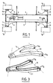
- Each wheel is controlled by direction by the housing 5: this control is designated by 7 for the front wheel 1 a and the direction of the other front wheel 1 b is obtained by a front transverse drawbar 8; the housing 5 operates by a connection 9 a pivoting bracket 10 ⁇ placed at the rear wheels; the bracket 10 ⁇ controls the wheel 1 d of the rear axle by the mechanical link 11 and the orientation is communicated to the wheel 1 c by the rear transverse hitch bar 12. It can therefore be seen that this vehicle has four independent steered wheels.
- a motor-reduction unit is used on each wheel electric 13, which is integral with the wheel and whose output axis constitutes the wheel axis.
- the power supply is provided by a battery on board the vehicle.
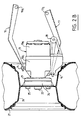
- Each geared motor group 13 consists of a direct current electric motor 13 a and a gear reducer 13 b .
- the outer casing of the reducer 13b carries, at its upper part and at its lower part, a ball joint designated by 14 and 15 respectively.
- the ball joints 14 and 15 constitute the attachment points on the upper 16 and lower 17 suspension triangles; the side of these suspension triangles which is opposite the ball joints 14 and 15 is articulated on the chassis of the vehicle along an axis 18 and 19 respectively.
- Each suspension triangle 16 and 17 consists of two arms which converge towards the point of attachment of the ball joints 14 and 15 respectively, the ends of the two arms which are opposite the ball joint used for articulation on the chassis 2 along the axes 18 and 19 respectively and therefore comprising passages of articulation shafts designated respectively by 16 a and 17 a .
- the springs and shock absorbers of the suspension have not been shown but they are put in place as is well known in the state of the art.
- the line which joins the centers of the ball joints 14, 15 is parallel to the plane defined by the articulation axes 18 and 19 so that during the movement of the suspension triangles 16 and 17 relative to the chassis, the line which joins the centers of the ball joints 14, 15 remains parallel to a fixed plane which makes it possible to maintain the axis of the geared motor group 13 substantially parallel to the ground.
- the wheels 1 a and 1 d are controlled in direction from the steering box 5.
- This control is carried out by providing a lug 20 ⁇ integral with the housing of the reducer 13 b and disposed in a plane substantially parallel to that which is defined by the line of the centers of the ball joints 14, 15 on the one hand and the axis of the geared motor group 13 d ' somewhere else.
- On this lug 20 ⁇ hangs a steering linkage not shown in Figures 2A and 2B.
- the axis of the gear motor 13 can be pivoted about the axis defined by the centers of the two ball joints 14 and 15, which allows the orientation of the wheel.
- the control linkage which comes to cooperate with the lug 20 ⁇ is the transverse attachment bar 8 or 12 respectively.
- a plate 21 On the gear housing 13 b is fixed a plate 21 arranged concentrically around the output shaft 22 of the geared motor; the output shaft 22 is supported in a known manner in the housing of the reducer 13b by bearings 23.
- On the movable flange 24 On the movable flange 24 is fixed, by bolts 25, a wheel rim 26 which supports a tire 27.
- the vehicle which has just been described, comprises four steered wheels with independent suspension, each of these wheels being driving since the wheel axle is the output axle of a geared motor 13.
- the rear axle of the vehicle is not steering.
- the rotational speeds of the axes 22 of the four wheels must be the same; on the other hand, for a movement in a turn, it is necessary to produce a differential effect so that, for a wheel train, the speed of rotation of the inner wheel of the turn is lower than the speed of rotation of the outer wheel.
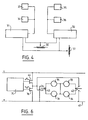
- the first variant is shown diagrammatically in FIGS. 1 and 4.
- the steering box 5 controls, by a potentiometer 30 ⁇ , two identical electronic variators 31 and 32; on the output of the variator 31 are connected in parallel the motors of the front left and rear wheels of the vehicles; on the output of the electronic variator 32 are connected in parallel the front and rear right motors of the vehicle.
- these motors are those which, in the preceding description, have been designated by the single reference 13 a ; but, for the sake of clarity, in the detailed description of this variant as in that of the other two following variants, different references have been assigned to each of these engines; this is how the front left and rear left motors were designated by 33 and 34 respectively and by 35 and 36 the right front and right rear motors respectively.
- the steering box 5 moves in one direction or the other, the cursor of the rheostat 30 which, from a position of equilibrium corresponding to walking in a straight line, favors one or the other of the outputs of the two variators 31 and 32 according to a preset program which corresponds to the desired differential effect.
- the angle of rotation of the steering wheel which corresponds to a given radius of curvature of the turn, the difference to be established between the supply currents of the motors 33 and 34 on the one hand and 35 is programmed. 36 on the other hand.
- the overall speed of the vehicle is controlled by the accelerator, which acts on a rheostat 37 regulating the supply intensity of the motors independently of any reduction affected by one or other of the variators 31 or 32.
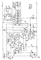
- FIG. 5 The diagram of the electronic circuit allowing the implementation of this variant is represented in FIG. 5; we see that we have kept the references 33 and 35 for the two front left and right engines and 34 and 36 for the two rear left and right engines respectively.
- a connection 40 ⁇ has established a connection between the midpoints between the motors 33 and 35, on the one hand, and 34 and 36, on the other hand.
- the motors 33 to 36 are all identical: they are wound armature motors comprising a stator with permanent magnets; for such motors the torque is proportional to the current.
- the 40 ⁇ switch is closed and one of the vehicle wheels turns in a vacuum due to an accident on the ground, the current which is no longer absorbed by the wheel that turns in a vacuum is taken up by the motor of the diagonally opposite wheel which allows the vehicle to be released in the event of difficult passage.
- the positive 24 V direct current supply line is designated by 41, the negative terminal of the supply battery being connected to ground.
- Power is supplied to the engines of the vehicle for forward or reverse travel by means of switches 42 and 43, which are operated simultaneously.
- the switches 42 and 43 are in the stop position, since the motor windings are short-circuited.
- the motors are fed in forward gear; in the position shown in dotted lines, the motors are powered in reverse.
- Power is supplied between, on the one hand, the line 41 and, on the other hand, a set of transistors 44 arranged in parallel.
- transistors 44 It is necessary to have in parallel a certain number of transistors 44 taking into account the current limitations in these transistors and the consumption of the vehicle engines; if you must consume 10 ⁇ 0 ⁇ amps in total, you need at least seven MOS type transistors in parallel since each can only support about 15 amps. All the transistors 44 are controlled by the voltage supplied on the line 45 so that these transistors are only on for a fraction of the time.
- the transistors 44 will be driven at a certain frequency and, in each period, the transistors will only be on for a fraction of a period; by varying this fraction, an average supply current will be obtained which will be variable from zero to a maximum, which makes it possible to perfectly regulate the speed of movement of the vehicle by acting on the fraction of the period during which the transistors 44 are on.
- the armature windings of the motors 33 to 36 smooth the chopped current due to their self-inductance, so that the output speed of the motors corresponds to the average value of the current itself as a function of the chopping rate in each period.
- Diodes 46 were arranged in parallel at the terminals of the motors 33 to 36; these diodes are SCHOTKY type diodes and they are useful for avoiding a loss of energy each time the current at the output of the transistors 44 is cut off.
- the motors are supplied with a chopped current, each time the power is cut, the induced winding of the motors constitutes a self-discharge which must be recharged when the supply current is re-established.
- a freewheeling diode is provided in known manner and the SCHOTKY diodes are advantageous for this purpose because they have a low threshold and a high conduction speed.
- a line 47 is produced on which there is a stabilized 12 volt voltage; this is obtained by connecting the line 47 to the line 41 by a resistor 48 and by connecting the line 47 to the ground by a capacitor 49 and a Zenner diode 50 ⁇ arranged in parallel.
- a capacitor 54 is provided at the terminals of the resistor 53.
- the resistor 52 is associated with a slider 55 to constitute a rheostat; the cursor 55 is operated by the accelerator of the vehicle; if it is in the low position in FIG.
- the tension in triangular teeth has a period P; during part of this period, the value of the voltage obtained at point 58 of the diagram is greater than that of the voltage obtained at point 56 and, in this case, a voltage is obtained at the output of comparator 57, while during the rest of the period this output is at zero voltage.
- a voltage in rectangular slots is therefore obtained at the output 59 of the comparator 57, the chopping rate of which is a function of the position of the cursor 55 and, consequently, of the vehicle accelerator.
- This voltage in slots 59 is sent to a transistor circuit designated by 60 ⁇ as a whole, said circuit having the role of amplifying the signal it receives from output 59; the circuit 60 ⁇ therefore provides at the output at point 61, that is to say on the gates of the transistors 44 ,, a signal in rectangular slots having the period P and having a value sufficient to control the transistors 44.
- the supply current of the motors 33 to 36 is identified by taking the voltage across a resistor 61 interposed between the transistors 44 and the mass. The average value of this voltage is obtained by a capacitor 62 and it is sent to the negative input of a comparator 63. On the positive input of this comparator 63, a reference voltage obtained by a rheostat 64 is applied. At the output of comparator 63, a voltage is obtained which is made to act on the positive input of comparator 57 to limit the supply current of the vehicle engines as a function of the set value given by the rheostat 64.
- a capacitor 65 is charged and discharged disposed between earth and point 58 of the circuit, this charge and this discharge taking place through a resistor 66 connected between point 58 and the output of a bi-stable 67.
- the bi-stable 67 consists of two NAND doors 68 and 69 looped together, that is to say that the output of one is connected to one of the inputs of the other; one of these input-output connections constitutes the output of the bi-stable 67 and the terminals of the two doors 68 and 69, which are not used for looping, are connected to the line 47 by means of two resistors 70 ⁇ and 71 whose value is equal to that of the resistor 66.
- the point 58 is connected to the negative input of a comparator 72 and to the positive input of a comparator 73; the outputs of the comparators 72 and 73 are connected respectively to the terminals of the gates 68 and 69, which are connected to the line 47.
- the positive terminal of the comparator 72 is connected to the midpoint located between the resistors 51 and 52; the negative input of comparator 73 is connected to the midpoint located between resistors 52 and 53.
- the circuit shown in FIG. 5 allows, as a function of the position of the cursor 55 linked to the accelerator of the vehicle, to obtain a current on the motors 33 to 36, the average value of which varies between zero and the maximum value imposed by the rheostat 64, the differential effect being obtained automatically by the series connection of the two motors of the same train.
- FIG. 6 there is shown schematically a third variant of supply of the motors 33 to 36 of the vehicle according to the invention.
- This variant derives from that of FIG. 5 and provides, in the same way, for the series connection of the two motors of the same train to obtain the differential effect; but it also makes it possible to provide an engine brake function.
- the supply current of the motors becomes zero but no braking is manifested, which obliges , if necessary, to slow the vehicle down by the braking devices 21, 24 associated with each wheel.
- an engine brake can be created electrically.
- transistors 76 of MOS type analogous to transistors 44 and in equivalent number.
- transistors 76 are in phase opposition with respect to transistors 44 that is to say, they are on when the transistors 44 are blocked and vice versa.
- the transistors 76 connect the output of the switch 43 to the line 41: it follows that when they are on, the transistors 76 ensure a short-circuiting of the induced windings of the motors 33 to 36, which ,, well understood, brakes the motor during the time during which the transistors 76 are on.
- the embodiments described above are in no way limiting and may give rise to any desirable modification, without thereby departing from the scope of the invention as defined by the claims.
- the invention may find its application for golf carts or vehicles of all types, for example for the transport of people or luggage in hotels. These vehicles may have more than two sets of wheels, especially if they are all-terrain vehicles.
Landscapes
- Engineering & Computer Science (AREA)
- Sustainable Development (AREA)
- Sustainable Energy (AREA)
- Power Engineering (AREA)
- Transportation (AREA)
- Mechanical Engineering (AREA)
- Life Sciences & Earth Sciences (AREA)
- Electric Propulsion And Braking For Vehicles (AREA)
- Arrangement Or Mounting Of Propulsion Units For Vehicles (AREA)
- Automatic Cycles, And Cycles In General (AREA)
- Lens Barrels (AREA)
- Reciprocating, Oscillating Or Vibrating Motors (AREA)
- Vehicle Interior And Exterior Ornaments, Soundproofing, And Insulation (AREA)
- Vehicle Body Suspensions (AREA)
- Valve Device For Special Equipments (AREA)
- Air-Conditioning For Vehicles (AREA)
Claims (12)
- Kraftfahrzeug mit mindestens zwei Radsätzen (1a, 1b, 1c, 1d), der eine hinten und der andere vorne, wobei es sich bei den beiden Radsätzen um angetriebene und gelenkte Radsätze handelt und der Antrieb des Fahrzeugs von einer elektrischen Stromquelle im Fahrzeug bereitgestellt wird und jedes Rad mit einem Motor-Getriebe-Aggregat (13) ausgestattet ist, das einen von der elektrischen Stromquelle gespeisten Elektromotor umfaßt, und die Abtriebswelle (22) des Aggregats (13) die Achse des entsprechenden Rades bildet, dadurch gekennzeichnet, daß das Aggregat (13) über zwei Aufhängungselemente (16, 17), die auf der einen Seite am Aggregat (13) und auf der anderen Seite am Fahrgestell (2) angelenkt sind, mit dem Fahrgestell (2) des Fahrzeugs verbunden ist und daß die beiden Motoren (33, 35; 34, 36) desselben Satzes gleich sind und in Reihe gespeist werden und daß zur Erzielung einer Differentialwirkung eine einen Schalter (40) umfassende Verbindung zwischen den beiden mittleren Punkten hergestellt wird, die sich zwischen den beiden in Reihe geschalteten Motoren desselben Satzes befinden.
- Kraftfahrzeug nach Anspruch 1, dadurch gekennzeichnet, daß jeder Radsatz zwei zur mittleren Längsebene des Fahrzeugs symmetrische Räder umfaßt und daß es sich bei den Aufhängungselementen um Aufhängungs-Querlenker handelt.
- Kraftfahrzeug nach Anspruch 2, dadurch gekennzeichnet, daß das Aggregat an einem Punkt (20) mit einem Lenkglied verbunden ist, der nicht auf der die Mittelpunkte der beiden Kugelgelenke verbindenden Geraden liegt, wobei es sich bei der Gelenkverbindung des Aufhängungs-Querlenkers (16, 17) mit dem Aggregat (13) um ein Kugelgelenk (14, 15) und bei der mit dem Fahrgestell (2) um eine Achse (18, 19) handelt, die im wesentlichen parallel zur Längsachse des Fahrzeugs verläuft.
- Kraftfahrzeug nach einem der Ansprüche 1 bis 3, dadurch gekennzeichnet, daß zwischen dem Rad und dem Gehäuse des Motor-Getriebe-Aggregats ein Bremsglied angeordnet ist, wobei eines der Elemente (21) des Glieds fest mit dem Gehäuse und das andere (24) fest mit der Achse (22) des Rads verbunden und eine Bremsanlage zwischen den beiden obengenannten Elementen angebracht ist.
- Kraftfahrzeug nach Anspruch 3, dadurch gekennzeichnet, daß die Kugelgelenke (14, 15) zur Gelenkverbindung der Querlenker (16, 17) der Aufhängung mit dem Aggregat (13) von dem Gehäuse des Untersetzungsgetriebes (13b) des Motor-Getriebe-Aggregats (13) getragen werden.
- Kraftfahrzeug nach einem der Ansprüche 1 bis 5, dadurch gekennzeichnet, daß es sich bei der elektrischen Stromquelle im Fahrzeug um eine Batterie und bei dem Motor (13a) eines Motor-Getriebe-Aggregats um einen Gleichstrommotor handelt.
- Kraftfahrzeug nach Anspruch 6, dadurch gekennzeichnet, daß es sich bei dem Motor (13a) eines Motor-Getriebe-Aggregats (13) um einen Motor handelt, der einen induzierten Schleifringläufer und einen induzierenden Ständer mit Dauermagneten aufweist.
- Kraftfahrzeug nach Anspruch 1, dadurch gekennzeichnet, daß das von dem Benutzer bediente Lenkgehäuse (5) des Fahrzeugs ein elektronisches System steuert, das zwei gleiche Untersysteme (31, 32) umfaßt, von denen das eine den beiden rechten Rädern und das andere den beiden linken Rädern des Fahrzeugs zugeordnet ist, wobei das eine der beiden Untersysteme beim Kurvenfahren die Innenräder mit elektrischer Leistung versorgt, die um so geringer ist, je enger die Kurve ist, während das andere eine elektrische Leistungsversorgung der Außenräder aufrechterhält, die dem Fahren auf einer Geraden entspricht.
- Kraftfahrzeug nach Anspruch 1, dadurch gekennzeichnet, daß die Motoren (33 bis 36) über mehrere parallelgeschaltete Transistoren (44) versorgt werden, wobei die Transistoren gleichzeitig eingeschaltet werden, und zwar bei einer Frequenz F während eines Anteils τ der Steuerperiode (1/F), wobei τ zwischen 0 und 1 liegt und in Abhängigkeit der Steuerung des Gaspedals des Fahrzeugs ansteigt.
- Kraftfahrzeug nach den Ansprüchen 7 und 9 zusammengenommen, dadurch gekennzeichnet, daß während des Anteils (1 - τ) der Steuerperiode, wenn die Versorgung der Motoren (33 bis 36) unterbrochen ist, die Wicklungen der Läufer kurzgeschlossen werden.
- Kraftfahrzeug nach Anspruch 10, dadurch gekennzeichnet, daß die Wicklungen der Läufer durch mindestens einen Transistor (76) kurzgeschlossen werden, der gegenüber denen (44), die die Motoren (33 bis 36) versorgen, in Gegenphase leitet.
- Verwendung eines Fahrzeugs nach einem der Ansprüche 1 bis 11 als Golfwagen.
Priority Applications (1)
| Application Number | Priority Date | Filing Date | Title |
|---|---|---|---|
| AT89401428T ATE100027T1 (de) | 1988-05-31 | 1989-05-25 | Kraftfahrzeug mit elektrischem antrieb. |
Applications Claiming Priority (2)
| Application Number | Priority Date | Filing Date | Title |
|---|---|---|---|
| FR8807243A FR2631902B1 (fr) | 1988-05-31 | 1988-05-31 | Vehicule automobile a propulsion electrique |
| FR8807243 | 1988-05-31 |
Publications (2)
| Publication Number | Publication Date |
|---|---|
| EP0345123A1 EP0345123A1 (de) | 1989-12-06 |
| EP0345123B1 true EP0345123B1 (de) | 1994-01-12 |
Family
ID=9366789
Family Applications (1)
| Application Number | Title | Priority Date | Filing Date |
|---|---|---|---|
| EP89401428A Expired - Lifetime EP0345123B1 (de) | 1988-05-31 | 1989-05-25 | Kraftfahrzeug mit elektrischem Antrieb |
Country Status (9)
| Country | Link |
|---|---|
| US (1) | US5004061A (de) |
| EP (1) | EP0345123B1 (de) |
| JP (1) | JPH0277327A (de) |
| AT (1) | ATE100027T1 (de) |
| AU (1) | AU610403B2 (de) |
| CA (1) | CA1329912C (de) |
| DE (1) | DE68912204T2 (de) |
| ES (1) | ES2049832T3 (de) |
| FR (1) | FR2631902B1 (de) |
Cited By (1)
| Publication number | Priority date | Publication date | Assignee | Title |
|---|---|---|---|---|
| EP3946985A1 (de) * | 2019-03-29 | 2022-02-09 | Protean Electric Limited | Doppelquerlenkeraufhängungssystem für einen radinternen elektromotor |
Families Citing this family (31)
| Publication number | Priority date | Publication date | Assignee | Title |
|---|---|---|---|---|
| FR2655005B1 (fr) * | 1989-11-27 | 1994-04-08 | Andruet Jean Claude | Dispositif de commande du frein de parc pour un vehicule automobile. |
| JP2863234B2 (ja) * | 1989-12-27 | 1999-03-03 | アイシン・エィ・ダブリュ株式会社 | 電動車両 |
| JPH0496603A (ja) * | 1990-08-08 | 1992-03-30 | Aisin Aw Co Ltd | 電動車両における衝突防止装置 |
| DE4431305C2 (de) * | 1994-09-02 | 2000-11-23 | Auwaerter Gottlob Gmbh & Co | Omnibus |
| US5590605A (en) * | 1995-11-20 | 1997-01-07 | The Walt Disney Company | Conveying device with self steering powered caster |
| US5788003A (en) * | 1996-01-29 | 1998-08-04 | Spiers; Kent | Electrically powered motor vehicle with linear electric generator |
| US5921338A (en) * | 1997-08-11 | 1999-07-13 | Robin L. Edmondson | Personal transporter having multiple independent wheel drive |
| NL1008060C2 (nl) | 1998-01-19 | 1999-07-20 | Stichting Platform Hoogwaardig | Voertuig, in het bijzonder een elektrisch aangedreven voertuig. |
| JP3664984B2 (ja) * | 2001-02-15 | 2005-06-29 | 独立行政法人科学技術振興機構 | 電気自動車のサスペンション機構 |
| US20040216929A1 (en) * | 2003-04-30 | 2004-11-04 | Catherine White | Solar powered transporter with stabilized speed control and clutch controlled steering |
| US20040222030A1 (en) * | 2003-05-09 | 2004-11-11 | Visteon Global Technologies, Inc. | Vehicle rear suspension support assembly with integrated electric drive |
| JP3840461B2 (ja) * | 2003-05-15 | 2006-11-01 | 清水 浩 | 8輪駆動の電気自動車 |
| US8925659B2 (en) * | 2004-05-07 | 2015-01-06 | Charles E. Wilson | Electric utility vehicle |
| WO2005110791A2 (en) | 2004-05-07 | 2005-11-24 | Wilson Charles E | Electric golf cart and utility cart |
| FR2874548B1 (fr) * | 2004-08-24 | 2006-10-20 | Peugeot Citroen Automobiles Sa | Carter perfectionne pour moteur roue |
| JP2006219082A (ja) * | 2005-02-14 | 2006-08-24 | Hitachi Ltd | 車両用回転電機システム |
| ATE463370T1 (de) * | 2006-01-27 | 2010-04-15 | Fondazione Torino Wireless | Seitlich neigbares fahrzeug |
| JP5292626B2 (ja) * | 2008-11-12 | 2013-09-18 | Ntn株式会社 | インホイールモータ駆動装置およびインホイールモータ駆動装置用ケーシング |
| JP2011240765A (ja) * | 2010-05-17 | 2011-12-01 | Ntn Corp | インホイールモータ駆動装置 |
| CN102009576B (zh) * | 2010-12-01 | 2013-04-17 | 同济大学 | 单纵臂悬架减速式轮边电驱动系统 |
| US9102205B2 (en) * | 2011-02-01 | 2015-08-11 | Polaris Industries Inc. | All terrain vehicle |
| US8950540B2 (en) * | 2011-10-12 | 2015-02-10 | Wfk & Associates, Llc | Environment adaptive electric vehicle with lock on security and control saddle |
| ITTO20110926A1 (it) * | 2011-10-17 | 2013-04-18 | Giorgio Randazzo | Kit di sospensione a ruote indipendenti per un rimorchio agricolo od industriale |
| FR2993207B1 (fr) * | 2012-07-11 | 2014-08-15 | Peugeot Motocycles Sa | Train roulant pour vehicule a deux roues avant inclinables lateralement |
| ES2453442B1 (es) * | 2012-09-07 | 2014-12-10 | Microelectronica Maser, S.L. | Motor de tracción incorporado a la mangueta de un automóvil |
| JP5642245B1 (ja) * | 2013-10-09 | 2014-12-17 | 三菱電機株式会社 | 車載充電器 |
| DE102015209845A1 (de) | 2015-05-28 | 2016-12-01 | Zf Friedrichshafen Ag | Querlenker |
| US10703192B2 (en) | 2018-06-11 | 2020-07-07 | Rivian Ip Holdings, Llc | Vehicle driveline with articulating wheel motors |
| CN110217086B (zh) * | 2019-05-16 | 2020-07-28 | 浙江零跑科技有限公司 | 一种悬置结构 |
| US11820458B2 (en) * | 2019-12-04 | 2023-11-21 | Powerland Agro Tractor Vehicles Pvt Ltd. | In-wheel electric all terrain vehicle |
| JP2024146571A (ja) * | 2023-03-31 | 2024-10-15 | ヤマハ発動機株式会社 | 車両 |
Citations (1)
| Publication number | Priority date | Publication date | Assignee | Title |
|---|---|---|---|---|
| US4223255A (en) * | 1977-10-28 | 1980-09-16 | Goldman Gary S | Electric wheel |
Family Cites Families (9)
| Publication number | Priority date | Publication date | Assignee | Title |
|---|---|---|---|---|
| NL281008A (de) * | 1961-07-17 | |||
| US3899041A (en) * | 1970-10-23 | 1975-08-12 | Charles J Mager | Electric vehicle |
| GB1396416A (en) * | 1972-07-26 | 1975-06-04 | Houston W | Self-propelling vehicles |
| US4042055A (en) * | 1975-12-18 | 1977-08-16 | Ward Eugene T | Battery powered vehicle and drive system |
| FR2416810A1 (fr) * | 1978-02-08 | 1979-09-07 | Guy Marius | Vehicule electrique utilisable notamment comme engin d'attraction ou de manutention |
| JPS5661252A (en) * | 1979-10-25 | 1981-05-26 | Senba Tekko Kk | Sheet transporting system |
| AU543807B2 (en) * | 1981-02-13 | 1985-05-02 | Leembruggen, L.R. | Steerable drive wheel assembly |
| FR2592342B1 (fr) * | 1985-12-30 | 1988-05-06 | Grand Michel | Vehicule automobile a traction electrique |
| DE3620337A1 (de) * | 1986-06-18 | 1987-12-23 | Magnet Motor Gmbh | Kraftfahrzeug-elektroantrieb |
-
1988
- 1988-05-31 FR FR8807243A patent/FR2631902B1/fr not_active Expired - Fee Related
-
1989
- 1989-05-25 EP EP89401428A patent/EP0345123B1/de not_active Expired - Lifetime
- 1989-05-25 ES ES89401428T patent/ES2049832T3/es not_active Expired - Lifetime
- 1989-05-25 DE DE68912204T patent/DE68912204T2/de not_active Expired - Fee Related
- 1989-05-25 AT AT89401428T patent/ATE100027T1/de not_active IP Right Cessation
- 1989-05-30 CA CA000601099A patent/CA1329912C/fr not_active Expired - Fee Related
- 1989-05-31 US US07/359,143 patent/US5004061A/en not_active Expired - Lifetime
- 1989-05-31 AU AU35844/89A patent/AU610403B2/en not_active Ceased
- 1989-05-31 JP JP1136258A patent/JPH0277327A/ja active Pending
Patent Citations (1)
| Publication number | Priority date | Publication date | Assignee | Title |
|---|---|---|---|---|
| US4223255A (en) * | 1977-10-28 | 1980-09-16 | Goldman Gary S | Electric wheel |
Cited By (1)
| Publication number | Priority date | Publication date | Assignee | Title |
|---|---|---|---|---|
| EP3946985A1 (de) * | 2019-03-29 | 2022-02-09 | Protean Electric Limited | Doppelquerlenkeraufhängungssystem für einen radinternen elektromotor |
Also Published As
| Publication number | Publication date |
|---|---|
| ES2049832T3 (es) | 1994-05-01 |
| FR2631902A1 (fr) | 1989-12-01 |
| CA1329912C (fr) | 1994-05-31 |
| FR2631902B1 (fr) | 1990-09-07 |
| DE68912204T2 (de) | 1994-08-04 |
| AU3584489A (en) | 1989-12-07 |
| DE68912204D1 (de) | 1994-02-24 |
| US5004061A (en) | 1991-04-02 |
| JPH0277327A (ja) | 1990-03-16 |
| ATE100027T1 (de) | 1994-01-15 |
| EP0345123A1 (de) | 1989-12-06 |
| AU610403B2 (en) | 1991-05-16 |
Similar Documents
| Publication | Publication Date | Title |
|---|---|---|
| EP0345123A1 (de) | Kraftfahrzeug mit elektrischem Antrieb | |
| FR2767488A1 (fr) | Vehicule jouet telecommande avec des roues arriere a action gyroscopique | |
| WO2010012924A2 (fr) | Chaine de traction electrique pour vehicule automobile | |
| FR2940881A1 (fr) | Tondeuse electrique a conducteur porte et a alimentation autonome en fonctionnement | |
| CA3106491C (fr) | Dispositif roulant adapte a rouler sur un sol | |
| EP0755841A1 (de) | Lastförderwagen | |
| EP1675744A2 (de) | Stromversorgungssysteme für ein elektromotorfahrzeug mit zwei batterien | |
| EP0493206B1 (de) | Fahrzeug mit Mischlenkung | |
| WO1998031583A1 (fr) | Base mobile omnidirectionnelle | |
| FR2549433A1 (fr) | Vehicule guide par le couple individuel applique a ses roues motrices, et procede pour faire virer un tel vehicule | |
| FR2746352A1 (fr) | Vehicule automobile electrique avec moteur thermique d'appoint | |
| FR2704512A1 (fr) | Cycle à moteur. | |
| FR2464733A1 (fr) | Jeu de vehicules miniatures avec surpuissance limitee dans le temps, pour le depassement | |
| EP0007250A1 (de) | Elektrisches Fahrzeug, insbesondere benutzbar als Unterhaltungs- oder Behandlungsmaschine | |
| EP0000296A1 (de) | Antriebsvorrichtung für Kraftfahrzeuge insbes. für Hubstapler. | |
| FR3020334A1 (fr) | Vehicule tricycle a motorisation electrique | |
| EP0337038B1 (de) | Antriebs- und Kraftübertragungsvorrichtung für Einkaufs-, Gepäck- oder Wartungswagen | |
| FR2935307A1 (fr) | Vehicule hybride muni d'au moins une machine electrique accouplee aux roues par l'intermediaire d'un reducteur a rapport de demultiplication variable. | |
| WO2018134543A1 (fr) | Machine électrique tournante de traction pour véhicule automobile à commutation de flux | |
| FR2889117A1 (fr) | Systeme d'entrainement des roues motrices d'un vehicule automobile electrique, comprenant deux moteurs, une batterie de puissance et une batterie d'energie | |
| FR2778612A1 (fr) | Procede d'alimentation electrique des moteurs des essieux avant et arriere d'un meme vehicule | |
| FR2833522A1 (fr) | Vehicule motorise a trois roues | |
| EP0287463A1 (de) | Lenkvorrichtung mit variabler Wirkung auf die Hinterachse eines Fahrzeugs | |
| EP4480800A1 (de) | Kart und motorisierungskit für ein solches kart | |
| FR2825615A1 (fr) | Fauteuil roulant motorise aux quatre roues |
Legal Events
| Date | Code | Title | Description |
|---|---|---|---|
| PUAI | Public reference made under article 153(3) epc to a published international application that has entered the european phase |
Free format text: ORIGINAL CODE: 0009012 |
|
| 17P | Request for examination filed |
Effective date: 19890529 |
|
| AK | Designated contracting states |
Kind code of ref document: A1 Designated state(s): AT CH DE ES GB IT LI SE |
|
| 17Q | First examination report despatched |
Effective date: 19920803 |
|
| GRAA | (expected) grant |
Free format text: ORIGINAL CODE: 0009210 |
|
| AK | Designated contracting states |
Kind code of ref document: B1 Designated state(s): AT CH DE ES GB IT LI SE |
|
| REF | Corresponds to: |
Ref document number: 100027 Country of ref document: AT Date of ref document: 19940115 Kind code of ref document: T |
|
| REF | Corresponds to: |
Ref document number: 68912204 Country of ref document: DE Date of ref document: 19940224 |
|
| ITF | It: translation for a ep patent filed | ||
| REG | Reference to a national code |
Ref country code: ES Ref legal event code: FG2A Ref document number: 2049832 Country of ref document: ES Kind code of ref document: T3 |
|
| GBT | Gb: translation of ep patent filed (gb section 77(6)(a)/1977) |
Effective date: 19940412 |
|
| PLBE | No opposition filed within time limit |
Free format text: ORIGINAL CODE: 0009261 |
|
| STAA | Information on the status of an ep patent application or granted ep patent |
Free format text: STATUS: NO OPPOSITION FILED WITHIN TIME LIMIT |
|
| 26N | No opposition filed | ||
| EAL | Se: european patent in force in sweden |
Ref document number: 89401428.1 |
|
| PGFP | Annual fee paid to national office [announced via postgrant information from national office to epo] |
Ref country code: GB Payment date: 19990525 Year of fee payment: 11 |
|
| PG25 | Lapsed in a contracting state [announced via postgrant information from national office to epo] |
Ref country code: GB Free format text: LAPSE BECAUSE OF NON-PAYMENT OF DUE FEES Effective date: 20000525 |
|
| GBPC | Gb: european patent ceased through non-payment of renewal fee |
Effective date: 20000525 |
|
| PGFP | Annual fee paid to national office [announced via postgrant information from national office to epo] |
Ref country code: CH Payment date: 20041105 Year of fee payment: 16 |
|
| PGFP | Annual fee paid to national office [announced via postgrant information from national office to epo] |
Ref country code: DE Payment date: 20041122 Year of fee payment: 16 Ref country code: AT Payment date: 20041122 Year of fee payment: 16 |
|
| PGFP | Annual fee paid to national office [announced via postgrant information from national office to epo] |
Ref country code: ES Payment date: 20041126 Year of fee payment: 16 |
|
| PGFP | Annual fee paid to national office [announced via postgrant information from national office to epo] |
Ref country code: SE Payment date: 20041130 Year of fee payment: 16 |
|
| PG25 | Lapsed in a contracting state [announced via postgrant information from national office to epo] |
Ref country code: IT Free format text: LAPSE BECAUSE OF NON-PAYMENT OF DUE FEES;WARNING: LAPSES OF ITALIAN PATENTS WITH EFFECTIVE DATE BEFORE 2007 MAY HAVE OCCURRED AT ANY TIME BEFORE 2007. THE CORRECT EFFECTIVE DATE MAY BE DIFFERENT FROM THE ONE RECORDED. Effective date: 20050525 Ref country code: AT Free format text: LAPSE BECAUSE OF NON-PAYMENT OF DUE FEES Effective date: 20050525 |
|
| PG25 | Lapsed in a contracting state [announced via postgrant information from national office to epo] |
Ref country code: SE Free format text: LAPSE BECAUSE OF NON-PAYMENT OF DUE FEES Effective date: 20050526 Ref country code: ES Free format text: LAPSE BECAUSE OF NON-PAYMENT OF DUE FEES Effective date: 20050526 |
|
| PG25 | Lapsed in a contracting state [announced via postgrant information from national office to epo] |
Ref country code: LI Free format text: LAPSE BECAUSE OF NON-PAYMENT OF DUE FEES Effective date: 20050531 Ref country code: CH Free format text: LAPSE BECAUSE OF NON-PAYMENT OF DUE FEES Effective date: 20050531 |
|
| PG25 | Lapsed in a contracting state [announced via postgrant information from national office to epo] |
Ref country code: DE Free format text: LAPSE BECAUSE OF NON-PAYMENT OF DUE FEES Effective date: 20051201 |
|
| REG | Reference to a national code |
Ref country code: CH Ref legal event code: PL |
|
| EUG | Se: european patent has lapsed | ||
| REG | Reference to a national code |
Ref country code: ES Ref legal event code: FD2A Effective date: 20050526 |